|
型号
|
数量
|
描述
|
|
TAR67942
|
1
|
约翰迪尔(John Deere) 强鹿3029 2.9D发动机后油封
|
|
TAT21139
|
1
|
约翰迪尔(John Deere) 强鹿3029 2.9D发动机止推瓦(标准)
|
|
TMX504
|
1
|
约翰迪尔(John Deere) 强鹿3029 2.9D发动机试剂盒 (4)
|
|
TR504300
|
3
|
约翰迪尔(John Deere) 强鹿3029 2.9D发动机连杆衬套 PT 32 mm
|
|
TR80033
|
6
|
约翰迪尔(John Deere) 强鹿3029 2.9D发动机连杆螺钉
|
|
TRE27348
|
3
|
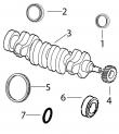
约翰迪尔(John Deere) 强鹿3029 2.9D发动机连杆瓦(标准
|
|
TRE27352
|
3
|
约翰迪尔(John Deere) 强鹿3029 2.9D发动机主轴瓦(标准)
|
|
TRE31617
|
6
|
约翰迪尔(John Deere) 强鹿3029 2.9D发动机气门密封 STEM LITER ENG
|
|
TRE44574
|
1
|
约翰迪尔(John Deere) 强鹿3029 2.9D发动机前油封
|
|
TRE501578
|
1
|
约翰迪尔(John Deere) 强鹿3029 2.9D发动机大修包
|
|
TRE66968
|
3
|
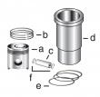
约翰迪尔(John Deere) 强鹿3029 2.9D发动机活塞缸套四配套,包括活塞,活塞环,活塞销,缸套,卡簧,阻水圈
|
|
型号
|
数量
|
描述
|
|
TAR67942
|
1
|
约翰迪尔(John Deere) 强鹿3029 2.9D发动机后油封
|
|
TAT21139
|
1
|
约翰迪尔(John Deere) 强鹿3029 2.9D发动机止推瓦(标准)
|
|
TMX504
|
1
|
约翰迪尔(John Deere) 强鹿3029 2.9D发动机试剂盒 (4)
|
|
TR504300
|
3
|
约翰迪尔(John Deere) 强鹿3029 2.9D发动机连杆衬套 PT 32 mm
|
|
TR80033
|
6
|
约翰迪尔(John Deere) 强鹿3029 2.9D发动机连杆螺钉
|
|
TRE27348
|
3
|
约翰迪尔(John Deere) 强鹿3029 2.9D发动机连杆瓦(标准
|
|
TRE27352
|
3
|
约翰迪尔(John Deere) 强鹿3029 2.9D发动机主轴瓦(标准)
|
|
TRE31617
|
6
|
约翰迪尔(John Deere) 强鹿3029 2.9D发动机气门密封 STEM LITER ENG
|
|
TRE44574
|
1
|
约翰迪尔(John Deere) 强鹿3029 2.9D发动机前油封
|
|
TRE501578
|
1
|
约翰迪尔(John Deere) 强鹿3029 2.9D发动机大修包
|
|
TRE66968
|
3
|
约翰迪尔(John Deere) 强鹿3029 2.9D发动机活塞缸套四配套,包括活塞,活塞环,活塞销,缸套,卡簧,阻水圈
|
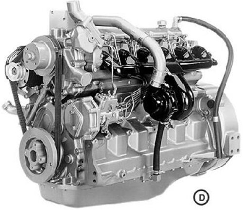
约翰迪尔(John Deere) 强鹿3029 2.9D发动机TOK2.9D9A
|
型号
|
数量
|
描述
|
|
TAR67942
|
1
|
约翰迪尔(John Deere) 强鹿3029 2.9D发动机后油封
|
|
TAT21139
|
1
|
约翰迪尔(John Deere) 强鹿3029 2.9D发动机止推瓦(标准)
|
|
TMX504
|
1
|
约翰迪尔(John Deere) 强鹿3029 2.9D发动机试剂盒 (4)
|
|
TR501124
|
6
|
约翰迪尔(John Deere) 强鹿3029 2.9D发动机连杆螺钉
|
|
TR504300
|
3
|
约翰迪尔(John Deere) 强鹿3029 2.9D发动机连杆衬套 PT 32 mm
|
|
TRE27348
|
3
|
约翰迪尔(John Deere) 强鹿3029 2.9D发动机连杆瓦(标准
|
|
TRE27352
|
3
|
约翰迪尔(John Deere) 强鹿3029 2.9D发动机主轴瓦(标准)
|
|
TRE31617
|
6
|
约翰迪尔(John Deere) 强鹿3029 2.9D发动机气门密封 STEM LITER ENG
|
|
TRE44574
|
1
|
约翰迪尔(John Deere) 强鹿3029 2.9D发动机前油封
|
|
TRE501578
|
1
|
约翰迪尔(John Deere) 强鹿3029 2.9D发动机大修包
|
|
TRE66968
|
3
|
约翰迪尔(John Deere) 强鹿3029 2.9D发动机活塞缸套四配套,包括活塞,活塞环,活塞销,缸套,卡簧,阻水圈(RE61467)
|
约翰迪尔(John Deere) 强鹿3029 2.9D发动机内部修理套件TIK2.9D9
|
型号
|
数量
|
描述
|
|
TAT21139
|
1
|
约翰迪尔(John Deere) 强鹿3029 2.9D发动机止推瓦(标准)
|
|
TR80033
|
6
|
约翰迪尔(John Deere) 强鹿3029 2.9D发动机连杆螺钉
|
|
TR97341
|
1
|
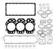
约翰迪尔(John Deere) 强鹿3029 2.9D发动机GASKET, OIL PAN 3 CYL
|
|
TRE27348
|
3
|
约翰迪尔(John Deere) 强鹿3029 2.9D发动机连杆瓦(标准
|
|
TRE27352
|
3
|
约翰迪尔(John Deere) 强鹿3029 2.9D发动机主轴瓦(标准)
|
|
TRE31617
|
6
|
约翰迪尔(John Deere) 强鹿3029 2.9D发动机气门密封 STEM LITER ENG
|
|
TRE38850
|
1
|
约翰迪尔(John Deere) 强鹿3029 2.9D发动机GASKET, CYL HEAD SET
|
|
TRE66968
|
3
|
约翰迪尔(John Deere) 强鹿3029 2.9D发动机活塞缸套四配套,包括活塞,活塞环,活塞销,缸套,卡簧,阻水圈(RE61467)
|
约翰迪尔(John Deere) 强鹿3029 2.9D发动机TIK2.9D9A
|
型号
|
数量
|
描述
|
|
TAT21139
|
1
|
约翰迪尔(John Deere) 强鹿3029 2.9D发动机止推瓦(标准)
|
|
TR501124
|
6
|
约翰迪尔(John Deere) 强鹿3029 2.9D发动机连杆螺钉
|
|
TR97341
|
1
|
约翰迪尔(John Deere) 强鹿3029 2.9D发动机GASKET, OIL PAN 3 CYL
|
|
TRE27348
|
3
|
约翰迪尔(John Deere) 强鹿3029 2.9D发动机连杆瓦(标准
|
|
TRE27352
|
3
|
约翰迪尔(John Deere) 强鹿3029 2.9D发动机主轴瓦(标准)
|
|
TRE31617
|
6
|
约翰迪尔(John Deere) 强鹿3029 2.9D发动机气门密封 STEM LITER ENG
|
|
TRE38850
|
1
|
约翰迪尔(John Deere) 强鹿3029 2.9D发动机GASKET, CYL HEAD SET
|
|
TRE66968
|
3
|
约翰迪尔(John Deere) 强鹿3029 2.9D发动机活塞缸套四配套,包括活塞,活塞环,活塞销,缸套,卡簧,阻水圈(RE61467)
|