农业
6430
6534
7130
配件详情
|
|
|
|
型号 |
数量 |
描述 |
|
TMX504 |
1 |
约翰迪尔(John Deere) 强鹿4045D 4.5D发动机试剂盒 (4) |
|
TR114083 |
8 |
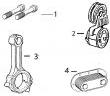
约翰迪尔(John Deere) 强鹿4045D 4.5D发动机连杆螺钉 |
|
TR115299 |
6 |
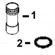
约翰迪尔(John Deere) 强鹿4045D 4.5D发动机BUSHING, BAL SHAFT |
|
TR119874 |
1 |
约翰迪尔(John Deere) 强鹿4045D 4.5D发动机轮轴衬套 |
|
TR123960 |
4 |
约翰迪尔(John Deere) 强鹿4045D 4.5D发动机连杆衬套 PT 35 mm |
|
TRE31617 |
8 |
约翰迪尔(John Deere) 强鹿4045D 4.5D发动机气门密封 STEM LITER ENG |
|
TRE44574 |
1 |
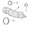
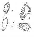
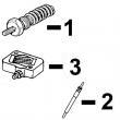
约翰迪尔(John Deere) 强鹿4045D 4.5D发动机前油封 |
|
TRE501455 |
1 |
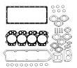
约翰迪尔(John Deere) 强鹿4045D 4.5D发动机大修包 |
|
TRE505515 |
1 |
约翰迪尔(John Deere) 强鹿4045D 4.5D发动机后油封 |
|
TRE65165 |
4 |
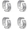
约翰迪尔(John Deere) 强鹿4045D 4.5D发动机主轴瓦(标准) |
|
TRE65168 |
1 |
约翰迪尔(John Deere) 强鹿4045D 4.5D发动机止推瓦(标准) |
|
TRE65908 |
4 |
约翰迪尔(John Deere) 强鹿4045D 4.5D发动机连杆瓦(标准 |
|
TRE65966 |
4 |
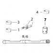
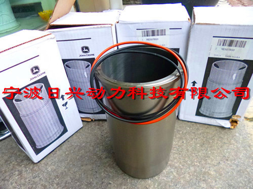
约翰迪尔(John Deere) 强鹿4045D 4.5D发动机活塞缸套四配套,包括活塞,活塞环,活塞销,缸套,卡簧,阻水圈 (RE59279) |
|
|
||||||||||||||||||||||||||||
(1)1件组合式密封和穿套; 替换TRE59810,RE538097。
(2)在曲轴加工过程中必须保持正确的轴承轴颈半径,以确保正确操作。
(3)锥形鼻子。
(4)直鼻。
(5)检查应用程序是否正确使用。
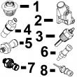
(6)线路连接都是线程化的。
(7)线路连接是一个软管倒钩& 一个线程。
(8)线路连接是两个软管倒钩。
(9)机器分体式和断裂式分体式连杆均可用于同一台发动机,但每个连杆必须使用正确的连杆螺栓。
强鹿JOHN DEERE柴油机配件、发动机配件、发电机组:
RE515368、RE62420、RE65414(24V)、RE500227、SE501836、SE501828、SE501823、RE533516、RE525690、RE16809、RE16808、RE509672、RE525523、RE523236、RE525523、RE62424、RE504564、RE160384、RE557343、RE533910、RE532952、RE530107、RE531808、RE507981、RE532627、RE518176、RE532628、RE519774、RE533608、RE522528、RE519774、RE532628、 RE518176、RE507980、RE518503、RE522515、RE504836、RE509031、RE509032
pn=227 1j21 oil filter 8806 cd41052 -un-05dec96 0 0 4 6 5 8 t t engine & & key part no- part name qty serial no- h h remarks 1 - fitting na x x m16 x 1-5 2 - o-ring na x x 3 re59906 filter head 1 x x (marked r134570) 4 r123591 threaded nipple 1 x x 5 re59754 oil filter 1 x x 6 19m7835 screw 2 x x m10 x 35, (10-9) 7 r114358 spacer 1 x x 12 x 25-400 x 12-700 mm 8 re46687 fitting 2 x x m22 x 1-5 9 51m7045 o-ring 1 x x 19-300 x 2-200 mm 8800-8806 engines for gensets 4039/4-5l/6-8l (007/157) pc2465 (26-feb-99) pn=228 1j22 oil filter 8806 - continued cd41053 -un-05dec96 0 0 4 6 5 8 t t engine & & key part no- part name qty serial no- h h remarks 1 19m7802 screw 3 x x m8 x 65, (10-9) 2 re67238 screw 1 x x threads sealant coated 3 19m7913 screw 2 x x m8 x 90, (10-9) 4 r135916 adapter 1 x x 5 r72328 o-ring 4 x x 6 r135270 tube 1 x x 7 r135271 tube 1 x x 8 r123504 gasket 1 x x engines for gensets 4039/4-5l/6-8l (007/157) pc2465 (26-feb-99) 8800-8806a pn=229 oil filter memoranda 8800-8806b engines for gensets 4039/4-5l/6-8l (007/157) pc2465 (26-feb-99) pn=230 1k3 engine base (039) sectional index cd42773 -un-22feb99 9701 - 1k5 9702 - 1k6 9703 - 1k7 9704 - 1k8 9705 - 1k9 9706 - 1k10 9708 - 1k12 9709 - 1k13 9710 - 1k14 9711 - 1k15 9712 - 1k16 9713 - 1k17 9714 - 1k18 9715 - 1k19 9716 - 1k20 9717 - 1k21 9718 - 1k22 9720 - 1k24 9721 - 1k25 9722 - 1l1 9723 - 1l2 9724 - 1l3 9725 - 1l4 9726 - 1l5 9727 - 1l6 9728 - 1l7 9729 - 1l8 engines for gensets 4039/4-5l/6-8l (007/157) pc2465 (26-feb-99) 9700-a01 pn=231 1k4 engine base (039) sectional index cd42774 -un-24feb99 9701 - 1k5 9702 - 1k6 9703 - 1k7 9704 - 1k8 9705 - 1k9 9706 - 1k10 9708 - 1k12 9709 - 1k13 9710 - 1k14 9711 - 1k15 9712 - 1k16 9713 - 1k17 9714 - 1k18 9715 - 1k19 9716 - 1k20 9717 - 1k21 9718 - 1k22 9720 - 1k24 9721 - 1k25 9722 - 1l1 9723 - 1l2 9724 - 1l3 9725 - 1l4 9726 - 1l5 9727 - 1l6 9728 - 1l7 9729 - 1l8 9700-a02 engines for gensets 4039/4-5l/6-8l (007/157) pc2465 (26-feb-99) pn=232 1k5 engine base (039) 9701 cd37239a -un-01jan94 0 3 9 d engine & key part no- part name qty serial no- t remarks 1 r54565 plug 2 x 2 dd12120 rocker arm shaft 1 x 3 t20316 washer 2 x 4 t20314 spring 2 x 5 19h3031 cap screw 3 x 3/8" x 2-1/2", (sae 8) 6 r42729 washer 3 x 7 t20315 support 3 x 8 re31973 rocker arm 6 x 9 t20310 push rod 6 x lgth 234mm 10 t20073 tappet 6 x engines for gensets 4039/4-5l/6-8l (007/157) pc2465 (26-feb-99) 9700-9701 pn=233 1k6 engine base (039) 9702 cd37203a -un-02sep98 0 0 3 3 engine 9 9 key part no- part name qty serial no- d t remarks 1 r85363 cap screw 18 x x 12-7mm x 112mm 2 - cylinder head 1 x marked r116569, ord re48615,t58477, ty9371/t43513, appl re48615 cylinder head 1 x x (marked r111949) with valves, also order t58477,ty9374/ty9375, appl 3 cd16284 cap ar x x od 32-6mm a3910r cap ar x x od 25-4mm (1") 4 r43409 cap ar x x od 43-3mm 5 - valve seat insert ar x x ord r106831 + r106829 6 r104592 pipe plug ar x x 1/8"-27npt , 7 r92425 engine cylinder head gasket 1 x x 8 t58477 pipe plug ar x 7/8"-14unf, (also order ty9371/t43513) appl t58477 pipe plug ar x 7/8"-14unf, (also order ty9374/ty9375) appl 9 ty9371 adhesive ar x loctite 271, 6ml (0-2 oz) t43513 adhesive ar x loctite 271, 50ml (1-7 oz) ty9374 sealant ar x loctite 572/592, 6ml (0-2 oz) ty9375 sealant ar x loctite 572/592, 50ml (1-7 oz) 9700-9702 engines for gensets 4039/4-5l/6-8l (007/157) pc2465 (26-feb-99) pn=234 1k7 engine base (039) 9703 cd37204 -un-01jan94 0 3 9 d engine & key part no- part name qty serial no- t remarks 1 r91889 retainer 16 x od 11-7mm 2 re60005 rotator 8 x 3 r26125 spring 8 x 4 re31617 seal 8 x id standard, 5 r106831 valve seat insert 4 x od 47-22mm, intake 6 r98062 intake valve 4 x od standard r97490 intake valve ar x od +0-381mm r97491 intake valve ar x od +0-762mm 7 r106829 valve seat insert 4 x od 43-1mm, exhaust 8 r90692 exhaust valve 4 x od standard r97492 exhaust valve ar x od +0-381mm r97493 exhaust valve ar x od +0-762mm engines for gensets 4039/4-5l/6-8l (007/157) pc2465 (26-feb-99) 9700-9703 pn=235 1k8 engine base (039) 9704 cd42120 -un-30jul98 0 3 9 d engine & key part no- part name qty serial no- t remarks 1 at21140 bearing 4 x (kit (2) t23214) std - bearing ar x (a) us -0-254mm, marked t23554, ord re27353 2 at21139 bearing 1 x (kit (2) t23215) std, rear - bearing ar x (a) us -0-254mm, rear,marked t23576, ord re27351&re13571 (a) grinding guideline : ctm3274 9700-9704 engines for gensets 4039/4-5l/6-8l (007/157) pc2465 (26-feb-99) pn=236 1k9 engine base (039) 9705 cd40310a -un-22jan97 0 3 9 d engine & key part no- part name qty serial no- t remarks 1 re55901 kit 1 x (also order ty6333) incl instructions 2 26h72 shaft key 1 x 1/8" x 5/8" 3 - camshaft 1 x a = 40mm, marked r115335, ord re55901 4 t20073 tappet 8 x 5 r119874 bushing ar x 6 19h2676 cap screw 2 x 3/8" x 1", (sae 8) 7 t20070 helical gear 1 x z = 48 8 t20072 plate 1 x engines for gensets 4039/4-5l/6-8l (007/157) pc2465 (26-feb-99) 9700-9705 pn=237 1k10 engine base (039) 9706 cd37255a -un-16jan97 this parts listing is continued 9700-9706 engines for gensets 4039/4-5l/6-8l (007/157) pc2465 (26-feb-99) pn=238 1k11 engine base (039) 0 3 9 d engine & key part no- part name qty serial no- t remarks 1 re51870 kit 1 x w/ instructions 2 19h2676 cap screw 2 x 3/8" x 1", (sae 8) 3 t20072 plate 1 x 4 26h72 shaft key 1 x 1/8" x 5/8" 5 - camshaft 1 x marked r115335, ord kit re55901 6 t20073 tappet 8 x 7 r54802 orifice 4 x 8 a120r dowel pin 4 x 9 b153r dowel pin 2 x low 10 19h1726 cap screw 2 x 3/8" x 2-1/4" 11 r130883 stud 1 x lgth 47mm, 3/8"-16nc x 3/8"-16unc 12 t18891 cap 1 x 13 r26493 bushing 1 x 14 - spring 1 x lgth 51mm, nsep, order kit re63674 15 - valve 1 x lgth 41mm, nsep, order kit re63674 16 t23474 cap screw 10 x 17 r32214 washer 10 x 18 r65215 bearing cap 4 x 19 r79089 cap 1 x rear 20 r97185 o-ring 1 x 21 - cylinder block 1 x marked r116194, nsep, order kit re51870 22 15h623 pipe plug 1 x 3/8"-18npt 23 15h690 pipe plug 1 x 3/4"-14nptf use with 15h690 24 15h616 pipe bushing 1 x 1"-11-5nptf x 3/4"-14nptf use with 15h665 25 r104592 pipe plug 5 x 1/8"-27npt, with sealant 26 re502422 drain plug 1 x 27 r501377 o-ring 1 x 28 r55233 pipe plug 1 x 1/4"-18npt 29 r119874 bushing 1 x (also order ty6333) 30 15h584 pipe plug 2 x 1/2"-14npt 31 t23435 threaded nipple 1 x 32 15h562 pipe plug 1 x 1"-11-5nptf 33 r119210 bushing 6 x od std r91708 bushing ar x os +2mm 34 19h2351 cap screw 1 x 1/2" x 1/2" 35 t24608 washer 1 x 36 r121194 adapter 1 x 1/2"-13unc x 1/2"-14nptf 37 14h1076 nut 1 x 3/8"-16unc, hs sae 8 38 r75892 o-ring 1 x (use with r75893) 39 r75893 fitting 1 x (use with r75892) 40 re63674 kit 1 x 41 at13740 drain valve ar x engines for gensets 4039/4-5l/6-8l (007/157) pc2465 (26-feb-99) 9700-9707 pn=239 1k12 engine base (039) 9708 cd40213 -un-23may95 0 0 3 3 engine 9 9 key part no- part name qty serial no- d t remarks 1 re24458 piston-liner kit 4 x re22678 piston-liner kit 4 x 2 re66820 piston ring kit 1 x x packg (3) 3 - piston 1 x marked re19282, ord re24458 - piston 1 x marked re48368, ord re22678 4 r131575 cylinder liner 1 x x a = 196mm 5 ar65507 o-ring kit 1 x x packg (3) 6 cd15466 shim ar x x tk 0-05mm r65833 shim ar x x tk 0-10mm 9700-9708 engines for gensets 4039/4-5l/6-8l (007/157) pc2465 (26-feb-99) pn=240 1k13 engine base (039) 9709 cd40214 -un-23may95 0 0 3 3 engine 9 9 key part no- part name qty serial no- d t remarks 1 re21076 connecting rod 4 x (marked r80034) re42733 connecting rod 4 x (marked r80034) 2 r80033 screw 2 x x 3 re63914 piston pin 4 x kit re63913 piston pin 4 x kit 4 m41029 snap ring 2 x packg (6) r54114 snap ring 2 x packg (6) 5 - piston pin 1 x od 35mm, ord re63914 - piston pin 1 x od 41mm, ord re63913 6 - bushing 1 x ord re63914 - bushing 1 x ord re63913 7 - bearing 4 x marked t20011, std,order re27348 re27348 bearing 4 x (kit (2) r83379) std re27349 bearing ar x x (a) (kit (2) r87748) us -0-254mm (a) grinding guideline : ctm3274 engines for gensets 4039/4-5l/6-8l (007/157) pc2465 (26-feb-99) 9700-9709 pn=241 1k14 engine base (039) 9710 cd40036 -un-26mar96 0 3 9 d engine & key part no- part name qty serial no- t remarks 1 re65224 crankshaft 1 x kit 2 ar67942 seal 1 x front 3 t20046 oil slinger 1 x 4 - spur gear na x z = 24 5 t20094 helical gear 1 x z = 24 6 - crankshaft 1 x (a) a = 60mm, marked r121018, ord re65224 7 26h72 shaft key 1 x 1/8" x 5/8" 8 re27352 bearing 4 x id std, (kit (2) t23214) 9 re27348 bearing 4 x id std, (kit (2) r83379) 10 re60350 bearing 1 x id std, (kit (2) r121413) 11 re13571 thrust washer 1 x tk std, (kit (4) r78598) 12 re44574 seal 1 x rear 13 a120r dowel pin 1 x 14 r81989 sleeve 1 x 15 h35244 o-ring 1 x (a) grinding guidelines : see ctm8/ctm3274 9700-9710 engines for gensets 4039/4-5l/6-8l (007/157) pc2465 (26-feb-99) pn=242 1k15 engine base (039) 9711 cd42121 -un-13mar98 0 3 9 d engine & key part no- part name qty serial no- t remarks 1 dd15070 crankshaft ar x kit , w/o key 3, (also order r100850) 2 ar67942 seal 1 x front 3 t20046 oil slinger ar x 4 - helical gear na x z = 24 5 - crankshaft 1 x a = 60mm, marked "r", ord dd15070 6 26h72 shaft key 1 x 1/8" x 5/8" 7 r48685 dowel pin 1 x 8 re27353 bearing 4 x id -0-254mm, (kit (2) r87750) 9 re27351 bearing 1 x id -0-254mm, (kit (2) r87749) 10 re13571 thrust washer 1 x tk = standard, (kit (4) r78598) 11 re27349 bearing 4 x id -0-254mm, (kit (2) r87748) connecting rod 12 re44574 seal 1 x rear engines for gensets 4039/4-5l/6-8l (007/157) pc2465 (26-feb-99) 9700-9711 pn=243 1k16 engine base (039) 9712 cd37327a -un-20jul95 0 3 9 d engine & key part no- part name qty serial no- t remarks 1 re51527 kit ar x incl- instructions 2 19h3065 cap screw 5 x 3/8" x 2", (sae 8) 3 24m7106 washer 16 x 10 x 18 x 2-500 mm 4 19h2733 cap screw 4 x 3/8" x 2-3/8", (sae 8) 5 19h3031 cap screw 2 x 3/8" x 2-1/2", (sae 8) 6 19h2549 cap screw 2 x 3/8" x 1-7/8" 7 19h1726 cap screw 2 x 3/8" x 2-1/4" 8 19h2284 cap screw 1 x 3/8" x 7/8" 9 ar67942 seal 1 x 10 re52977 drain plug 1 x m42 x 2 11 51m7049 o-ring 1 x 38-600 x 2-900 mm 12 t23260 cover 1 x 13 r97352 gasket 1 x 14 r91692 plug 1 x 15 a4827r washer 1 x 16 - cover 1 x aluminium, marked r114217, ord re51527 17 r97454 gasket 1 x 18 51m7044 o-ring 2 x 17-300 x 2-200 mm 19 re38028 sen*** 1 x 20 r65607 terminal 1 x 21 ty16086 ground cable 1 x lgth 30-5m, cut to length 22 r77491 terminal 1 x 9700-9712 engines for gensets 4039/4-5l/6-8l (007/157) pc2465 (26-feb-99) pn=244 1k17 engine base (039) 9713 cd35803a -un-01jan94 0 3 9 d engine & key part no- part name qty serial no- t remarks 1 r131794 gasket 1 x 2 12h324 washer 5 x 3/8" 3 t20166 screw 5 x 4 r79863 plate 1 x (also order (8) at21191&(2) at22919) 5 r79854 washer ar x od x id 50mm x 46mm 6 at21191 set screw 8 x 5/16" x 0-380" 7 at22919 set screw 2 x 3/8" x 0-380" 8 t23442 stud 3 x lgth 36-6mm x 5/16"-24ns x 5/16"-18unc 9 a22698 nut 3 x 5/16"-18unc engines for gensets 4039/4-5l/6-8l (007/157) pc2465 (26-feb-99) 9700-9713 pn=245 1k18 engine base (039) 9714 cd39157 -un-01jan94 0 3 9 d engine & key part no- part name qty serial no- t remarks 1 t26327 screw 1 x 2 r101227 thrust washer 1 x 14-7 x 57-9 x 4mm, front 3 ar91660 helical gear 1 x (marked r70182) z = 55 4 t20034 bushing 1 x 5 r109863 pin 1 x od 44-5mm 6 r101225 thrust washer 1 x 22 x 60 x 3mm, rear 9700-9714 engines for gensets 4039/4-5l/6-8l (007/157) pc2465 (26-feb-99) pn=246 1k19 engine base (039) 9715 cd39158 -un-01jan94 0 3 9 d engine & key part no- part name qty serial no- t remarks 1 14h865 nut 1 x 1/2"-20unf 2 r101227 thrust washer 1 x 14-7 x 57-9 x 4mm, front 3 at24252 helical gear 1 x (marked t26322) z = 45 4 t26321 bushing 1 x 5 r109863 pin 1 x od 44-5mm 6 r101225 thrust washer 1 x 22mm x 60mm, rear 7 r100105 washer 1 x 13-5 x 30 x 3mm, rear 8 19h3011 cap screw 1 x 1/2" x 2-1/8", (sae 8) engines for gensets 4039/4-5l/6-8l (007/157) pc2465 (26-feb-99) 9700-9715 pn=247 1k20 engine base (039) 9716 cd42124 -un-17mar98 0 3 9 d engine & key part no- part name qty serial no- t remarks 1 re52020 kit 1 x 2 14h826 nut 1 x 1/2"-13unc 3 r61871 o-ring 1 x 4 r74354 o-ring 1 x 5 r97185 o-ring ar x 6 r113752 oil tube na x w/ color mark 7 r115280 oil tube 1 x appl 8 r75892 o-ring ar x 9 - spur gear na x z = 33 10 t20298 helical gear 1 x z = 33 11 r57059 cap screw 1 x lgth 70mm 12 12h304 lock washer 1 x 3/8" 9700-9716 engines for gensets 4039/4-5l/6-8l (007/157) pc2465 (26-feb-99) pn=248 1k21 engine base (039) 9717 cd41102a -un-16sep98 0 3 9 d engine & key part no- part name qty serial no- t remarks 1 re62658 kit ar x with installation instructions 2 r97455 gasket 1 x 3 t20243 gasket 1 x 4 - impeller 1 x cast iron, marked t30897, ord re62658 5 r134742 tool 1 x engines for gensets 4039/4-5l/6-8l (007/157) pc2465 (26-feb-99) 9700-9717 pn=249 1k22 engine base (039) 9718 cd10410 -un-01jan94 this parts listing is continued 9700-9718 engines for gensets 4039/4-5l/6-8l (007/157) pc2465 (26-feb-99) pn=250 1k23 engine base (039) 0 3 9 d engine & key part no- part name qty serial no- t remarks 1 re64290 gasket kit 1 x (a) 2 ar65507 o-ring kit 4 x packg (3) 3 re64291 gasket kit 1 x (b) incl key 2 (a) tune-up (b) overhaul engines for gensets 4039/4-5l/6-8l (007/157) pc2465 (26-feb-99) 9700-9719 pn=251 1k24 engine base (039) 9720 cd35696 -un-01jan94 0 3 9 d engine & key part no- part name qty serial no- t remarks 1 dd15664 liquid gasket ar x kit 9700-9720 engines for gensets 4039/4-5l/6-8l (007/157) pc2465 (26-feb-99) pn=252 1k25 engine base (039) 9721 cd39055 -un-01jan94 0 3 9 d engine & key part no- part name qty serial no- t remarks 1 ty6333 grease ar x 397 g (14 oz) engines for gensets 4039/4-5l/6-8l (007/157) pc2465 (26-feb-99) 9700-9721 pn=253 1l1 engine base (039) 9722 tp6956 -un-01jan94 0 3 9 d engine & key part no- part name qty serial no- t remarks 1 eph76215-005 cool-gard ar x 5l eph76215-025 cool-gard ar x 25l eph76215-050 cool-gard ar x 50l eph76215-200 cool-gard ar x 200l 9700-9722 engines for gensets 4039/4-5l/6-8l (007/157) pc2465 (26-feb-99) pn=254 1l2 engine base (039) 9723 cd37321a -un-20jul95 0 3 9 d engine & key part no- part name qty serial no- t remarks 1 19h1732 cap screw 2 x 3/8" x 1-1/4" 2 24m7106 washer 2 x 10 x 18 x 2-500 mm 3 - fuel filter 1 x 4 r119988 bracket 1 x 5 n10215 lock nut 2 x 3/8" 6 19h2284 cap screw 2 x 3/8" x 7/8" 7 12h304 lock washer 2 x 3/8" 8 at32333 elbow fitting 2 x 1/2"-20unf x 1/2"-20unf 9 r26286 o-ring 2 x 10 re62158 pipe plug 2 x 1/2"-20unf 11 re56667 fuel line 1 x 12 19h2021 cap screw 1 x 3/8" x 5/8" 13 r120966 bracket 1 x 14 19h2664 cap screw 1 x 5/16" x 3/4", (sae 8) 15 t13914 clamp 1 x 16 a22698 nut 1 x 5/16" engines for gensets 4039/4-5l/6-8l (007/157) pc2465 (26-feb-99) 9700-9723 pn=255 1l3 engine base (039) 9724 cd42413a -un-18nov98 0 3 9 d engine & key part no- part name qty serial no- t remarks 1 - kit 1 x (also order (2) r26286&(2) re62158) 2 - filter head 1 x 3 - drain plug 1 x ord re60854 4 r113565 packing 1 x 5 - retainer 1 x ord re51649 6 - o-ring 1 x ord re50752 7 r26286 o-ring 2 x 8 re62158 pipe plug 2 x 1/2"-20unf 9700-9724 engines for gensets 4039/4-5l/6-8l (007/157) pc2465 (26-feb-99) pn=256 1l4 engine base (039) 9725 cd42420 -un-03mar98 0 3 9 d engine & key part no- part name qty serial no- t remarks 1 re60021 fuel filter 1 x a = 71mm, (also order r113565) 2 r113565 packing 1 x 3 re60854 kit 1 x engines for gensets 4039/4-5l/6-8l (007/157) pc2465 (26-feb-99) 9700-9725 pn=257 1l5 engine base (039) 9726 cd42421 -un-03mar98 0 3 9 d engine & key part no- part name qty serial no- t remarks 1 re51649 kit ar x incl- instructions 2 re50752 seal kit ar x 9700-9726 engines for gensets 4039/4-5l/6-8l (007/157) pc2465 (26-feb-99) pn=258 1l6 engine base (039) 9727 cd39026 -un-01jan94 0 3 9 d engine & key part no- part name qty serial no- t remarks 1 re50467 hand primer 1 x (a) (a) acces***y engines for gensets 4039/4-5l/6-8l (007/157) pc2465 (26-feb-99) 9700-9727 pn=259 1l7 engine base (039) 9728 cd39137a -un-01jan94 0 3 9 d engine & key part no- part name qty serial no- t remarks 1 re51648 kit ar x (a) incl- instructions 2 - wing nut 1 x ord kit re51649 3 - heater 1 x (12v - 150w) ord kit re51648 4 - o-ring 1 x ord kit re50752 (a) acces***y 9700-9728 engines for gensets 4039/4-5l/6-8l (007/157) pc2465 (26-feb-99) pn=260 1l8 engine base (039) 9729 cd39136b -un-15feb96 0 3 9 d engine & key part no- part name qty serial no- t remarks 1 re51650 sediment bowl ar x (a) kit, incl- instructions 2 - o-ring 1 x ord kit re50752 3 - wing nut 1 x ord kit re51650 4 - o-ring 1 x ord kit re50752 5 - sediment bowl 1 x ord kit re51650 6 - o-ring 1 x ord kit re50752 7 - screw 1 x ord kit re51650 8 - gasket 1 x ord kit re60854 9 - o-ring 1 x ord kit re60854 10 - drain plug 1 x ord kit re60854 (a) acces***y engines for gensets 4039/4-5l/6-8l (007/157) pc2465 (26-feb-99) 9700-9729 pn=261 engine base (039) memoranda 9700-9730 engines for gensets 4039/4-5l/6-8l (007/157) pc2465 (26-feb-99) pn=262 2b3 engine base (045) sectional index cd42775 -un-24feb99 9801 - 2b5 9802 - 2b6 9803 - 2b7 9804 - 2b8 9806 - 2b10 9808 - 2b12 9809 - 2b13 9810 - 2b14 9811 - 2b15 9812 - 2b16 9813 - 2b17 9814 - 2b18 9815 - 2b19 9816 - 2b20 9818 - 2b21 9820 - 2b23 9821 - 2b24 9822 - 2b25 9823 - 2c1 9824 - 2c2 9825 - 2c3 9826 - 2c4 9827 - 2c5 9828 - 2c6 9829 - 2c7 9830 - 2c8 engines for gensets 4039/4-5l/6-8l (007/157) pc2465 (26-feb-99) 9800-a01 pn=263 2b4 engine base (045) sectional index cd42776 -un-24feb99 9801 - 2b5 9802 - 2b6 9803 - 2b7 9804 - 2b8 9806 - 2b10 9808 - 2b12 9809 - 2b13 9810 - 2b14 9811 - 2b15 9812 - 2b16 9813 - 2b17 9814 - 2b18 9815 - 2b19 9816 - 2b20 9818 - 2b21 9820 - 2b23 9821 - 2b24 9822 - 2b25 9823 - 2c1 9824 - 2c2 9825 - 2c3 9826 - 2c4 9827 - 2c5 9828 - 2c6 9829 - 2c7 9830 - 2c8 9800-a02 engines for gensets 4039/4-5l/6-8l (007/157) pc2465 (26-feb-99) pn=264 2b5 engine base (045) 9801 cd41045 -un-12jun96 0 4 5 t engine & key part no- part name qty serial no- h remarks 1 r54565 plug 2 x 2 r123513 rocker arm shaft 1 x 3 t20316 washer 2 x 4 t20314 spring 3 x 5 r123271 stud 4 x 6 r42729 washer 4 x 7 r123161 support 4 x 8 14m7148 nut 1 x m10 9 re68695 rocker arm 8 x 10 r107731 push rod 8 x 11 r123565 cam follower 8 x engines for gensets 4039/4-5l/6-8l (007/157) pc2465 (26-feb-99) 9800-9801 pn=265 2b6 engine base (045) 9802 cd41004a -un-10jun98 0 4 5 t engine & key part no- part name qty serial no- h remarks 1 r85363 cap screw 18 x 12-7mm x 112mm 2 re57234 cylinder head 1 x (marked r121402) assy, incl keys 3,4,5- high swirl 3 cd16284 cap 1 x od 32-6mm, rear cd16607 cap ar x od 34-3mm, rear r43409 cap 3 x od 43-3mm 4 r104592 pipe plug ar x 1/8"-27npt 5 t58477 fitting 1 x 7/8"-14unf, (also order ty9374/ty9375) appl 6 ty9374 sealant ar x loctite 592, 6ml (0-2 oz) ty9375 sealant ar x loctite 592, 50ml (1-7 oz) 7 r116515 engine cylinder head gasket 1 x 9800-9802 engines for gensets 4039/4-5l/6-8l (007/157) pc2465 (26-feb-99) pn=266 2b7 engine base (045) 9803 cd37204 -un-01jan94 0 4 5 t engine & key part no- part name qty serial no- h remarks 1 r91889 retainer 16 x 2 re60005 rotator 8 x 3 r26125 spring 8 x 4 re31617 seal 8 x std 5 r106831 valve seat insert 4 x 6 r98062 intake valve 4 x std r97490 intake valve ar x od +0-381mm r97491 intake valve ar x od +0-762mm 7 r106829 valve seat insert 4 x 8 r90692 exhaust valve 4 x std r97492 exhaust valve ar x od +0-381mm r97493 exhaust valve ar x od +0-762mm engines for gensets 4039/4-5l/6-8l (007/157) pc2465 (26-feb-99) 9800-9803 pn=267 2b8 engine base (045) 9804 cd41801a -un-08dec98 this parts listing is continued 9800-9804 engines for gensets 4039/4-5l/6-8l (007/157) pc2465 (26-feb-99) pn=268 2b9 engine base (045) 0 4 5 t engine & key part no- part name qty serial no- h remarks 1 - cylinder block 1 x marked r115081, ord re65957 + re501455 + re502269 + dd15664 2 a120r dowel pin 4 x 3 r131182 orifice 4 x 4 re502422 drain plug 2 x 1-5/8"-12un 5 r501377 o-ring 2 x 6 r116466 plug 1 x 7 r119874 bushing 1 x (also order ty6333) 8 t18891 cap 2 x od 16mm 9 b153r dowel pin 2 x 9-525 x 25-400mm 10 r26493 bushing 1 x 11 r115299 bushing 6 x 12 r115390 bushing ar x for r75892 13 r75892 o-ring ar x for r115390 14 r97185 o-ring 1 x 15 re63674 valve 1 x kit 16 15h623 pipe plug 1 x 3/8"-18npt 17 r114241 bearing cap 4 x 18 t20168 washer 10 x 19 t23474 cap screw 10 x 20 r132186 bearing cap 1 x rear 21 15h584 pipe plug ar x 1/2"-14npt 22 r104592 pipe plug 5 x 1/8"-27npt 23 r55233 pipe plug 1 x 1/4"-18npt 24 at13740 drain valve ar x 25 - cap screw ar x m12 26 - cap screw ar x m12 engines for gensets 4039/4-5l/6-8l (007/157) pc2465 (26-feb-99) 9800-9805 pn=269 2b10 engine base (045) 9806 cd41802a -un-23feb99 this parts listing is continued 9800-9806 engines for gensets 4039/4-5l/6-8l (007/157) pc2465 (26-feb-99) pn=270 2b11 engine base (045) 0 4 5 t engine & key part no- part name qty serial no- h remarks 1 re65957 short block assembly 1 x (also order re501455, re502269&dd15664) engines for gensets 4039/4-5l/6-8l (007/157) pc2465 (26-feb-99) 9800-9807 pn=271 2b12 engine base (045) 9808 cd41007d -un-13mar98 0 4 5 t engine & key part no- part name qty serial no- h remarks 1 19m7867 screw 2 x m8 x 25, (10-9) 2 r132518 plate 1 x 3 r133303 shaft key 1 x 4 - helical gear 1 x z= 60 , marked r133812, nsep, ord re56375 5 - camshaft 1 x nsep, ord re56375 6 re56375 camshaft 1 x 9800-9808 engines for gensets 4039/4-5l/6-8l (007/157) pc2465 (26-feb-99) pn=272 2b13 engine base (045) 9809 cd40211 -un-23may95 0 4 5 t engine & key part no- part name qty serial no- h remarks 1 re65969 piston-liner kit 4 x 2 re66820 piston ring kit 1 x packg (3) 3 - piston 1 x marked re55512, nsep, ord re65969 4 - cylinder liner 1 x a = 218mm, nsep, ord re65969 5 ar65507 o-ring kit 1 x packg (3) 6 - shim na x engines for gensets 4039/4-5l/6-8l (007/157) pc2465 (26-feb-99) 9800-9809 pn=273 2b14 engine base (045) 9810 cd41009 -un-26feb96 0 4 5 t engine & key part no- part name qty serial no- h remarks 1 re50770 connecting rod 4 x (marked r114081) 2 r114083 screw 2 x 3 r114082 bushing 1 x 4 r54114 snap ring 8 x 5 r123177 piston pin 4 x od 41mm , lgth 72mm 6 re65908 bearing 4 x (kit (2) r113698) std re65909 bearing ar x (kit (2) r130578) id -0-254mm 9800-9810 engines for gensets 4039/4-5l/6-8l (007/157) pc2465 (26-feb-99) pn=274 2b15 engine base (045) 9811 cd42779 -un-24feb99 0 4 5 t engine & key part no- part name qty serial no- h remarks 1 re59810 kit 1 x front 2 r120631 helical gear 1 x z = 30 3 re50618 crankshaft 1 x assy, incl keys 2,4,5, (marked r113596) (also order re59810&re44574) 4 26m4224 shaft key 1 x 4 x 16 mm 5 a120r dowel pin 1 x 12-725 x 28-448 mm 6 re65165 bearing kit 4 x (kit r123561&r123562) std re65911 bearing ar x (kit r130576&r130577) id -0-254 mm 7 re65168 thrust bearing 1 x (kit r123563&r123564) std re65912 thrust bearing ar x (kit r130574&r130575) id -0-254 mm engines for gensets 4039/4-5l/6-8l (007/157) pc2465 (26-feb-99) 9800-9811 pn=275 2b16 engine base (045) 9812 cd41028 -un-11mar96 0 4 5 t engine & key part no- part name qty serial no- h remarks 1 r136475 screw 4 x 2 r134527 plate 1 x 3 dd15664 liquid gasket 1 x 4 r116386 stud 3 x 5 14m7298 flange nut 3 x m8, (10) 9800-9812 engines for gensets 4039/4-5l/6-8l (007/157) pc2465 (26-feb-99) pn=276 2b17 engine base (045) 9813 cd41823 -un-09apr98 0 4 5 t engine & key part no- part name qty serial no- h remarks 1 19m7807 screw 1 x m10 x 60, (10-9) 2 r131283 thrust washer 1 x 11 x 60 x 3mm 3 re500631 helical gear 1 x z = 49, (marked r500363) assy 4 t20034 bushing 1 x 5 r109863 shaft 1 x od 44-5mm 6 r101225 thrust washer 1 x 22 x 60 x 3mm engines for gensets 4039/4-5l/6-8l (007/157) pc2465 (26-feb-99) 9800-9813 pn=277 2b18 engine base (045) 9814 cd41027c -un-10apr98 0 4 5 t engine & key part no- part name qty serial no- h remarks 1 19m8292 screw 1 x m10 x 50, (10-9) 2 r131283 thrust washer 1 x 11 x 60 x 3mm 3 re56369 helical gear 1 x z = 43, (marked r120636) 4 r114193 bushing 1 x od 47-7mm 5 r114194 shaft 1 x od 44-5mm 6 r101225 thrust washer 1 x 22 x 60 x 3mm 9800-9814 engines for gensets 4039/4-5l/6-8l (007/157) pc2465 (26-feb-99) pn=278 2b19 engine base (045) 9815 cd41805b -un-24feb99 0 4 5 t engine & key part no- part name qty serial no- h remarks 1 19m7802 screw 2 x m8 x 65, (10-9) 2 re502269 oil pump 1 x assy, incl key 5 3 r120638 helical gear 1 x z = 30 4 14m7066 nut 1 x m12 5 r97185 o-ring 1 x 6 r121376 tube 1 x 7 19m8986 screw 2 x m8 x 100, (10-9) engines for gensets 4039/4-5l/6-8l (007/157) pc2465 (26-feb-99) 9800-9815 pn=279 2b20 engine base (045) 9816 cd41050b -un-19feb98 0 4 5 t engine & key part no- part name qty serial no- h remarks 1 re71240 kit ar x (also order r123417&r123226) 2 a364r snap ring 1 x 3 - impeller 1 x marked r121036, ord re71240 4 r123226 gasket 1 x 9800-9816 engines for gensets 4039/4-5l/6-8l (007/157) pc2465 (26-feb-99) pn=280 engine base (045) memoranda engines for gensets 4039/4-5l/6-8l (007/157) pc2465 (26-feb-99) 9800-9817 pn=281 2b21 engine base (045) 9818 tp49293 -un-27sep95 this parts listing is continued 9800-9818 engines for gensets 4039/4-5l/6-8l (007/157) pc2465 (26-feb-99) pn=282 2b22 engine base (045) 0 4 5 t engine & key part no- part name qty serial no- h remarks 1 r123542 gasket 1 x 2 r109985 gasket 4 x 3 r135896 gasket 1 x 4 r123226 gasket 2 x 5 r123345 gasket 1 x 6 r123570 gasket 1 x 7 r123575 gasket 4 x 8 r116515 gasket 1 x 9 r54638 gasket 1 x 10 r81275 gasket 1 x 11 r92097 gasket 1 x 12 r123353 gasket 1 x 13 r123352 gasket 1 x appl 14 r75892 o-ring 1 x 15 r97185 o-ring 1 x 16 r61871 o-ring 1 x 17 a4827r washer 1 x 18 re44574 seal 1 x 19 re59810 seal kit 1 x 20 r123273 o-ring 1 x 21 r123417 gasket 1 x 22 r136516 gasket 1 x appl r136515 gasket 1 x 23 r123501 gasket 1 x 24 r123504 gasket 1 x appl r500374 gasket 1 x 25 r123525 gasket 1 x 26 r53108 gasket 1 x 27 r72328 o-ring 4 x 28 r89944 o-ring 1 x 29 r61105 o-ring 2 x 30 t122075 o-ring 2 x 31 r123502 gasket 1 x 32 re501455 gasket kit 1 x (also order r133893, r501459, (4) ar65507, r105346, r123583&dd15664) appl engines for gensets 4039/4-5l/6-8l (007/157) pc2465 (26-feb-99) 9800-9819 pn=283 2b23 engine base (045) 9820 cd42425 -un-11mar98 0 4 5 t engine & key part no- part name qty serial no- h remarks 1 r123542 gasket 1 x 2 r109985 gasket 4 x 3 r135896 gasket 1 x 4 r123226 gasket 2 x 5 r123345 gasket 1 x 6 r123570 gasket 1 x 7 r123575 o-ring 4 x 8 r116515 engine cylinder head gasket 1 x 9 r54638 gasket 1 x 10 r81275 gasket 1 x 11 r92097 gasket 1 x 12 re66082 gasket kit 1 x (also order r133893, r501459, r105346, r123583&dd15664) appl 9800-9820 engines for gensets 4039/4-5l/6-8l (007/157) pc2465 (26-feb-99) pn=284 2b24 engine base (045) 9821 cd35696 -un-01jan94 0 4 5 t engine & key part no- part name qty serial no- h remarks 1 dd15664 liquid gasket ar x kit engines for gensets 4039/4-5l/6-8l (007/157) pc2465 (26-feb-99) 9800-9821 pn=285 2b25 engine base (045) 9822 cd39055 -un-01jan94 0 4 5 t engine & key part no- part name qty serial no- h remarks 1 ty6333 grease ar x 397 g (14 oz) 9800-9822 engines for gensets 4039/4-5l/6-8l (007/157) pc2465 (26-feb-99) pn=286 2c1 engine base (045) 9823 tp6956 -un-01jan94 0 4 5 t engine & key part no- part name qty serial no- h remarks 1 eph76215-005 cool-gard ar x 5l eph76215-025 cool-gard ar x 25l eph76215-050 cool-gard ar x 50l eph76215-200 cool-gard ar x 200l engines for gensets 4039/4-5l/6-8l (007/157) pc2465 (26-feb-99) 9800-9823 pn=287 2c2 engine base (045) 9824 cd41512 -un-15jan98 0 4 5 t engine & key part no- part name qty serial no- h remarks 1 19m7785 screw 2 x m10 x 25, (10-9) 2 - fuel filter 1 x assy, ord re500160 3 re60029 fitting 2 x m12x1-5 x 9/16"-24unef 4 51m7040 o-ring 1 x 9-300 x 2-200 mm 5 r123594 nut 2 x 9/16"-24unef 6 r74012 sealing washer 2 x 7 re60025 fuel line 1 x 8 re500565 pipe plug 2 x m12 x 1-5 9 19m7865 screw 1 x m8 x 16, (10-9) 10 r116116 bracket 1 x 11 t14050 clamp 1 x 12 14m7298 flange nut 1 x m8, (10) 9800-9824 engines for gensets 4039/4-5l/6-8l (007/157) pc2465 (26-feb-99) pn=288 2c3 engine base (045) 9825 cd42413a -un-18nov98 0 4 5 t engine & key part no- part name qty serial no- h remarks 1 re500160 kit 1 x (also order (2) 51m7040&(2) re500565) 2 - filter head 1 x marked 32296 , nsep , ord re500160 3 - drain plug 1 x ord re60854 4 r113565 packing 1 x 5 - retainer 1 x ord re51649 6 - o-ring 1 x ord re50752 7 51m7040 o-ring 2 x 9-300 x 2-200 mm 8 re500565 pipe plug 2 x m12 x 1-5 engines for gensets 4039/4-5l/6-8l (007/157) pc2465 (26-feb-99) 9800-9825 pn=289 2c4 engine base (045) 9826 cd42420 -un-03mar98 0 4 5 t engine & key part no- part name qty serial no- h remarks 1 re60021 fuel filter 1 x a = 71mm, (also order r113565) 2 r113565 packing 1 x 3 re60854 kit 1 x 9800-9826 engines for gensets 4039/4-5l/6-8l (007/157) pc2465 (26-feb-99) pn=290 2c5 engine base (045) 9827 cd42421 -un-03mar98 0 4 5 t engine & key part no- part name qty serial no- h remarks 1 re51649 kit ar x incl- instructions 2 re50752 seal kit ar x engines for gensets 4039/4-5l/6-8l (007/157) pc2465 (26-feb-99) 9800-9827 pn=291 2c6 engine base (045) 9828 cd39026 -un-01jan94 0 4 5 t engine & key part no- part name qty serial no- h remarks 1 re50467 hand primer 1 x (a) (a) acces***y 9800-9828 engines for gensets 4039/4-5l/6-8l (007/157) pc2465 (26-feb-99) pn=292 2c7 engine base (045) 9829 cd39137a -un-01jan94 0 4 5 t engine & key part no- part name qty serial no- h remarks 1 re51648 kit ar x (a) incl- instructions 2 - wing nut 1 x ord kit re51649 3 - heater 1 x (12v - 150w) ord kit re51648 4 - o-ring 1 x ord kit re50752 (a) acces***y engines for gensets 4039/4-5l/6-8l (007/157) pc2465 (26-feb-99) 9800-9829 pn=293 2c8 engine base (045) 9830 cd39136b -un-15feb96 0 4 5 t engine & key part no- part name qty serial no- h remarks 1 re51650 sediment bowl ar x (a) kit, incl- instructions 2 - o-ring 1 x ord kit re50752 3 - wing nut 1 x ord kit re51650 4 - o-ring 1 x ord kit re50752 5 - sediment bowl 1 x ord kit re51650 6 - o-ring 1 x ord kit re50752 7 - screw 1 x ord kit re51650 8 - gasket 1 x ord kit re60854 9 - o-ring 1 x ord kit re60854 10 - drain plug 1 x ord kit re60854 (a) acces***y 9800-9830 engines for gensets 4039/4-5l/6-8l (007/157) pc2465 (26-feb-99) pn=294 2c11 engine base (068) sectional index cd42777 -un-24feb99 9901 - 2c13 9902 - 2c14 9903 - 2c15 9904 - 2c16 9906 - 2c18 9908 - 2c20 9909 - 2c21 9910 - 2c22 9911 - 2c23 9912 - 2c24 9913 - 2c25 9914 - 2d1 9915 - 2d2 9916 - 2d3 9918 - 2d4 9920 - 2d6 9921 - 2d7 9922 - 2d8 9923 - 2d9 9924 - 2d10 9925 - 2d11 9926 - 2d12 9927 - 2d13 9928 - 2d14 9929 - 2d15 9930 - 2d16 engines for gensets 4039/4-5l/6-8l (007/157) pc2465 (26-feb-99) 9900-a01 pn=295 2c12 engine base (068) sectional index cd42778 -un-24feb99 9901 - 2c13 9902 - 2c14 9903 - 2c15 9904 - 2c16 9906 - 2c18 9908 - 2c20 9909 - 2c21 9910 - 2c22 9911 - 2c23 9912 - 2c24 9913 - 2c25 9914 - 2d1 9915 - 2d2 9916 - 2d3 9918 - 2d4 9920 - 2d6 9921 - 2d7 9922 - 2d8 9923 - 2d9 9924 - 2d10 9925 - 2d11 9926 - 2d12 9927 - 2d13 9928 - 2d14 9929 - 2d15 9930 - 2d16 9900-a02 engines for gensets 4039/4-5l/6-8l (007/157) pc2465 (26-feb-99) pn=296 2c13 engine base (068) 9901 cd41045 -un-12jun96 0 6 8 t engine & key part no- part name qty serial no- h remarks 1 r54565 plug 2 x 2 r123514 rocker arm shaft 1 x 3 t20316 washer 2 x 4 t20314 spring 5 x 5 r123271 stud 6 x 6 r42729 washer 6 x 7 r123161 support 6 x 8 14m7148 nut 1 x m10 9 re68695 rocker arm 12 x 10 r107731 push rod 12 x 11 r123565 cam follower 12 x engines for gensets 4039/4-5l/6-8l (007/157) pc2465 (26-feb-99) 9900-9901 pn=297 2c14 engine base (068) 9902 cd41004a -un-10jun98 0 6 8 t engine & key part no- part name qty serial no- h remarks 1 r85363 cap screw 26 x 12-7mm x 112mm 2 re57489 cylinder head 1 x (marked r121608) assy, incl keys 3,4,5 - medium swirl 3 cd16284 cap 1 x od 32-6mm, rear cd16607 cap ar x od 34-3mm, rear r43409 cap 3 x od 43-3mm 4 r104592 pipe plug ar x 1/8"-27npt 5 t58477 fitting 1 x 7/8"-14unf, (also order ty9374/ty9375) appl 6 ty9374 sealant ar x loctite 592, 6ml (0-2 oz) ty9375 sealant ar x loctite 592, 50ml (1-7 oz) 7 r116516 engine cylinder head gasket 1 x 9900-9902 engines for gensets 4039/4-5l/6-8l (007/157) pc2465 (26-feb-99) pn=298 2c15 engine base (068) 9903 cd37204 -un-01jan94 0 6 8 t engine & key part no- part name qty serial no- h remarks 1 r91889 retainer 24 x 2 re60005 rotator 12 x 3 r26125 spring 12 x 4 re31617 seal 12 x std 5 r106831 valve seat insert 6 x 6 r98062 intake valve 6 x std r97490 intake valve ar x od +0-381mm r97491 intake valve ar x od +0-762mm 7 r106829 valve seat insert 6 x 8 r90692 exhaust valve 6 x std r97492 exhaust valve ar x od +0-381mm r97493 exhaust valve ar x od +0-762mm engines for gensets 4039/4-5l/6-8l (007/157) pc2465 (26-feb-99) 9900-9903 pn=299 2c16 engine base (068) 9904 cd42802 -un-15dec98 this parts listing is continued 9900-9904 engines for gensets 4039/4-5l/6-8l (007/157) pc2465 (26-feb-99) pn=300 2c17 engine base (068) 0 6 8 t engine & key part no- part name qty serial no- h remarks 1 - cylinder block 1 x marked r119565 , ord re65959 + re501456 + re502269 + dd15664 2 a120r dowel pin 4 x 3 r131182 orifice 6 x 4 re502422 drain plug 2 x 1-5/8"-12un 5 r501377 o-ring 2 x 6 r116466 plug 1 x 7 r119874 bushing 1 x (also order ty6333) 8 t18891 cap 2 x od 16mm 9 b153r dowel pin 2 x 10 r26493 bushing 1 x 11 r97185 o-ring 1 x 12 r115390 bushing 1 x for r75892 13 r75892 o-ring 1 x for r115390 14 re63674 valve 1 x kit 15 r55233 pipe plug 1 x 1/4"-18npt 16 15h623 pipe plug 1 x 3/8"-18npt 17 r114241 bearing cap 6 x 18 t20168 washer 14 x 19 t23474 cap screw 14 x 20 r132186 bearing cap 1 x rear 21 15h584 pipe plug ar x 1/2"-14npt 22 r104592 pipe plug 6 x 1/8"-27npt 23 - cap screw ar x m12 24 - cap screw ar x m12 25 at13740 drain valve ar x engines for gensets 4039/4-5l/6-8l (007/157) pc2465 (26-feb-99) 9900-9905 pn=301 2c18 engine base (068) 9906 cd41425 -un-24feb99 this parts listing is continued 9900-9906 engines for gensets 4039/4-5l/6-8l (007/157) pc2465 (26-feb-99) pn=302 2c19 engine base (068) 0 6 8 t engine & key part no- part name qty serial no- h remarks 1 re65959 short block assembly 1 x (also order re501456, re502269&dd15664) engines for gensets 4039/4-5l/6-8l (007/157) pc2465 (26-feb-99) 9900-9907 pn=303 2c20 engine base (068) 9908 cd41007d -un-13mar98 0 6 8 t engine & key part no- part name qty serial no- h remarks 1 19m7867 screw 2 x m8 x 25, (10-9) 2 r132518 plate 1 x 3 r133303 shaft key 1 x 4 - helical gear 1 x z = 60, marked r133812, nsep, ord re56578 5 - camshaft 1 x nsep, ord re56578 6 re56578 camshaft 1 x assy , incl keys 3-5 , 9900-9908 engines for gensets 4039/4-5l/6-8l (007/157) pc2465 (26-feb-99) pn=304 2c21 engine base (068) 9909 cd40211 -un-23may95 0 6 8 t engine & key part no- part name qty serial no- h remarks 1 re65969 piston-liner kit 6 x 2 re66820 piston ring kit 1 x packg (3) 3 - piston 1 x marked re55512 , nsep , ord re65969 4 - cylinder liner 1 x a = 218mm, nsep , ord re65969 5 ar65507 o-ring kit 1 x packg (3) 6 - shim na x engines for gensets 4039/4-5l/6-8l (007/157) pc2465 (26-feb-99) 9900-9909 pn=305 2c22 engine base (068) 9910 cd41009 -un-26feb96 0 6 8 t engine & key part no- part name qty serial no- h remarks 1 re50770 connecting rod 6 x (marked r114081) 2 r114083 screw 2 x 3 r114082 bushing 1 x 4 r54114 snap ring 12 x 5 r123177 piston pin 6 x od 41mm , lgth 72mm 6 re65908 bearing 6 x (kit (2) r113698) std re65909 bearing ar x (kit (2) r130578) id -0-254mm 9900-9910 engines for gensets 4039/4-5l/6-8l (007/157) pc2465 (26-feb-99) pn=306 2c23 engine base (068) 9911 cd42780 -un-24feb99 0 6 8 t engine & key part no- part name qty serial no- h remarks 1 re59810 seal kit 1 x front 2 r120631 helical gear 1 x z = 30 3 re500016 crankshaft 1 x assy, incl keys 2,4,5, (marked r116076) (also order re59810&re44574) 4 26m4224 shaft key 1 x 4 x 16 mm 5 a120r dowel pin 1 x 6 re65165 bearing kit 6 x (kit r123561&r123562) std re65911 bearing ar x (kit r130576&r130577) us -0-254 mm 7 re65168 bearing kit 1 x (kit r123563&r123564) std re65912 thrust bearing ar x (kit r130574&r130575) us -0-254 mm engines for gensets 4039/4-5l/6-8l (007/157) pc2465 (26-feb-99) 9900-9911 pn=307 2c24 engine base (068) 9912 cd41028 -un-11mar96 0 6 8 t engine & key part no- part name qty serial no- h remarks 1 r136475 screw 4 x 2 r134527 plate 1 x 3 dd15664 liquid gasket 1 x 4 r116386 stud 3 x 5 14m7298 flange nut 3 x m8, (10) 9900-9912 engines for gensets 4039/4-5l/6-8l (007/157) pc2465 (26-feb-99) pn=308 2c25 engine base (068) 9913 cd41823 -un-09apr98 0 6 8 t engine & key part no- part name qty serial no- h remarks 1 19m7807 screw 1 x m10 x 60, (10-9) 2 r131283 thrust washer 1 x 11 x 60 x 3mm 3 re500631 helical gear 1 x z = 49, (marked r500363) assy 4 t20034 bushing 1 x 5 r109863 shaft 1 x od 44-5mm 6 r101225 thrust washer 1 x 22 x 60 x 3mm engines for gensets 4039/4-5l/6-8l (007/157) pc2465 (26-feb-99) 9900-9913 pn=309 2d1 engine base (068) 9914 cd41027c -un-10apr98 0 6 8 t engine & key part no- part name qty serial no- h remarks 1 19m8292 screw 1 x m10 x 50, (10-9) 2 r131283 thrust washer 1 x 11 x 60 x 3mm 3 re56369 helical gear 1 x z = 43, (marked r120636) 4 r114193 bushing 1 x od 47-7mm 5 r114194 shaft 1 x od 44-5mm 6 r101225 thrust washer 1 x 22 x 60 x 3mm 9900-9914 engines for gensets 4039/4-5l/6-8l (007/157) pc2465 (26-feb-99) pn=310 2d2 engine base (068) 9915 cd41805b -un-24feb99 0 6 8 t engine & key part no- part name qty serial no- h remarks 1 19m7802 screw 2 x m8 x 65, (10-9) 2 re502269 oil pump 1 x assy, incl key 5 3 r120638 helical gear 1 x z = 30 4 14m7066 nut 1 x m12 5 r97185 o-ring 1 x 6 r121376 tube 1 x 7 19m8986 screw 2 x m8 x 100, (10-9) engines for gensets 4039/4-5l/6-8l (007/157) pc2465 (26-feb-99) 9900-9915 pn=311 2d3 engine base (068) 9916 cd41050a -un-13aug96 0 6 8 t engine & key part no- part name qty serial no- h remarks 1 re70962 kit ar x (also order r123417&(2) r123226) 2 a364r snap ring 1 x 3 - impeller 1 x marked r123395 , ord re70962 9900-9916 engines for gensets 4039/4-5l/6-8l (007/157) pc2465 (26-feb-99) pn=312 engine base (068) memoranda engines for gensets 4039/4-5l/6-8l (007/157) pc2465 (26-feb-99) 9900-9917 pn=313 2d4 engine base (068) 9918 tp49295 -un-28sep95 this parts listing is continued 9900-9918 engines for gensets 4039/4-5l/6-8l (007/157) pc2465 (26-feb-99) pn=314 2d5 engine base (068) 0 6 8 t engine & key part no- part name qty serial no- h remarks 1 r123543 gasket 1 x 2 r109985 gasket 6 x 3 r135896 gasket 1 x 4 r123226 gasket 2 x 5 r123345 gasket 1 x 6 r105346 gasket 1 x 7 r123575 gasket 6 x 8 r116516 gasket 1 x 9 r54638 gasket 1 x 10 r81275 gasket 1 x 11 r123572 gasket 1 x 12 r97344 gasket 1 x 13 r123502 gasket 1 x 14 r75892 o-ring 1 x 15 r97185 o-ring 1 x 16 r61871 o-ring 1 x 17 a4827r washer 1 x 18 re44574 seal 1 x 19 re59810 seal kit 1 x 20 r123273 o-ring 1 x 21 r123417 gasket 1 x 22 r136515 gasket 1 x r136516 gasket 1 x 23 r123501 gasket 1 x 24 r123504 gasket 1 x 25 r123525 gasket 1 x 26 r53108 gasket 1 x 27 r72328 o-ring 4 x 28 r89944 o-ring 1 x 29 r61105 o-ring 2 x 30 t122075 o-ring 2 x 31 re501456 gasket kit 1 x engines for gensets 4039/4-5l/6-8l (007/157) pc2465 (26-feb-99) 9900-9919 pn=315 2d6 engine base (068) 9920 cd41422 -un-27jul98 0 6 8 t engine & key part no- part name qty serial no- h remarks 1 r123543 gasket 1 x 2 r109985 gasket 6 x 3 r135896 gasket 1 x 4 r123226 gasket 2 x 5 r123345 gasket 1 x 6 r105346 gasket 1 x 7 r123575 o-ring 6 x 8 r116516 engine cylinder head gasket 1 x 9 r54638 gasket 1 x 10 r81275 gasket 1 x 11 r123572 gasket 1 x 12 re66083 gasket kit 1 x (also order dd15664) 9900-9920 engines for gensets 4039/4-5l/6-8l (007/157) pc2465 (26-feb-99) pn=316 2d7 engine base (068) 9921 cd35696 -un-01jan94 0 6 8 t engine & key part no- part name qty serial no- h remarks 1 dd15664 liquid gasket ar x kit engines for gensets 4039/4-5l/6-8l (007/157) pc2465 (26-feb-99) 9900-9921 pn=317 2d8 engine base (068) 9922 cd39055 -un-01jan94 0 6 8 t engine & key part no- part name qty serial no- h remarks 1 ty6333 grease ar x 397 g (14 oz) 9900-9922 engines for gensets 4039/4-5l/6-8l (007/157) pc2465 (26-feb-99) pn=318 2d9 engine base (068) 9923 tp6956 -un-01jan94 0 6 8 t engine & key part no- part name qty serial no- h remarks 1 eph76215-005 cool-gard ar x 5l eph76215-025 cool-gard ar x 25l eph76215-050 cool-gard ar x 50l eph76215-200 cool-gard ar x 200l engines for gensets 4039/4-5l/6-8l (007/157) pc2465 (26-feb-99) 9900-9923 pn=319 2d10 engine base (068) 9924 cd42806 -un-21dec98 0 6 8 t engine & key part no- part name qty serial no- h remarks 1 19m7785 screw 2 x m10 x 25, (10-9) 2 - fuel filter 1 x assy, ord re500160 3 re60029 fitting 2 x m12 x 1-5 x 9/16"-24unef 4 51m7040 o-ring 1 x 9-300 x 2-200 mm 5 r123594 nut 2 x 9/16"-24unef 6 r74012 sealing washer 2 x 7 re60026 fuel line 1 x 8 re500565 pipe plug 2 x m12 x 1-5 9 19m7865 screw 1 x m8 x 16, (10-9) 10 r116116 bracket 1 x 11 t14050 clamp 1 x 12 14m7298 flange nut 1 x m8, (10) 9900-9924 engines for gensets 4039/4-5l/6-8l (007/157) pc2465 (26-feb-99) pn=320 2d11 engine base (068) 9925 cd42413a -un-18nov98 0 6 8 t engine & key part no- part name qty serial no- h remarks 1 re500160 kit 1 x (also order (2) 51m7040&(2) re500565) 2 - filter head 1 x marked 32296 , nsep , ord re500160 3 - drain plug 1 x ord re60854 4 r113565 packing 1 x 5 - retainer 1 x ord re51649 6 - o-ring 1 x ord re50752 7 51m7040 o-ring 2 x 9-300 x 2-200 mm 8 re500565 pipe plug 2 x m12 x 1-5 engines for gensets 4039/4-5l/6-8l (007/157) pc2465 (26-feb-99) 9900-9925 pn=321 2d12 engine base (068) 9926 cd42420 -un-03mar98 0 6 8 t engine & key part no- part name qty serial no- h remarks 1 re60021 fuel filter 1 x a = 71mm, (also order r113565) 2 r113565 packing 1 x 3 re60854 kit 1 x 9900-9926 engines for gensets 4039/4-5l/6-8l (007/157) pc2465 (26-feb-99) pn=322 2d13 engine base (068) 9927 cd42421 -un-03mar98 0 6 8 t engine & key part no- part name qty serial no- h remarks 1 re51649 kit ar x incl- instructions 2 re50752 seal kit ar x engines for gensets 4039/4-5l/6-8l (007/157) pc2465 (26-feb-99) 9900-9927 pn=323 2d14 engine base (068) 9928 cd39026 -un-01jan94 0 6 8 t engine & key part no- part name qty serial no- h remarks 1 re50467 hand primer 1 x (a) (a) acces***y 9900-9928 engines for gensets 4039/4-5l/6-8l (007/157) pc2465 (26-feb-99) pn=324 2d15 engine base (068) 9929 cd39137a -un-01jan94 0 6 8 t engine & key part no- part name qty serial no- h remarks 1 re51648 kit ar x (a) incl- instructions 2 - wing nut 1 x ord kit re51649 3 - heater 1 x (12v - 150w) ord kit re51648 4 - o-ring 1 x ord kit re50752 (a) acces***y engines for gensets 4039/4-5l/6-8l (007/157) pc2465 (26-feb-99) 9900-9929 pn=325 2d16 engine base (068) 9930 cd39136b -un-15feb96 0 6 8 t engine & key part no- part name qty serial no- h remarks 1 re51650 sediment bowl ar x (a) kit, incl- instructions 2 - o-ring 1 x ord kit re50752 3 - wing nut 1 x ord kit re51650 4 - o-ring 1 x ord kit re50752 5 - sediment bowl 1 x ord kit re51650 6 - o-ring 1 x ord kit re50752 7 - screw 1 x ord kit re51650 8 - gasket 1 x ord kit re60854 9 - o-ring 1 x ord kit re60854 10 - drain plug 1 x ord kit re60854 (a) acces***y 9900-9930 商洛丹凤县威尔信P22-P400E发电机保养耗材谁知道哪里有卖?,伊春美溪卡特彼勒发动机手油泵去哪买?,内蒙古自治鄂尔多斯伊金霍洛旗沃尔沃柴油发动机ECM有哪些,渭南富平县康明斯柴油机熄火电磁阀原厂专卖,宜宾宜宾县帕金斯发动机输油泵灵活多样的发货方式,内蒙古自治包头白云鄂博矿184-3931液压滤清器电话多小?,山西临汾古县Perkins发动机活塞环现货供应中心,南阳宛城沃尔沃发动机凸轮轴超值特惠,山西大同沃尔沃柴油电喷喷油嘴进口件,株洲攸县三菱发电机充电机的价格多少?,铜陵铜官山Perkins800KW柴油发电机维修保养配件的价格,rough/abraded/channelled examine gasket body (b) for the following: ? combustion gas erosion paths/soot deposits originating at combustion seals ? extreme discoloration/hardening/embrittlement in localized areas ? o-ring seal missing/damaged in port area (c) ? elastomer missing/damaged in port area (d) ? oil/coolant paths from port areas ? localized areas of low compression 6 before cleaning components, inspect head, block, and liners for evidence of combustion gas&fluid leakage inspect cylinders&valve ports for unusual deposits 7 clean block, head, liners,&cap screws (see groups 020&030 ) 8 proceed with the following dimensional checks and visual inspections: ctm104 (11jul02) 02-020-25 powertech? 4 5 l & 6 8 l diesel engines 071102 pn=101 continued on next page cylinder head&valves (two-valve head engines) 02 020 26 rg,105,jw7656 –19–24may00–2/2 cylinder head (see group 020 ) ? check surface flatness/finish ? inspect for surface damage ? check cylinder head thickness, if resurfacing cylinder block&liners (assembled and clamped) (see group 030 ) ? check liner standout at four places on each liner ? check liner standout difference between cylinders cylinder block (see group 030 ) ? check surface flatness/finish ? inspect for surface damage ? check liner counterbore depth (if liner is removed) ? check top deck to crankshaft centerline dimension ? inspect cap screw bosses; must be clean/intact cylinder liner (see group 030 ) ? check liner flange flatness/finish ? check liner flange thickness (if liner is removed) ? inspect flange for damage cylinder head cap screws (see group 020 ) ? inspect for corrosion damage ? inspect condition of threads ? inspect for straightness ? check length 9 when inspections&measurements have been completed, determine most probable causes of joint failure make all necessary repairs to joint components, cooling system,&fuel injection system 10 reassemble the engine according to procedures and specifications in the repair groups of this manual rg,05,dt7360 –19–11nov97–1/1 inspect&clean cylinder head 1 inspect combustion face for evidence of physical damage, oil/coolant leakage,/gasket failure prior to cleaning the cylinder head repair/replace cylinder head if there is evidence of physical damage, such as cracking, abrasion, distortion,/valve seat “torching” inspect all cylinder head passages for restrictions 2 scrape gasket material, oil, carbon,&rust from head use a powered wire brush to clean sealing surfaces important: be sure to remove all plugs before cleaning head, as parts can be damaged/destroyed by hot tank solutions 3 clean cylinder head in a chemical hot tank,/with solvent&a brush 4 dry with compressed air&blow out all passages ctm104 (11jul02) 02-020-26 powertech? 4 5 l & 6 8 l diesel engines 071102 pn=102 cylinder head&valves (two-valve head engines) 02 020 27 rg,05,dt7359 –19–11nov97–1/1 check cylinder head flatness rg7645 –un–23nov97 cylinder head flatness check check cylinder head flatness using d05012st precision “bevelled edge” straightedge&feeler gauge check lengthwise, crosswise,&diagonally in several places specification cylinder head flatness— maximum acceptable out-of-flat for entire length/width 0 08 mm (0 003 in ) maximum acceptable out-of-flat for every 150 mm (5 90 in ) 0 03 mm (0 001 in ) if out-of-flat exceeds specifications, the cylinder head must be reconditioned/replaced (see measure cylinder head thickness later in this group ) ctm104 (11jul02) 02-020-27 powertech? 4 5 l & 6 8 l diesel engines 071102 pn=103 cylinder head&valves (two-valve head engines) 02 020 28 rg,05,dt7358 –19–11nov97–1/1 measure cylinder head thickness rg7432 –un–23nov97 cylinder head thickness check measure head thickness from valve cover gasket rail-to-combustion face if cylinder head thickness is less than minimum allowable thickness, do not attempt to resurface install a new cylinder head when resurfacing cylinder head, remove only what is necessary to restore flatness specification new cylinder head—thickness 104 87—105 13 mm (4 129—4 139 in ) minimum acceptable thickness 104 24 mm (4 104 in ) combustion face surface finish (surface grind only) (aa) 0 7—3 2 micrometers (31—125 micro-in ) maximum wave depth 0 012 mm (0 0005 in ) maximum material removal for resurfacing 0 76 mm (0 030 in ) important: after resurfacing cylinder head, check for flatness as described earlier also check surface finish on combustion face of head measure&record valve recess in cylinder head (see measure valve recess in cylinder head earlier in this group ) ctm104 (11jul02) 02-020-28 powertech? 4 5 l & 6 8 l diesel engines 071102 pn=104 cylinder head&valves (two-valve head engines) 02 020 29 rg,05,dt7357 –19–11nov97–1/1 clean injection nozzle bores rg7433 –un–23nov97 fuel injection nozzle bore cleaning important: always turn the tool clockwise through the bore, even when pulling back this will prevent premature wear on the tool clean carbon deposits from nozzle bores with jde39 nozzle bore cleaning tool blow debris from bore with compressed air rg,05,dt7356 –19–11nov97–1/1 clean valve guides rg7434 –un–23nov97 valve guide cleaning clean valve guides with a plastic brush before inspection or repair note: a few drops of light oil/kerosene will help clean the guides ctm104 (11jul02) 02-020-29 powertech? 4 5 l & 6 8 l diesel engines 071102 pn=105 cylinder head&valves (two-valve head engines) 02 020 30 rg,05,dt7355 –19–11nov97–1/1 measure valve guides rg7435 –un–23nov97 valve guide wear using a telescopic gauge, measure valve guide wear specification valve guide bore (new)—id 7 912—7 938 mm (0 312—0 313 in ) valve guide-to-valve stem (new)—clearance 0 05—0 10 mm (0 002—0 004 in ) wear limit 0 15 mm (0 006 in ) note: valves are available with 0 38 mm (0 015 in ) and 0 76 mm (0 030 in ) oversize stems if valve guide-to-stem oil clearance exceeds the wear limit, oversize valve stems are available have a qualified machine shop ream valve guides to assure guide-to-stem clearance is within specification if valve guide-to-stem oil clearance exceeds the wear limit, but is less than 0 20 mm (0 008 in ), it is acceptable to knurl guides&ream to size however, installing oversize valve stems is preferred (see knurl valve guides, later in this group ) important: production valve guides have a 5/16-24nf modified internal thread the entire length of guide with major diameter of 8 052—8 128 mm (0 3170— 0 3199 in ) have qualified machine shop thread valve guides accordingly after reaming for oversize valve stems ctm104 (11jul02) 02-020-30 powertech? 4 5 l & 6 8 l diesel engines 071102 pn=106 cylinder head&valves (two-valve head engines) 02 020 31 rg,05,dt7354 –19–11nov97–1/1 knurl valve guides rg7437 –un–23nov97 knurling valve guides important: valve guide knurling should only be done by experienced personnel familiar with equipment&capable of maintaining required specification always knurl valve guides before reaming to assure proper valve guide-to-stem clearance 1 use jt05949 valve guide knurler kit to knurl valve guides use kit exactly as directed by the manufacturer 2 after knurling, ream valve guide to finished size to provide specified stem-to-guide clearance rg,05,dt7379 –19–11nov97–1/1 clean&inspect valve seats rg7438 –un–23nov97 valve seat cleaning&inspection 1 use an electric hand drill with d17024br end brush to remove all carbon on valve seats 2 inspect seats for excessive wear, cracks,/damage 3 check entire combustion face for rust, scoring, pitting, or cracks ctm104 (11jul02) 02-020-31 powertech? 4 5 l & 6 8 l diesel engines 071102 pn=107 cylinder head&valves (two-valve head engines) 02 020 32 rg,05,dt7353 –19–11nov97–1/4 grind valve seats rg7439 –un–03nov97 valve seat grinding pilot a—pilot important: valve seat grinding should only be done by experienced personnel familiar with equipment&capable of maintaining required specifications always keep valve guides&work area clean when grinding valve seats to maintain valve guide bore-to-seat runout grinding valve seats increases seat width&valve recess in cylinder head do not grind excessively only a few seconds are required to recondition the average valve seat dress grinding stone as necessary to maintain specified seat angle support the weight of grinder to avoid excessive pressure on the stone blend/radius all sharp edges after grinding valve seats for a more effective valve face-to-seat seal 1 install appropriate pilot (a) in valve guide bore continued on next page ctm104 (11jul02) 02-020-32 powertech? 4 5 l & 6 8 l diesel engines 071102 pn=108 cylinder head&valves (two-valve head engines) 02 020 33 rg,05,dt7353 –19–11nov97–2/4 rg7440 –un–03nov97 valve seat grinding stone rg7441 –un–03nov97 valve seat grinding arbor b—grinding stone c—arbor 2 install appropriate grinding stone (b) on arbor (c) and position onto valve seat rg,05,dt7353 –19–11nov97–3/4 rgt88832 –un–19nov97 valve seat grinding specifications d—valve seat angle e—valve seat width f—valve seat runout 3 using drill from jt05893 heavy-duty seat grinder set, grind valve seats to the following specifications: specification valve seat grinding—seat angle (d) 30° valve seat width (e) 1 50—2 00 mm (0 059—0 079 in ) maximum valve seat runout (f) 0 08 mm (0 003 in ) ,山南约翰迪尔柴油发电机组单体泵一级代理,新乡强鹿柴滤RE522878哪家买,阿拉善强鹿4045柴油机平衡轴铜套TR115299代理,汕头强鹿曲轴齿轮R28811一级代理,日喀则强鹿6068柴油机排气门异管价格行情,克拉玛依johndeere约翰迪尔强鹿柴油发动机活塞环RE503528厂家供应,新余强鹿柴油机柴滤RE533910市场报价,甘孜强鹿柴油机大修包RE526965批发价,鹰潭约翰迪尔联合收割机发动机柴油泵哪家买,安阳强鹿喷油器O型圈RE528349厂家供应,太原约翰迪尔6090柴油机前油封找哪家,鹤岗JOHNDEERE强鹿6068TF275配件市场报价,新竹强鹿柴油机柴油泵RE518089代理,沈阳强鹿6090柴油机活塞环市场报价,东莞强鹿曲轴齿轮R114282厂家供货,抚顺JohnDeere油泵RE66153市场报价,4 use a vernier caliper/scale to measure seat width if valve seat is too wide, reduce the width with a narrowing stone note: a narrowing stone will change the top angle of the seat&reduce the outer diameter of the valve seating area varying the width changes the fine contact between valve face&seat if seat width is too narrow, valve may burn/erode ctm104 (11jul02) 02-020-33 powertech? 4 5 l & 6 8 l diesel engines 071102 pn=109 continued on next page cylinder head&valves (two-valve head engines) 02 020 34 rg,05,dt7353 –19–11nov97–4/4 rg6318 –un–03nov97 eccentrimeter a—eccentrimeter 5 if valve does not seat properly, use an eccentrimeter (a) to check valve seat runout use a new/refaced valve&blueing to check contact between valve seat and face if necessary, lap the valve onto its seat using a lapping tool&lapping compound replace valves and inserts as necessary 6 install new/refaced valve&check valve recess in cylinder head after grinding (see measure valve recess in cylinder head earlier in this group ) rg,05,dt7352 –19–11nov97–1/4 remove valve seat inserts important: be careful not to damage cylinder head when removing valve seats valve seat removal should only be done by experienced personnel familiar with procedures do not use an oxy-acetylene torch to remove valve seat inserts, as it alters the hardness of the cylinder head valve seat inserts are made of sintered (powdered) metal remove inserts by one of the following methods: continued on next page ctm104 (11jul02) 02-020-34 powertech? 4 5 l & 6 8 l diesel engines 071102 pn=110 cylinder head&valves (two-valve head engines) 02 020 35 rg,05,dt7352 –19–11nov97–2/4 rg7816 –un–13nov97 carbide deburring tool rg7817 –un–13nov97 valve seat a—deburring tool b—burr raising burr on valve seat insert 1 using a carbide deburring tool (a), raise a burr (b) on bottom of valve seat insert rg,05,dt7352 –19–11nov97–3/4 rg7818 –un–13nov97 chisel for valve seat insert removal rg7760 –un–10nov97 valve seat insert removal c—special ground chisel d—valve seat insert 2 protect surface of cylinder head with cardboard or cloth using a chisel with special ground end (c), tap handle of chisel with hammer until valve seat insert (d) comes loose ctm104 (11jul02) 02-020-35 powertech? 4 5 l & 6 8 l diesel engines 071102 pn=111 continued on next page cylinder head&valves (two-valve head engines) 02 020 36 rg,05,dt7352 –19–11nov97–4/4 rg7761 –un–10nov97 weld bead for valve seat insert removal rg7813 –un–13nov97 weld bead location rg7763 –un–10nov97 valve seat insert removal a—welders cloth b—weld bead c—screwdriver using an arc welder 1 protect the valve guide by installing a cap screw or dowel in guide to protect from weld spatter 2 protect the cylinder head surface with a non-flammable welder’s cloth (a) apply a thin bead of weld (b) around id of valve seat insert allow insert to cool and use a screwdriver (c)/similar tool&carefully pry insert from bore 3 after removal of inserts, thoroughly clean area around valve seat bore&inspect for damage/cracks replace cylinder head as necessary ctm104 (11jul02) 02-020-36 powertech? 4 5 l & 6 8 l diesel engines 071102 pn=112 cylinder head&valves (two-valve head engines) 02 020 37 rg,05,dt7351 –19–11nov97–1/1 measure valve seat bore in cylinder head rg9101 –un–27mar98 cylinder head valve seat bore if bore dimensions are not within specification, machine head to the following specifications: exhaust valve seat insert bore specifications: a 42 987—43 013 mm (1 6924—1 6934 in ) b 3 82 mm (0 150 in ) reference c 9 936—10 064 mm (0 3912—0 3962 in ) d 38—42° e maximum radius 0 5 mm (0 019 in ) maximum surface finish 0 00158 mm of bore “a” (0 000062 in ) intake valve seat insert bore specifications: a 47 104—47 130 mm (1 8545—1 8555 in ) b 3 45 mm (0 136 in ) reference c 9 936—10 064 mm (0 3912—0 3962 in ) d 38—42° e maximum radius 0 5 mm (0 019 in ) maximum surface finish 0 00158 mm of bore “a” (0 000062 in ) replacement valve seat insert od: intake 47 155—47 181 mm (1 8565—1 8575 in ) exhaust 43 038—43 064 mm (1 6944—1 6954 in ) ctm104 (11jul02) 02-020-37 powertech? 4 5 l & 6 8 l diesel engines 071102 pn=113 cylinder head&valves (two-valve head engines) 02 020 38 rg,05,dt7350 –19–11nov97–1/1 install valve seat inserts rg5653 –un–31oct97 valve seat insert in cylinder head installation a—valve seat driver b—adapter 1 use jdg676 valve seat driver (a)&jdg675 valve seat insert installing adapter (b) to install valve seat inserts in cylinder head use one end of jdg675 adapter to install intake valve seat inserts&the other end to install exhaust valve seat inserts 2 install valves&measure valve recess (see measure valve recess in cylinder head, earlier in this group ) 3 grind valve seats as required to maintain correct valve recess&valve face-to-seat seal (see grind valve seats, earlier in this group ) rg,05,dt7349 –19–11nov97–1/2 install valves rg5654 –un–31oct97 valve stem seal installation tool a—seal installer b—valve stem seals c—valve guide tower 1 lubricate valve stems&guides with clean engine oil note: valves must move freely in guide&seat properly in head to form an effective seal 2 insert valves in head (if valves are reused, install in same location from which removed) 3 use jdg678 valve stem seal installer (a) to slide valve stem seals (b) over valve stems&onto valve guide tower (c) note: jdg678 installer may also be used to install oversize valve stem seals on oversize valve stems 4 install valve springs&rotators ctm104 (11jul02) 02-020-38 powertech? 4 5 l & 6 8 l diesel engines 071102 pn=114 continued on next page cylinder head&valves (two-valve head engines) 02 020 39 rg,05,dt7349 –19–11nov97–2/2 rg7425a –un–03nov97 a—spring compres*** valve spring compres***&retainer locks b—retainer locks 5 compress valve springs using jde138 valve spring compres*** (a)&install retainer locks (b) on valve stems 6 strike end of each valve three/four times with a soft mallet (non-metallic) to insure proper positioning of the retainer locks 7 recheck valve recess (see measure valve recess in cylinder head, earlier in this group ) rg,05,dt7348 –19–11nov97–1/1 clean&inspect cylinder head cap screws rg6319 –un–23nov97 cylinder head cap screw 1 clean entire length of cap screws use a wire brush and solvent to remove rust&scale dry cap screws with compressed air 2 inspect cap screws for corrosion, damage&overall condition of threads cap screws with corrosion/other imperfections must be replaced rg,05,dt7347 –19–11nov97–1/1 inspect&clean exhaust manifold 1 thoroughly clean all passages&gasket surfaces in exhaust manifold&exhaust elbow 2 inspect entire exhaust manifold for cracks/damage replace parts as necessary ctm104 (11jul02) 02-020-39 powertech? 4 5 l & 6 8 l diesel engines 071102 pn=115 cylinder head&valves (two-valve head engines) 02 020 40 rg,05,dt7346 –19–11nov97–1/1 clean&inspect top deck of cylinder block rg7444 –un–23nov97 cleaning threaded holes in cylinder block rg7421 –un–23nov97 clean&lube camshaft followers 1 remove gasket material, rust, carbon,&other foreign material from top deck gasket surface must be clean 2 clean threaded holes in cylinder block using jdg680 tap/any 1/2-13 unc-2a tap about 76 mm (3 0 in ) long use compressed air to remove debris&fluids from the cap screw holes replace block if there is evidence of damage 3 use compressed air to remove all loose foreign material from cylinders&top deck important: all debris must be cleaned from the camshaft followers before assembling the engine 4 if not previously done, remove camshaft followers from block&wash in solvent lubricate with clean engine oil&install in the same bore 5 inspect top deck for flatness&serviceability (see measure cylinder block top deck flatness in group 030 ) ctm104 (11jul02) 02-020-40 powertech? 4 5 l & 6 8 l diesel engines 071102 pn=116 cylinder head&valves (two-valve head engines) 02 020 41 rg,05,dt7345 –19–26apr00–1/1 measure cylinder liner standout (height above block) rg6439 –un–03nov97 cylinder liner standout (above block) rg7445a –un–03nov97 measure cylinder standout (above block) a—liner height b—gauge c—dial indicator 1 secure liners using cap screws&flat washers flat washers should be at least 3 18 mm (1/8 in ) thick tighten cap screws to 68 n?m (50 lb-ft) 2 using jdg451/kjd10123 gauge (b)&d17526ci or d17527ci dial indicator (c), measure liner height (a) at 1, 5, 7,&11 o’clock positions as viewed from flywheel end of engine record all measurements by cylinder number specification cylinder liner—height above block 0 030—0 100 mm (0 001—0 004 in ) maximum permissible height difference at nearest point of two adjacent liners,/within a single liner 0 05 mm (0 002 in ) important: one liner shim only may be installed under each liner flange 3 remove&shim,/replace, any liner that does not meet height specifications (see remove cylinder liners in group 030 ) note: two sizes of shims are available: 0 05 mm (0 002 in )&0 10 mm (0 004 in ) ctm104 (11jul02) 02-020-41 powertech? 4 5 l & 6 8 l diesel engines 071102 pn=117 cylinder head&valves (two-valve head engines) 02 020 42 rg,05,dt7344 –19–26apr00–1/4 install cylinder head rg7447 –un–04nov97 fuel supply pump push rod a—fuel supply pump push rod 1 dip fuel supply pump push rod (a) (if equipped) in clean engine oil&carefully install in cylinder block before installing cylinder head rg,05,dt7344 –19–26apr00–2/4 rg7446 –un–03nov97 cylinder head guide studs b—guide studs important: the o-ring seals in head gasket can be damaged if head is repositioned while resting on engine block use guide studs to position cylinder head on block 2 install two guide studs (b) in cylinder block at locating holes important: always thoroughly inspect cylinder head gasket for possible manufacturing imperfections return any gasket that does not pass inspection 3 place new head gasket on cylinder block do not use sealant; install dry continued on next page ctm104 (11jul02) 02-020-42 powertech? 4 5 l & 6 8 l diesel engines 071102 pn=118 cylinder head&valves (two-valve head engines) 02 020 43 rg,05,dt7344 –19–26apr00–3/4 rg7415 –un–23nov97 cylinder head to block installation 4 position cylinder head over guide studs&lower onto cylinder block rg,05,dt7344 –19–26apr00–4/4 rg7646 –un–22may00 cylinder head bolt tightening sequence a—4-cylinder engine b—6-cylinder engine c—locating holes (guide stud locations) d—arrow toward front of engine 5 dip entire cap screw in clean engine oil remove excess oil from screw 6 remove guide studs install flanged-head cylinder head cap screws 7 tighten all cap screws to specified torques (in sequence shown, beginning with no 1), following steps 1—4 below then, torque-turn cap screws following procedure on next page cylinder head cap screws—specification step 1—initial—torque 100 n?m (75 lb-ft) step 2—second—torque 150 n?m (110 lb-ft) step 3—verify (after 5 minutes)—torque 150 n?m (110 lb-ft) step 4—final—torque-turn tighten each screw an additional 60° ± 10° (see torque-turn method for proper torque in this group ) retorque of cylinder head cap screws after engine break-in is not required when using the recommended torque procedure along with flanged-head cap screw ctm104 (11jul02) 02-020-43 powertech? 4 5 l & 6 8 l diesel engines 071102 pn=119 cylinder head&valves (two-valve head engines) 02 020 44 rg,05,dt7343 –19–11nov97–1/1 torque-turn method for proper torque rg5698 –un–05dec97 torque angle gauge 60? a b a a b c c 60? 1 2 3 rg11798 –un–25oct01 torque-turn tightening procedure a—first mark on socket b—second mark on socket c—mark on cylinder head surface after tightening cap screws to 150 n?m (110 lb-ft), use jt05993 torque angle gauge/the line scribe method below to tighten each cap screw an additional 60° line scribe method: 1 make two marks (a&b) on socket 1/6 turn (60° ± 10°) apart 2 place socket on cap screw&make a mark on cylinder head (c) in line with first mark (a) on cap screw 3 tighten all cap screws (in sequence shown on previous page) until second mark (b) on socket aligns with mark (c) on cylinder head retorque of cylinder head cap screws after engine break-in is not required when using the recommended torque procedure along with flanged-head cap screws ctm104 (11jul02) 02-020-44 powertech? 4 5 l & 6 8 l diesel engines 071102 pn=120 cylinder head&valves (two-valve head engines) 02 020 45 rg,05,dt7342 –19–24nov99–1/1 install rocker arm assembly rg7448 –un–23nov97 rocker arm assembly installation 1 install push rods in same location from which removed note: valve stem tips are specially hardened; wear caps are not required important: relieve tension on rocker arm adjusting screw to avoid damaging rocker arm shaft during installation 2 position rocker arm assembly on engine important: oil supply hole in rocker arm shaft must be positioned at the flywheel end of engine&facing downward when rocker shaft is installed 3 lubricate all rocker arms with engine oil&make sure they move freely tighten rocker arm support studs in a criss-cross sequence to specifications specification rocker arm support studs— torque 60 n?m (44 lb-ft) 4 adjust valve clearance (see check&adjust valve clearance earlier in this group ) rg,05,dt7341 –19–11nov97–1/1 inspect&clean ventilator outlet hose rg7941 –un–13nov97 a—ventilator outlet hose ventilator outlet hose inspection note: if ventilator hose/tube is crimped/restricted in any way, high oil pressure/possible loss of oil could result in engine damage 1 check ventilator outlet hose (a) on rocker arm cover for bent/damaged condition replace if necessary 2 clean ventilator hose&tube if they are restricted ctm104 (11jul02) 02-020-45 powertech? 4 5 l & 6 8 l diesel engines 071102 pn=121 cylinder head&valves (two-valve head engines) 02 020 46 rg,05,dt7340 –19–11nov97–1/3 install rocker arm cover rg7450b –un–04nov97 rocker arm cover sealing ring a—sealing ring important: replace sealing ring (a) every time the rocker arm cover is removed during engine/cylinder head overhaul the following procedure should be used to install a new sealing ring (a): ? carefully remove the old sealing ring from rocker arm cover do not use any cutting tool that could damage the cover ? clean the groove with acetone dry with compressed air ? when installing new sealing ring in groove, start at ends and work toward the center of the cover do not use sealant on sealing ring 1 install rocker arm cover with sealing ring rg,05,dt7340 –19–11nov97–2/3 rg7451 –un–04nov97 rocker arm cover o-rings b—o-rings 2 install o-rings (b)&nuts 3 tighten all nuts to specifications, starting at the center and alternating sides until reaching the ends do not overtighten specification rocker arm cover nuts (two-valve head)—torque 35 n?m (26 lb-ft) continued on next page ctm104 (11jul02) 02-020-46 powertech? 4 5 l & 6 8 l diesel engines 071102 pn=122 cylinder head&valves (two-valve head engines) 02 020 47 rg,05,dt7340 –19–11nov97–3/3 rg7815 –un–13nov97 rocker arm cover button plugs c—plugs 4 install rocker arm cover button plugs (c) rg,05,dt7339 –19–11nov97–1/7 complete final assembly rg7452b –un–04nov97 fuel lines&injection nozzles a—fuel leak-off line b—injection lines c—injection nozzles d—guide pins 1 install injection nozzles (c)&injection lines (b) as an assembly see the appropriate procedure: ? install fuel injection nozzles in section 02, group 090 of ctm207—mechanical fuel systems ? install fuel injection nozzles in section 02, group 090 of ctm170—level 4 electronic fuel systems with bosch vp44 pump ? install fuel injection nozzles in section 02, group 090 of ctm331—level 12 electronic fuel systems with stanadyne de10 pump ? install fuel injection nozzles in section 02, group 090 of ctm284—level 1 electronic fuel systems with delphi/lucas dp201 pump 2 install fuel leak-off line (a) see section 02, group 090 of ctm207—mechanical fuel systems, ctm170— level 4 electronic fuel systems with bosch vp44 pump, ctm331—level 12 electronic fuel systems with stanadyne de10 pump/ctm284—level 1 electronic fuel systems with delphi/lucas dp201 pump 3 install guide pins (d) in cylinder head to aid in installation of exhaust manifold ctm104 (11jul02) 02-020-47 powertech? 4 5 l & 6 8 l diesel engines 071102 pn=123 continued on next page cylinder head&valves (two-valve head engines) 02 020 48 rg,05,dt7339 –19–11nov97–2/7 rg7615a –un–06nov97 thermostat housing/coolant manifold a—thermostat housing/coolant manifold note: on some engines, the thermostat housing/coolant manifold is part of the cylinder head 4 install thermostat housing/coolant manifold (a) (see install coolant manifold, thermostat cover&thermostat in group 070 ) rg,05,dt7339 –19–11nov97–3/7 rg7795 –un–11nov97 thermostat housing to coolant pump tube b—thermostat housing to coolant pump tube 5 install thermostat housing-to-coolant pump tube (b) continued on next page ctm104 (11jul02) 02-020-48 powertech? 4 5 l & 6 8 l diesel engines 071102 pn=124 cylinder head&valves (two-valve head engines) 02 020 49 rg,05,dt7339 –19–11nov97–4/7 rg7625a –un–06nov97 exhaust manifold steel gaskets a—stainless steel gasket shown b—exhaust manifold 6 using guide studs, install exhaust manifold (b) with gasket(s) (a) (see remove, inspect, and install exhaust manifold in group 080 ) rg,05,dt7339 –19–11nov97–5/7 rg10376 –un–26jun02 turbocharger a—turbocharger b—air intake pipe c—turbocharger oil inlet&oil drain lines 7 install turbocharger (a), if equipped, exhaust elbow (shown removed)&turbocharger oil inlet&drain lines (c) (see install turbocharger in group 080 ) install air intake pipe (b) (see remove and install air intake pipe in group 080 ) continued on next page ctm104 (11jul02) 02-020-49 powertech? 4 5 l & 6 8 l diesel engines 071102 pn=125 cylinder head&valves (two-valve head engines) 02 020 50 rg,05,dt7339 –19–11nov97–6/7 rg7745a –un–07nov97 fuel filters rg10379 –un–19oct99 fuel filters&supply pump a—final fuel filter b—primary fuel filter/coolant separator c—fuel supply pump note: position of fuel filters (a)&(b)&supply pump (c) vary by engine&injection pump applications see section 02, group 090 of ctm207—mechanical fuel systems, ctm170— level 4 electronic fuel systems with bosch vp44 pump, ctm331—level 12 electronic fuel systems with stanadyne de10 pump or ctm284—level 1 electronic fuel systems with delphi/lucas dp201 pump, for procedures to remove filter(s) and/or supply pump as required 8 install fuel filter base&fuel filters (a)&(b) as required see section 02, group 090 of ctm207— mechanical fuel systems, ctm170—level 4 electronic fuel systems with bosch vp44 pump, ctm331—level 12 electronic fuel systems with stanadyne de10 pump/ctm284—level 1 electronic fuel systems with delphi/lucas dp201 pump for procedures to install fuel filters 9 install fuel supply pump (c) using appropriate procedure: ? lucas/stanadyne fuel supply pump on mechanical fuel system see install fuel supply pump in section 02, group 090 of ctm207—mechanical fuel systems ? denso fuel supply pump on mechanical fuel system see install fuel supply pump in section 02, group 090 of ctm207—mechanical fuel systems ? motorpal fuel supply pump on mechanical fuel system see install fuel supply pump in section 02, group 090 of ctm207—mechanical fuel systems ? electronic fuel systems with stanadyne de10 pump see install fuel supply pump in section 02, group 090 of ctm331—level 12 electronic fuel systems with stanadyne de10 pump 10 install alternator if removed (see remove and install alternator in group 100 ) 11 if engine oil was drained from crankcase, install new oil filter&fill engine with clean oil of correct grade and viscosity (see section 01, group 002 ) ctm104 (11jul02) 02-020-50 powertech? 4 5 l & 6 8 l diesel engines 071102 pn=126 continued on next page cylinder head&valves (two-valve head engines) 02 020 51 rg,05,dt7339 –19–11nov97–7/7 12 fill cooling system with clean coolant (see section 01, group 002 ) 13 perform engine break-in (see perform engine break-in in group 010 ) ctm104 (11jul02) 02-020-51 powertech? 4 5 l & 6 8 l diesel engines 071102 pn=127 cylinder head&valves (two-valve head engines) 02 020 52 ctm104 (11jul02) 02-020-52 powertech? 4 5 l & 6 8 l diesel engines 071102 pn=128 group 021 cylinder head&valves (four-valve head engines) 02 021 ouo1089,0000231 –19–10jun02–1/1 general information note: engines with two-valve head design are covered in group 020 1 ctm104 (11jul02) 02-021-1 powertech? 4 5 l & 6 8 l diesel engines 071102 pn=129 cylinder head&valves (four-valve head engines) 02 021 2 ouo1089,0000208 –19–21may02–1/5 check&adjust valve clearance rg12168 –un–03jul02 flywheel housing timing holes a—timing/rotation hole b—timing pin hole caution: to prevent accidental starting of engine while performing valve adjustments, always disconnect negative (—) battery terminal important: valve clearance must be checked and adjusted with engine cold 1 remove rocker arm cover&crankcase ventilator tube important: visually inspect contact surfaces of valve tips, bridges&rocker arm wear pads check all parts for excessive wear, breakage,/cracks replace parts that show visible damage rocker arms that exhibit excessive valve clearance should be inspected more thoroughly to identify damaged parts replace valves, seats, springs and retainers in pairs per cylinder if found damaged also replace bridge if any of these parts are replaced 2 remove plastic plugs/cover plate from engine timing/rotation hole (a)&timing pin hole (b) note: some engines are equipped with flywheel housings which do not allow use of an engine flywheel rotation tool these engines with straight nose crankshafts may be rotated from front nose of engine, using jdg966 crankshaft front/rear rotation adapter 3 using jde83/jde81-1 flywheel turning tool, rotate engine flywheel in running direction (clockwise viewed from front) until no 1 cylinder is at tdc compression stroke insert jdg1571/jde81-4 timing pin in flywheel if no 1 cylinder rocker arms are loose, the engine is at no 1 tdc compression ctm104 (11jul02) 02-021-2 powertech? 4 5 l & 6 8 l diesel engines 071102 pn=130 continued on next page cylinder head&valves (four-valve head engines) 02 021 3 ouo1089,0000208 –19–21may02–2/5 if no 1 cylinder rocker arms are not loose, rotate engine one full revolution (360°) to no 1 tdc compression 4 with engine lock-pinned at tdc of no 1 piston’s compression stroke, check valve clearance to following specifications (use sequence for 4-cylinder or 6-cylinder engines as outlined on next page ) specification intake valve clearance checking (rocker arm-to-bridge) (engine cold)—clearance 0 31—0 38 mm (0 012—0 015 in ) exhaust valve clearance checking (rocker arm-to-bridge) (engine cold)—clearance 0 41—0 48 mm (0 016—0 019 in ) ouo1089,0000208 –19–21may02–3/5 rg12169 –un–03jul02 adjusting valves a—adjusting screw jam nut 5 if valves need adjusting, use the appropriate valve clearance adjustment procedure on the next page and adjust to specifications below loosen the jam nut (a) on rocker arm adjusting screw turn adjusting screw until feeler gauge slips with a slight drag hold the adjusting screw from turning with screwdriver and tighten jam nut to specifications recheck clearance again after tightening jam nut readjust clearance as necessary specification intake valve clearance adjustment (rocker arm-to-bridge) (engine cold)— clearance 0 36 mm (0 014 in ) exhaust valve clearance adjustment (rocker arm-to-bridge) (engine cold)— clearance 0 46 mm (0 018 in ) rocker arm adjusting screw jam nut—torque 27 n?m (20 lb-ft) 6 install rocker arm cover&crankcase ventilator tube continued on next page ctm104 (11jul02) 02-021-3 powertech? 4 5 l & 6 8 l diesel engines 071102 pn=131 cylinder head&valves (four-valve head engines) 02 021 4 ouo1089,0000208 –19–21may02–4/5 a b e 4 i e 3 i e 2 i e 1 i e 4 i e 3 i e 2 i e 1 i c rg12357 –un–29may02 4-cylinder valve adjustment a—front of engine b—no 1 piston tdc compression c—no 4 piston tdc compression e—exhaust valve i—intake valve 4-cylinder engine: note: firing order is 1-3-4-2 1 using jdg1571/jde81-4 timing pin, lock no 1 piston at tdc compression stroke (b) 2 adjust valve clearance on no 1&3 exhaust valves and no 1&2 intake valves 3 turn crankshaft 360° lock no 4 piston at tdc compression stroke (c) 4 adjust valve clearance on no 2&4 exhaust valves and no 3&4 intake valves ouo1089,0000208 –19–21may02–5/5 a b e 6 i e 5 i e 4 i e 3 i e 2 i e 1 i e 6 i e 5 i e 4 i e 3 i e 2 i e 1 i c rg12170 –un–21may02 6-cylinder valve adjustment a—front of engine b—no 1 piston tdc compression c—no 6 piston tdc compression e—exhaust valve i—intake valve 6-cylinder engine: note: firing order is 1-5-3-6-2-4 1 using jdg1571/jde81-4 timing pin, lock no 1 piston at tdc compression stroke (b) 2 adjust valve clearance on no 1, 3&5 exhaust valves&no 1, 2,&4 intake valves 3 turn crankshaft 360° lock no 6 piston at tdc compression stroke (c) 4 adjust valve clearance on no 2, 4&6 exhaust valves&no 3, 5,&6 intake valves ctm104 (11jul02) 02-021-4 powertech? 4 5 l & 6 8 l diesel engines 071102 pn=132 cylinder head&valves (four-valve head engines) 02 021 5 ouo1089,0000209 –19–21may02–1/2 measure valve lift rg12165a –un–03jul02 measuring valve lift a b e 4 i e 3 i e 2 i e 1 i e 4 i e 3 i e 2 i e 1 i c rg12357 –un–29may02 4-cylinder engine a b e 6 i e 5 i e 4 i e 3 i e 2 i e 1 i e 6 i e 5 i e 4 i e 3 i e 2 i e 1 i c rg12170 –un–21may02 6-cylinder engine a—front of engine b—no 1 piston tdc compression c—no 4 piston (4-cylinder engine)/no 6 piston (6-cylinder engine) tdc compression e—exhaust valve i—intake valve important: for a more accurate measurement, measure valve lift at 0 00 mm (0 00 in ) rocker arm-to-valve tip clearance and with engine cold note: measuring valve lift provides an indication of wear on camshaft lobes&camshaft followers/push rods 1 remove rocker arm cover 2 using jde81-1/jde83 flywheel turning tool and jdg1571/jde81-4 timing pin inserted in flywheel, lock no 1 piston at tdc compression stroke 3 set rocker arm-to-valve tip clearance to 0 00 mm (0 00 in ) for: ? no 1&3 exhaust&no 1&2 intake valves on 4-cylinder engines ? no 1, 3,&5 exhaust&no 1, 2,&4 intake valves on 6-cylinder engines 4 place dial indicator tip on top of valve bridge preload indicator tip&set dial at 0 0 mm (0 0 in ) 5 remove timing pin from flywheel&manually rotate engine one full revolution (360°) in running direction using appropriate flywheel turning tool 6 observe dial indicator reading as valve is moved to full open record maximum reading&compare with specifications given below specification intake valves—lift 9 03—9 43 mm (0 356—0 371 in ) wear limit 8 70 mm (0 343 in ) exhaust valves—lift 9 32—9 72 mm (0 367—0 383 in ) wear limit 9 00 mm (0 354 in ) 7 follow same procedure for all remaining valves and record readings ctm104 (11jul02) 02-021-5 powertech? 4 5 l & 6 8 l diesel engines 071102 pn=133 continued on next page cylinder head&valves (four-valve head engines) 02 021 6 ouo1089,0000209 –19–21may02–2/2 if valve lift on all valves is within specifications, adjust valve lash to specified clearance (see check and adjust valve clearance earlier in this group ) if valve lift on one/more valves is not within specification, remove&inspect entire valve train and camshaft 8 rotate engine one full revolution (360°) lock engine at: ? tdc no 4 compression stroke for 4-cylinder engines ? tdc no 6 compression stroke for 6-cylinder engines 9 set rocker arm-to-valve tip clearance to 0 0 mm (0 0 in ) for: ? no 2&4 exhaust&no 3&4 intake valves on 4-cylinder engines ? no 2, 4,&6 exhaust&no 3, 5,&6 intake valves on 6-cylinder engines 10 repeat steps 4—7 ctm104 (11jul02) 02-021-6 powertech? 4 5 l & 6 8 l diesel engines 071102 pn=134 cylinder head&valves (four-valve head engines) 02 021 7 ouo1089,000020a –19–21may02–1/13 remove cylinder head in some applications, it may be necessary to remove engine from machine to service cylinder head refer to your machine technical manual for engine removal procedure caution: after operating engine, allow exhaust system to cool before working on engine do not drain coolant until the coolant temperature is below operating temperature remove radiator filler cap only when the cap is cool enough to touch with bare hands slowly loosen cap to first stop to relieve pressure before removing completely 1 drain engine oil&coolant 2 remove air intake line&intake line between turbocharger&intake manifold 3 remove exhaust line from turbocharger ouo1089,000020a –19–21may02–2/13 rg12166 –un–03jul02 turbocharger a—oil inlet line b—oil drain line note: turbocharger may be removed from engine while assembled to exhaust manifold, if desired 4 on turbocharged engines, disconnect turbocharger oil inlet line (a)&oil drain line (b) remove turbocharger from exhaust manifold (see remove turbocharger in group 080 ) ctm104 (11jul02) 02-021-7 powertech? 4 5 l & 6 8 l diesel engines 071102 pn=135 continued on next page cylinder head&valves (four-valve head engines) 02 021 8 ouo1089,000020a –19–21may02–3/13 rg12167 –un–03jul02 exhaust manifold, turbocharger return oil line&heat shield removal rg12171 –un–03jul02 exhaust port sleeve, coolant tube&thermostat housing removal a—exhaust manifold b—turbocharger oil drain line c—heat shield d—sleeve e—thermostat housing 5 remove exhaust manifold (a) 6 remove turbocharger oil drain line (b)&heat shield (c) 7 remove sleeve (d) from each exhaust port 8 remove thermostat housing (e), coolant manifold and side port see remove&install coolant manifold, thermostats&side port (four-valve head) in group 070 continued on next page ctm104 (11jul02) 02-021-8 powertech? 4 5 l & 6 8 l diesel engines 071102 pn=136 cylinder head&valves (four-valve head engines) 02 021 9 ouo1089,000020a –19–21may02–4/13 rg12172 –un–03jul02 fan belt&pulley removal rg12173 –un–03jul02 fan pulley mounting plate removal a—bracket b—fan belt c—cap screws (4 used) d—plate 9 loosen cap screws (c), remove fan belt (b) and remove cap screws (c) with pulley 10 remove bracket (a) from engine 11 remove plate (d) from engine continued on next page ctm104 (11jul02) 02-021-9 powertech? 4 5 l & 6 8 l diesel engines 071102 pn=137 cylinder head&valves (four-valve head engines) 02 021 10 ouo1089,000020a –19–21may02–5/13 rg12174 –un–03jul02 fuel filters rg12175 –un–03jul02 fuel lines rg12176 –un–03jul02 fuel return line a—final fuel filter b—primary fuel filter/water separator c—fuel supply pump d—fuel delivery line e—fuel leak-off line assembly f—tee fitting nut g—fuel leak-off line nut h—glow plug harness rail 12 remove fuel filters (a)&(b)&mounting brackets as required 13 remove fuel supply pump (c) inspect face of fuel supply pump lever for wear if worn flat/concave, replace fuel supply pump 14 remove fuel delivery lines (d) 15 remove glow plug harness with rail (h) from engine 16 disconnect fuel leak-off line nut (g)&tee fitting nut (f) at each tee fitting 17 remove fuel leak-off line assembly (e) from engine 18 remove alternator, if desired (see remove and install alternator in group 100 ) ctm104 (11jul02) 02-021-10 powertech? 4 5 l & 6 8 l diesel engines 071102 pn=138 continued on next page cylinder head&valves (four-valve head engines) 02 021 11 ouo1089,000020a –19–21may02–6/13 rg12177 –un–03jul02 rocker arm cover a—cap screw with o-ring b—button plug 19 remove button plugs (b) from rocker arm cover 20 remove cap screws with o-rings (a)&rocker arm cover continued on next page ctm104 (11jul02) 02-021-11 powertech? 4 5 l & 6 8 l diesel engines 071102 pn=139 cylinder head&valves (four-valve head engines) 02 021 12 ouo1089,000020a –19–21may02–7/13 rg12178 –un–03jul02 remove fuel injection nozzles harness rg12360 –un–03jul02 rocker arm shaft removal a—nut b—cap screw (2 used) c—clamp d—end clamp 21 remove two cap screws (b)&nut (a) on all fuel injectors remove fuel injection nozzle harness note: loosen all rocker arm adjusting screws prior to removing assembly 22 remove both end clamps (d), clamps (c)&rocker arm shaft assembly continued on next page ctm104 (11jul02) 02-021-12 powertech? 4 5 l & 6 8 l diesel engines 071102 pn=140 cylinder head&valves (four-valve head engines) 02 021 13 ouo1089,000020a –19–21may02–8/13 rg12361 –un–31may02 remove push rods&bridges a—push rod b—bridge 23 remove all push rods (a)&identify for reassembly in the same location clean&inspect push rods 24 remove all bridges (b)&identify for reassembly in the same location ouo1089,000020a –19–21may02–9/13 rg12362 –un–03jul02 rocker arm carrier removal a—rocker arm carrier b—screw 25 remove screws (b)&rocker arm carrier (a) continued on next page ctm104 (11jul02) 02-021-13 powertech? 4 5 l & 6 8 l diesel engines 071102 pn=141 cylinder head&valves (four-valve head engines) 02 021 14 ouo1089,000020a –19–21may02–10/13 rg12363 –un–31may02 remove glow plugs, fittings&screws rg12364 –un–31may02 remove fuel supply tube rg12365 –un–31may02 remove fuel injector&clamp a—screw b—glow plug c—fitting d—fuel supply tube e—jdg1652 injector nozzle removal tool 26 remove glow plug (b), fitting (c)&screw (a) from each cylinder 27 remove fuel supply tube (d) using a magnet 28 remove fuel injector with clamp using jdg1652 injector nozzle removal tool (e) ctm104 (11jul02) 02-021-14 powertech? 4 5 l & 6 8 l diesel engines 071102 pn=142 continued on next page cylinder head&valves (four-valve head engines) 02 021 15 ouo1089,000020a –19–21may02–11/13 b a rg12375 –un–11jun02 cylinder head cap screws a—mark on socket b—mark on head surface 29 if a cylinder head gasket failure has occurred, check and record torque on each cylinder head cap screw before removing to check cylinder head cap screw torque: a make a reference mark (in-line) on socket (a) and cylinder head surface (b) b loosen cap screw at least 1/2 turn c retighten cap screw (using a torque wrench) until reference marks align record torque 30 remove all cylinder head cap screws ouo1089,000020a –19–21may02–12/13 rg12369 –un–03jul02 cylinder head a—cylinder head important: do not use screwdrivers/pry bars between cylinder block&head to loosen head gasket seal screwdrivers or pry bars can damage cylinder head and block gasket surfaces 31 lift cylinder head (a) from block if cylinder head sticks, use a soft hammer to tap cylinder head continued on next page ctm104 (11jul02) 02-021-15 powertech? 4 5 l & 6 8 l diesel engines 071102 pn=143 cylinder head&valves (four-valve head engines) 02 021 16 ouo1089,000020a –19–21may02–13/13 rg12370 –un–03jul02 cylinder head gasket a—head gasket 32 remove cylinder head gasket (a) inspect for possible oil, coolant,/combustion chamber leaks also, check for evidence of incorrect head gasket being used note: do not rotate crankshaft with cylinder head removed unless cylinder liners are secured with cap screws&large flat washers (see measure cylinder liner standout [height above block], later in this group ) ouo1089,0000237 –19–13jun02–1/1 inspect&measure valve bridges rg12405a –un–03jul02 inspect&measure bridges a—valve bridge pockets 1 clean valve bridges&inspect for damage 2 measure valve bridge pockets (a)&make sure pocket-to-pocket variation is within specifications specification valve bridge—pocket-to-pocket variation (maximum) 0 1 mm (0 004 in ) ctm104 (11jul02) 02-021-16 powertech? 4 5 l & 6 8 l diesel engines 071102 pn=144 cylinder head&valves (four-valve head engines) 02 021 17 ouo1089,000020b –19–04jun02–1/1 disassemble&inspect rocker arm shaft assembly rg12372a –un–05jun02 rocker arm shaft plugs rg7418 –un–23nov97 rocker arm shaft od rg12373a –un–05jun02 rocker arm bore id a—end plug note: note location of parts as rocker arms are disassembled, to aid in assembly removal of plugs (a) is only necessary when cleaning rocker arm shaft 1 remove plug (a) from both ends of rocker arm shaft 2 disassemble&inspect all parts for wear/damage replace any parts that are damaged/not within specifications rocker arm assembly—specification 46 mm (1 81 in ) compressed height—spring tension 18—27 n (4—6 lb-force) spring—compressed height 46 mm @ 18—27 n (1 81 in @ 4—6 lb-force) shaft—od 19 962—20 038 mm (0 786—0 789 in ) wear limit 19 91 mm (0 784 in ) rocker arm bore—id 20 065—20 115 mm (0 790—0 792 in ) wear limit 20 16 mm (0 794 in ) ctm104 (11jul02) 02-021-17 powertech? 4 5 l & 6 8 l diesel engines 071102 pn=145 cylinder head&valves (four-valve head engines) 02 021 18 ouo1089,000020c –19–04jun02–1/1 assemble rocker arm assembly rg12372a –un–05jun02 a—end plug rocker arm shaft plugs important: clean excess loctite? 242 immediately from rocker arm shaft to prevent binding with rocker arms 1 apply loctite 277 high strength, threadlock to outer edge of plugs (a)&install plugs securely in both ends of rocker arm shaft 2 lubricate shaft od&rocker arm bores with clean engine oil 3 assemble springs&rocker arms onto shaft in the same location as removed loctite is a trademark of loctite corp ouo1089,0000212 –19–06jun02–1/4 inspect, measure,&install fuel supply pump push rod rg7447 –un–04nov97 fuel supply pump push rod a—push rod 1 remove&clean push rod (a) label end(s) for reassembly in same orientation continued on next page ctm104 (11jul02) 02-021-18 powertech? 4 5 l & 6 8 l diesel engines 071102 pn=146 cylinder head&valves (four-valve head engines) 02 021 19 ouo1089,0000212 –19–06jun02–2/4 rg7496a –un–04nov97 push rod od wear b—push rod od 2 measure push rod od (b) if od is less than specification, install a new push rod specification fuel supply pump push rod— od 9 891—9 917 mm (0 3894—0 3904 in ) ouo1089,0000212 –19–06jun02–3/4 rg8113 –un–23nov97 push rod&crown wear 3 check crown on push rod ends if flat/concave, replace push rod&check camshaft lobe for wear (see measure camshaft lobe height in group 050 ) continued on next page ctm104 (11jul02) 02-021-19 powertech? 4 5 l & 6 8 l diesel engines 071102 pn=147 cylinder head&valves (four-valve head engines) 02 021 20 ouo1089,0000212 –19–06jun02–4/4 rg7495a –un–04nov97 c—bore id push rod bore in block wear 4 measure push rod bore id (c) in block specification fuel supply pump push rod bore in block—id 10 00—10 05 mm (0 3937—0 3957 in ) repair/replace block as necessary 5 lubricate push rod with clean engine oil&install in bore with same end orientation as removed ouo1089,0000213 –19–06jun02–1/3 inspect, measure,&assemble camshaft followers rg7421 –un–23nov97 camshaft followers 1 remove&clean camshaft followers label for reassembly in same location continued on next page ctm104 (11jul02) 02-021-20 powertech? 4 5 l & 6 8 l diesel engines 071102 pn=148 cylinder head&valves (four-valve head engines) 02 021 21 ouo1089,0000213 –19–06jun02–2/3 rg7422 –un–23nov97 camshaft follower wear 2 measure camshaft follower od if camshaft follower od is less than specified, install a new follower specification camshaft follower—od 31 61—31 64 mm (1 245—1 246 in ) ouo1089,0000213 –19–06jun02–3/3 rg7423 –un–23nov97 camshaft follower&crown wear 3 check crown on follower face if flat/concave, replace follower&check camshaft lobes for wear (see visually inspect camshaft in group 050 ) 4 measure camshaft follower bore in block and determine if clearance is within specification (see measure camshaft follower machined bore in block in group 030 ) 5 lubricate camshaft followers in clean engine oil and install in same bore from which removed ctm104 (11jul02) 02-021-21 powertech? 4 5 l & 6 8 l diesel engines 071102 pn=149 cylinder head&valves (four-valve head engines) 02 021 22 ouo1089,000020d –19–04jun02–1/1 measure valve recess in cylinder head rg4756 –un–31oct97 valve recess measurement b rg12374 –un–11jun02 measuring valve recess a—valve recess b—dial indicator 1 measure&record valve recess (a) using a depth micrometer, magnetic base dial indicator/a dial indicator with jdg451/kjd10123 height gauge (b) measurements must be made a maximum of 3 0 mm (0 12 in ) from edge of valve head 2 compare measurements between both intake valves for each cylinder&make sure difference is less than maximum variation allowed repeat step for both exhaust valves at each cylinder 3 if there is uneven valve wear per cylinder, check valve bridge pocket-to-pocket variation (see inspect and measure valve bridges earlier in this group ) specification intake valves—recess in cylinder head 0 77—1 27 mm (0 030—0 050 in ) wear limit 1 77 mm (0 070 in ) exhaust valve—recess in cylinder head 0 81—1 31 mm (0 032—0 052 in ) wear limit 1 81 mm (0 071 in ) intake&exhaust valves— maximum variation for a pair of valves (per cylinder) 0 3 mm (0 012 in ) important: intake valves, exhaust valves, valve seat inserts, springs&retainers must be replaced in pairs to maintain proper valve bridge alignment also, replace bridge if any of these parts are replaced install new valves and/or valve seat inserts, as necessary, to obtain proper valve recess ctm104 (11jul02) 02-021-22 powertech? 4 5 l & 6 8 l diesel engines 071102 pn=150 cylinder head&valves (four-valve head engines) 02 021 23 ouo1089,0000214 –19–06jun02–1/1 preliminary cylinder head&valve checks make preliminary inspection of cylinder head&valve assembly during disassembly look for the following conditions: sticking valves: ? carbon deposits on valve stem ? worn valve guides ? scored valve stems ? warped valve stems