配件详情
麦克福斯约翰迪尔发动机零配件
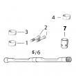
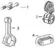
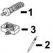
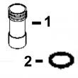
约翰迪尔 4045 4.5T/H 活塞(米) RE521616 排放 2 & 3
|
|
|
发动机和设备型号
|
孔径:
4.19 in 106.5 mm
销径 Ø:
1.6250 in (+/- .0002) = 41mm
|
|
|
强鹿JOHN DEERE柴油机配件、发动机配件、发电机组:
P124866、P124867、P551130、P777638、P181099、P772579、P827653、P771548、P771548、P827653、P772579、P772580、P829333、P13194、P550388、C125017、C125004、P772579、C085001、C085002、C085003、C085004、ECB105012、C105003、AF1913、AF4539、C105004、RE533026/
强鹿JOHN DEERE柴油机配件、发动机配件、发电机组:
H0000351、ECC105017、C105003、ECC105028、ECC065003、B125003、ECB125011,RE522528、RE519774、RE532628、RE518176、RE507980、RE518503、RE522515、RE504836、RE509031、RE509032、RE59754、RE507284、RE59754、RE519626、RE518977、RE508202、RE58935
(cd3029df,cd4039df/tf,cd4045tf,cd6059tf,cd6068tf) pc2450 (20-jan-98) 35-9 pn=271 2c10 injection system fuel injection pump, linkage pompe d’injection, timonerie einspritzpumpe, gestaenge pompa d’iniezione, tiranteria bomba de inyeccion, varillaje insprutningspumpe, laenkage cd37292 -un-17feb95 a engine l key part no- part name qty serial no- l remarks 1 r70513 screw 1 x 2 t17950 retainer 1 x 3 t17949 spring 1 x 4 t19858 lever 1 x 5 t19860 strap 1 x 6 t11917 screw 1 x 7 t19861 spacer 1 x 35-10 genset power units (cd3029df,cd4039df/tf,cd4045tf,cd6059tf,cd6068tf) pc2450 (30-nov-95) pn=272 2c11 injection system fuel injection pump, heavy-duty solenoid (energized to run) pompe d’injection, solenoide haute energie (stop par manque de courant) einspritzpumpe, magnetschalter verstaerkte ausfuehrung (abstellen durch stromwegnahme) pompa d’iniezione, solenoide versione rinforzata (arresto eletrico) bomba de inyeccion, solenoide tipo reforzado (corte eletrico) insprutningspump, solenoid forstarkt utforande (elstopp) cd37290 -un-17feb95 a engine l key part no- part name qty serial no- l remarks 1 re37091 kit 1 x (also order t11918) 2 m63431 lock nut 1 x 3 t11918 gasket 1 x 4 t11937 insulator 2 x 5 r48795 sleeve 1 x for spring,res***t,feder, molla,re***te,fjaeder 6 re62240 solenoid 1 x (also order re37091&t11918) (sub for re37089) (stanadyne, 12 volt) re62241 solenoid 1 x (also order re37091&t11918) (sub for re37090) (stanadyne, 24 volt) 7 r81996 label 1 x genset power units (cd3029df,cd4039df/tf,cd4045tf,cd6059tf,cd6068tf) pc2450 (20-jan-98) 35-11 pn=273 injection system memoranda 35-11a genset power units (cd3029df,cd4039df/tf,cd4045tf,cd6059tf,cd6068tf) pc2450 (20-jan-98) pn=274 2c12 injection system fuel lines for fuel inject- pump stanadyne conduites pour pompe d’injection stanadyne leitungen fuer einspritzpumpe stanadyne tubazioni della pompa d’iniez- stanadyne tuberias de bomba de inyeccion stanadyne ledingar for insprutningspump stanadyne cd40403 -un-28nov95 3 0 2 engine 9 key part no- part name qty serial no- d remarks 1 re20898 fuel line 1 -263023 x no-1 2 re20899 fuel line 1 -263023 x no-2 3 re20900 fuel line 1 -263023 x no-3 4 re25933 tube 1 -263023 x 5 re20901 clamp 1 -263023 x 6 re19797 clamp 1 -263023 x 7 19m8560 cap screw 2 -263023 x m6 x 12 genset power units (cd3029df,cd4039df/tf,cd4045tf,cd6059tf,cd6068tf) pc2450 (20-jan-98) 35-11b pn=275 2c13 injection system fuel lines for fuel inject- pump stanadyne conduites pour pompe d’injection stanadyne leitungen fuer einspritzpumpe stanadyne tubazioni della pompa d’iniez- stanadyne tuberias de bomba de inyeccion stanadyne ledingar for insprutningspump stanadyne cd36507 -un-01jan94 3 0 2 engine 9 key part no- part name qty serial no- d remarks 1 re20898 fuel line 1 263024- x no-1 2 re20899 fuel line 1 263024- x no-2 3 re20900 fuel line 1 263024- x no-3 4 ar89839 fuel line 1 263024- x 5 re20901 clamp 1 263024- x 6 re19797 clamp 1 263024- x 35-12 genset power units (cd3029df,cd4039df/tf,cd4045tf,cd6059tf,cd6068tf) pc2450 (20-jan-98) pn=276 2c14 injection system fuel lines for fuel inject- pump stanadyne conduites pour pompe d’injection stanadyne leitungen fuer stanadyne einspritzpumpe tubazioni della pompa d’iniez- stanadyne tuberias de bomba de inyeccion stanadyne ledingar for insprutningspump stanadyne cd37298a -un-28nov95 4 0 3 engine 9 key part no- part name qty serial no- d remarks 1 re43284 fuel line 1 x no-1 2 re43285 fuel line 1 x no-2 3 re43286 fuel line 1 x no-3 4 re43287 fuel line 1 x no-4 5 re25933 tube 1 x 6 19m6614 cap screw 1 x m6 x 12 7 re19799 clamp 1 x 8 re19797 clamp 1 x genset power units (cd3029df,cd4039df/tf,cd4045tf,cd6059tf,cd6068tf) pc2450 (20-jan-98) 35-13 pn=277 2c15 injection system fuel lines for stanadyne fuel injection pump conduites de combustible pour pompe d’injection stanadyne kraftstoffleitungen fuer stanadyne einspritzpumpe tubazioni della pompa d’iniezione stanadyne tuberias de bomba de inyeccion stanadyne breansleledningar for insprutningspump stanadyne cd37293 -un-17feb95 4 0 3 engine 9 key part no- part name qty serial no- t remarks 1 re43284 fuel line 1 x no-1 2 re43285 fuel line 1 x no-2 3 re43286 fuel line 1 x no-3 4 re43287 fuel line 1 x no-4 5 ar89852 fuel line 1 x rear 6 t29969 clamp ar x 7 19m6614 cap screw 2 x m6 x 12 8 re19797 clamp 2 x 9 re19799 clamp 1 x 10 16h658 rivet ar x 1/4" x 5/8" 35-14 genset power units (cd3029df,cd4039df/tf,cd4045tf,cd6059tf,cd6068tf) pc2450 (20-jan-98) pn=278 2c16 injection system fuel lines for stanadyne fuel injection pump conduites de combustible pour pompe d’injection stanadyne kraftstoffleitungen fuer stanadyne einspritzpumpe tubazioni della pompa d’iniezione stanadyne tuberias de bomba de inyeccion stanadyne breansleledningar for insprutningspump stanadyne cd40033 -un-07nov95 4 0 4 engine 5 key part no- part name qty serial no- t remarks 1 re53853 fuel line 1 x 2 re19797 clamp 2 x 3 19m8560 cap screw 1 x m6 x 12 4 re19799 clamp 1 x 5 re57714 fuel line 4 x genset power units (cd3029df,cd4039df/tf,cd4045tf,cd6059tf,cd6068tf) pc2450 (20-jan-98) 35-15 pn=279 2c17 injection system fuel lines for stanadyne fuel injection pump conduites de combustible pour pompe d’injection stanadyne kraftstoffleitungen fuer stanadyne einspritzpumpe tubazioni della pompa d’iniezione stanadyne tuberias de bomba de inyeccion stanadyne breansleledningar for insprutningspump stanadyne cd40503 -un-17feb95 this parts listing is continued 35-16 genset power units (cd3029df,cd4039df/tf,cd4045tf,cd6059tf,cd6068tf) pc2450 (20-jan-98) pn=280 2c18 injection system 6 0 5 engine 9 key part no- part name qty serial no- t remarks 1 re43293 fuel line 1 x 2 re19797 clamp 5 x 3 19m8560 cap screw 7 x m6 x 12 4 re20901 clamp 1 x 5 re19800 clamp 1 x 6 ar89852 fuel line 1 x genset power units (cd3029df,cd4039df/tf,cd4045tf,cd6059tf,cd6068tf) pc2450 (20-jan-98) 35-17 pn=281 2c19 injection system fuel lines for stanadyne fuel injection pump conduites de combustible pour pompe d’injection stanadyne kraftstoffleitungen fuer stanadyne einspritzpumpe tubazioni della pompa d’iniezione stanadyne tuberias de bomba de inyeccion stanadyne breansleledningar for insprutningspump stanadyne cd39517 -un-01jan94 this parts listing is continued 35-18 genset power units (cd3029df,cd4039df/tf,cd4045tf,cd6059tf,cd6068tf) pc2450 (20-jan-98) pn=282 2c20 injection system 6 0 6 engine 8 key part no- part name qty serial no- t remarks 1 re58410 fuel line 1 x 2 re19797 clamp 5 x 3 19m8560 cap screw 7 x m6 x 12 4 re20901 clamp 1 x 5 re19800 clamp 1 x 6 re52899 tube 1 x genset power units (cd3029df,cd4039df/tf,cd4045tf,cd6059tf,cd6068tf) pc2450 (20-jan-98) 35-19 pn=283 2c21 injection system injection nozzle injecteur einspritzduese iniettore inyector insprutare cd39518b -un-23may95 3 0 2 engine 9 key part no- part name qty serial no- d remarks 1 re36935 injection nozzle 3 x (stanadyne 28480) 2 t31174 plug ar x protecting cap,capuchon de protection, schutzkappe,cappucci di protezione, tapa de protecion 3 - washer 1 x tk 3mm (0-120") ord kit re65201 4 - washer 1 x ord kit re65201 5 t24472 plug ar x protecting cap,capuchon de protection, schutzkappe,cappucci di protezione, tapa de protecion 6 r101201 cap screw 3 x 7 r66090 tube 2 x 8 r51937 tube nut 6 x 9 r51936 packing 6 x 10 r71963 tee fitting 1 x 11 - washer 1 x ord kit re65201 12 r79604 tube nut 1 x 13 - fuel line na x 14 16m2605 rivet ar x 0-236" x 0-787" 15 re65201 o-ring kit ar x (sub for r48000, r60746&r79605, this application) 35-20 genset power units (cd3029df,cd4039df/tf,cd4045tf,cd6059tf,cd6068tf) pc2450 (20-jan-98) pn=284 2c22 injection system injection nozzle injecteur einspritzduese iniettore inyector insprutare cd39518b -un-23may95 4 4 4 0 0 0 3 3 4 engine 9 9 5 key part no- part name qty serial no- d t t remarks 1 re36935 injection nozzle 4 x (stanadyne 28480) re36939 injection nozzle 4 x x (stanadyne 28484) 2 t31174 plug ar x x x protecting cap,capuchon de protection, schutzkappe,cappucci di protezione, tapa de protecion 3 - washer 1 x tk 3mm (0-120") ord kit re65201 - washer 1 x x tk 1-9mm (0-075") ord kit re64292 4 - washer 1 x ord kit re65201 - washer 1 x x ord kit re64292 5 t24472 plug ar x x x protecting cap,capuchon de protection, schutzkappe,cappucci di protezione, tapa de protecion 6 r101201 cap screw 4 x x x 7 r66090 tube 3 x x x 8 r51937 tube nut 8 x x x 9 r51936 packing 8 x x x 10 r71963 tee fitting 1 x x x 11 - washer 1 x ord kit re65201 - washer 1 x x ord kit re64292 12 r79604 tube nut 1 x x x 13 - fuel line na x x x 14 16m2605 rivet ar x x x 0-236" x 0-787" 15 re65201 o-ring kit ar x (sub for r48000, r60746&r79605, this application) re64292 o-ring kit ar x x (sub for r48000, r79605&r92352, this application) genset power units (cd3029df,cd4039df/tf,cd4045tf,cd6059tf,cd6068tf) pc2450 (20-jan-98) 35-21 pn=285 2c23 injection system injection nozzle injecteur einspritzduese iniettore inyector insprutare cd39518b -un-23may95 6 6 0 0 5 6 engine 9 8 key part no- part name qty serial no- t t remarks 1 re36939 injection nozzle 6 x x (stanadyne 28484) 2 t31174 plug ar x x protecting cap,capuchon de protection, schutzkappe,cappucci di protezione, tapa de protecion 3 - washer 1 x x tk 1-9mm (0-074") ord kit re64292 4 - washer 1 x x ord kit re64292 5 t24472 plug ar x x protecting cap,capuchon de protection, schutzkappe,cappucci di protezione, tapa de protecion 6 r101201 cap screw 6 x x 7 r66090 tube 5 x x 8 r51937 tube nut 12 x x 9 r51936 packing 12 x x 10 r71963 tee fitting 1 x x 11 - washer 1 x x ord kit re64292 12 r79604 tube nut 1 x x 13 - fuel line na x x 14 16m2605 rivet ar x x 0-236" x 0-787" 15 re64292 o-ring kit ar x x (sub for r48000, r79605&r92352, this application) 35-22 genset power units (cd3029df,cd4039df/tf,cd4045tf,cd6059tf,cd6068tf) pc2450 (20-jan-98) pn=286 2d2 starter starter, 2 holes mounting flange, r-h- code 3008, 3025 demarreur, bride de fixation 2 trous a droite, code 3008, 3025 starter, befestigungsflansch mit 2 bohrungen, rechts, kode 3008, 3025 motorino d’avviamento, flangia di montaggio a 2 fori, a destra, codice 3008, 3025 motor de arranque, brida de sujecion 2 agujeros a la derecha, codigo 3008, 3025 startmotor, monterings flens med 2 haal, hoeger sida, koden 3008, 3025 cd40146 -un-06dec95 3 0 2 engine 9 key part no- part name qty serial no- d remarks 1 14h812 nut 1 x 3/8" 2 12h304 lock washer 2 x 3/8" 3 l39334 stud 1 x 3/8" x 1-693" 4 re60384 starter 1 x (iskra azj 3181)(12 volt -3-1kw)(3008) (order re500733) re500733 motor 1 x (iskra azj 3283)(12 volt -3-1kw)(3008) re67086 starter 1 x (iskra azj3214)(24 volt - 4 kw)(3025) (also order rt7700040288&r116617) 5 19h1732 cap screw 1 x 3/8" x 1-1/4" 6 14m7140 nut 1 x m10 7 12m7013 lock washer 1 x 10-200 mm 8 r116617 label 1 x bypass start,demarrage court-circuite, anlass-sicherheitschalter,accensione in folle,arranque por derivacion,startspear 9 rt7700040288 cover 1 x (3025) genset power units (cd3029df,cd4039df/tf,cd4045tf,cd6059tf,cd6068tf) pc2450 (20-jan-98) 40-1 pn=287 2d3 starter starter, components, code 3008, 3025 demarreur, composants, code 3008, 3025 starter, komponenten, kode 3008, 3025 motorino d’avviamento, componenti, codici 3008, 3025 motor de arranque, componentes, codigo 3008, 3025 startmotor, endast, koden 3008, 3025 cd40138 -un-02dec94 3 0 2 engine 9 key part no- part name qty serial no- d remarks 1 re62665 solenoid 1 x (a) (3008) re500721 solenoid 1 x (a) (3025) 2 re62666 shifter 1 x 3 re62667 kit 1 x w/ (2) carbon brush conductor,balai, kohlebuerste,spazzole di carbone, escobilla,kolborste (3008) re500722 kit 1 x w/ (2) carbon brush conductor,balai, kohlebuerste,spazzole di carbone, escobilla,kolborste (3025) 4 re62668 bendix drive 1 x 5 re62669 kit 1 x (3008) re62673 kit 1 x (3025) (a) see your authorized starter repair station for parts not listed 40-2 genset power units临沂美国强鹿柴油机止推瓦RE65168哪家买,拉萨强鹿柴油机主轴瓦RE65165供货商,桂林JohnDeere进气门R84618厂家供应,三沙约翰迪尔4045柴油机气门导管厂家供货,松原JohnDeere排气门导管R119132批发商,日照发动机内部修理套件约翰迪尔强鹿公司,六安约翰迪尔柴油机节温器AR48675批发价,天津约翰迪尔re509672强鹿农机机油滤芯哪家好,汕头美国JohnDeere机油泵RE527933哪家买,本溪约翰迪尔活塞缸套组件RE64509厂家供货,阿拉善强鹿4045柴油机平衡轴铜套TR115299信息,定西JohnDeere柴油机四配套DZ10211厂家价格,大连约翰迪尔RE531703滤芯批发,福州约翰迪尔6081柴油机气门锁夹厂家批发,白城美国强鹿配件实时报价一级代理,抚顺约翰迪尔6068柴油机机油底壳垫片厂家价格, (cd3029df,cd4039df/tf,cd4045tf,cd6059tf,cd6068tf) pc2450 (20-jan-98) pn=288 2d4 starter starter, 2 holes mounting flange, r-h- code 3014 demarreur, bride de fixation 2 trous a droite, code 3014 starter, befestigungsflansch mit 2 bohrungen, rechts, kode 3014 motorino d’avviamento, flangia di montaggio a 2 fori, a destra, codice 3014 motor de arranque, brida de sujecion 2 agujeros a la derecha, codigo 3014 startmotor, monterings flens med 2 haal, hoeger sida, koden 3014 tp41959 -un-01jan94 3 0 2 engine 9 key part no- part name qty serial no- d remarks 1 t146102 label 1 -263023 x 2 h113196 tie band 1 -263023 x lgth 1016mm (40") r44302 tie band 2 -263023 x lgth 171mm (6-3/4") 3 re50096 kit 1 -263023 x 4 re52120 kit 1 -263023 x (24v - 5kw) 5 12m7013 lock washer 1 -263023 x 10-200 mm 6 14m7274 nut 1 -263023 x m10 7 14m7297 nut 1 -263023 x m5 8 12m7064 lock washer 1 -263023 x 5-100 mm 9 l39334 stud 1 -263023 x 3/8" x lgth 43mm (1-69") up 19h3239 cap screw 1 -263023 x 3/8" x 1-1/4", low 10 12h304 lock washer 2 -263023 x 3/8" genset power units (cd3029df,cd4039df/tf,cd4045tf,cd6059tf,cd6068tf) pc2450 (20-jan-98) 40-3 pn=289 2d5 starter starter, components, code 3014 demarreur, composants, code 3014 starter,komponenten, kode 3014 motorino d’avviamento, componenti, codici 3014 motor de arranque, componentes, codigo 3014 startmotor, endast, koden 3014 tp41960 -un-01jan94 this parts listing is continued 40-4 genset power units (cd3029df,cd4039df/tf,cd4045tf,cd6059tf,cd6068tf) pc2450 (20-jan-98) pn=290 2d6 starter 3 0 2 engine 9 key part no- part name qty serial no- d remarks 1 t146102 label 1 -263023 x 2 h113196 tie band 1 -263023 x lgth 1016 mm (40") r44302 tie band 2 -263023 x lgth 171 mm(6-3/4") 3 re50096 kit 1 -263023 x 4 re52122 switch 1 -263023 x 5 r112923 bushing 1 -263023 x 6 r112922 stop 1 -263023 x 7 re52124 bendix drive 1 -263023 x 8 re52125 kit 1 -263023 x 9 r112926 o-ring 1 -263023 x 10 re52120 kit 1 -263023 x (24v - 5kw) 11 12m7013 lock washer 1 -263023 x 10-200 mm 12 14m7274 nut 1 -263023 x m10 13 12m7064 lock washer 1 -263023 x 5-100 mm 14 14m7297 nut 1 -263023 x m5 genset power units (cd3029df,cd4039df/tf,cd4045tf,cd6059tf,cd6068tf) pc2450 (20-jan-98) 40-5 pn=291 2d7 starter starter, 3 holes mounting flange, r-h- code 3008,3009,3016,3026 demarreur, bride de fixation 3 trous a droite, code 3008,3009,3016,3026 starter, befestigungsflansch mit 3 bohrungen, rechts, kode 3008,3009,3016,3026 motorino d’avviamento, flangia di montaggio a 3 fori, a destra, codice 3008,3009,3016,3026 motor de arranque, brida de sujecion 3 agujeros a la derecha, codigo 3008,3009,3016,3026 startmotor, monterings flens med 3 haal, hoeger sida, koden 3008,3009,3016,3026 cd40612 -un-09feb96 3 4 4 0 0 0 2 3 3 engine 9 9 9 key part no- part name qty serial no- d d t remarks 1 14h812 nut 1 x x x 3/8" 2 12h304 lock washer 3 x x x 3/8" 3 l39334 stud 1 x x x 3/8" x 1-693" 4 re59010 motor 1 x x x (iskra azj 3190, 12 volt - 3-0 kw) (also order rt7700040288&r116617) (3008/3009/3016) re67087 starter 1 x x x (iskra azj 3225)(24 volt - 4 kw)(3026) (also order rt7700040288&r116617) 5 19h1732 cap screw 2 x x x 3/8" x 1-1/4" 6 14m7140 nut 1 x x x m10 7 12m7013 lock washer 1 x x x 10-200 mm 8 r116617 label 1 x x x bypass start,demarrage court-circuite, anlass-sicherheitschalter,accensione in folle,arranque por derivacion,startspear 9 rt7700040288 cover 1 x x x 40-6 genset power units (cd3029df,cd4039df/tf,cd4045tf,cd6059tf,cd6068tf) pc2450 (20-jan-98) pn=292 2d8 starter components for starter, code 3008,3009,3016,3026 composants pour demarreur, code 3008,3009,3016,3026 komponenten fuer starter, kode 3008,3009,3016,3026 componenti per motorino d’avviamento, codici 3008,3009,3016,3026 componentes para motor de arranque, codigo 3008,3009,3016,3026 endast foer startmotor, koden 3008,3009,3016,3026 cd40138 -un-02dec94 3 4 4 0 0 0 2 3 3 engine 9 9 9 key part no- part name qty serial no- d d t remarks 1 re62665 solenoid 1 x x x (a) (3008,3009,3016) re500721 solenoid 1 x x x (a) (3026) 2 re62666 shifter 1 x x x 3 re62670 carbon brush conductor 1 x x x w/ (2) carbon brush conductor,balai, kohlebuerste, spazzole di carbone, escobilla, kolborste (3008,3009,3016) re500722 carbon brush conductor 1 x x x w/ (2) carbon brush conductor,balai, kohlebuerste, spazzole di carbone, escobilla, kolborste (3026) 4 re62672 bendix drive 1 x x x 5 re62673 kit 1 x x x (a) see your authorized starter repair station for parts not listed genset power units (cd3029df,cd4039df/tf,cd4045tf,cd6059tf,cd6068tf) pc2450 (20-jan-98) 40-7 pn=293 2d9 starter starter, 3 holes mounting flange, r-h- code 3008,3009,3020,3026 demarreur, bride de fixation 3 trous a droite, code 3008,3009,3020,3026 starter, befestigungsflansch mit 3 bohrungen, rechts, kode 3008,3009,3020,3026 motorino d’avviamento, flangia di montaggio a 3 fori, a destra, codice 3008,3009,3020,3026 motor de arranque, brida de sujecion 3 agujeros a la derecha, codigo 3008,3009,3020,3026 startmotor, monterings flens med 3 haal, hoeger sida, koden 3008,3009,3020,3026 cd40612 -un-09feb96 4 6 6 0 0 0 4 5 6 engine 5 9 8 key part no- part name qty serial no- t t t remarks 1 14h812 nut 1 x x x 3/8" 2 12h304 lock washer 3 x x x 3/8" 3 l39334 stud 1 x x x 3/8" x 1-693" 4 re59010 motor 1 x x x (iskra azj 3190, 12 volt - 3-0 kw) (also order rt7700040288&r116617) (3008/3009) re67087 starter 1 x x x (iskra 24volt - 4-0 kw) (also order rt7700040288&r116617) (3026) re30493 starter 1 x (r- bosch a001812394 2a, 12volt-2-7kw) (3020) 5 19h1732 cap screw 2 x x x 3/8" x 1-1/4" 6 14m7140 nut 1 x x x m10 7 12m7013 lock washer 1 x x x 10-200 mm 8 r116617 label 1 x x x bypass start,demarrage court-circuite, anlass-sicherheitschalter,accensione in folle,arranque por derivacion,startspear 9 rt7700040288 cover 1 x x x (3008,3009,3026) 40-8 genset power units (cd3029df,cd4039df/tf,cd4045tf,cd6059tf,cd6068tf) pc2450 (20-jan-98) pn=294 2d10 starter components for starter, code 3008,3009,3020,3026 composants pour demarreur, code 3008,3009,3020,3026 komponenten fuer starter, kode 3008,3009,3020,3026 componenti per motorino d’avviamento, codici 3008,3009,3020,3026 componentes para motor de arranque, codigo 3008,3009,3020,3026 endast foer startmotor, koden 3008,3009,3020,3026 cd40138 -un-02dec94 4 6 6 0 0 0 4 5 6 engine 5 9 8 key part no- part name qty serial no- t t t remarks 1 re62665 solenoid 1 x x x (a) (3008,3009) re500721 solenoid 1 x x x (a) (3026) al55046 solenoid 1 x (a) (3020) 2 re62666 shifter 1 x x x (3008,3009,3026) al25273 shifter 1 x (also order al70855&14m7151 and 12m7065) (3020) 3 re62670 carbon brush conductor 1 x x x w/ (2) carbon brush conductor,balai, kohlebuerste, spazzole di carbone, escobilla, kolborste (3008,3009) re500722 carbon brush conductor 1 x x x w/ (2) carbon brush conductor,balai, kohlebuerste, spazzole di carbone, escobilla, kolborste (3026) al55047 carbon brush conductor 1 x w/ (4) carbon brush conductor, balai, kohlebuerste, spazzole di carbone, escobilla, kolborste (3020) 4 re62672 bendix drive 1 x x x (3008,3009,3026) al63095 bushing 1 x (3020) 5 re62673 kit 1 x x x (3008,3009,3026) al70855 kit 1 x (3020) (a) see your authorized starter repair station for parts not listed genset power units (cd3029df,cd4039df/tf,cd4045tf,cd6059tf,cd6068tf) pc2450 (20-jan-98) 40-9 pn=295 2d11 starter starting motor,3 holes mounting flange, r-h- code 3015 (early design) demarreur, bride de fixation 3 trous a droite, code 3015 (conception ancienne) starter, befestigungsflansch mit 3 bohrungen, rechts, kode 3015 (aeltere bauweise) motorino d’avviamento, flangia di montaggio a 3 fori, a destra, codice 3015 (vecchio modello) motor de arranque, brida de sujecion 3 agujeros a la derecha, codigo 3015 (diseno anterior) startmotor, koden 3015 (tidgare utfoerande) cda38123 -un-17feb95 this parts listing is continued 40-10 genset power units (cd3029df,cd4039df/tf,cd4045tf,cd6059tf,cd6068tf) pc2450 (20-jan-98) pn=296 2d12 starter 6 0 6 engine 8 key part no- part name qty serial no- t remarks 1 r55396 stud 1 x 2 12h304 lock washer 2 x 3/8" 3 14h812 nut 1 x 3/8" 4 19h2545 cap screw 1 x 3/8" x 1-3/8" 5 r53108 gasket 1 x 6 - starter 1 x (denso nd128000-7240, 24volt - 7-5kw) order re43422 7 re43421 kit 1 x 8 r104677 bushing 1 x 9 r104646 screw 1 x 10 r104676 shim 1 x 11 r104647 cover 1 x 12 r44302 tie band 1 x 13 r76477 tie band 1 x 14 t84409 safety sign ar x (english) t84410 label ar x (espanol) t84411 label ar x (francais) t84412 label ar x (deutsch) t84413 label ar x (italiano) t84578 label ar x (english/francais) 15 re43422 kit 1 x (denso nd128000-7240, 24volt - 7-5kw) (sub re70961) 16 r116617 label 1 x genset power units (cd3029df,cd4039df/tf,cd4045tf,cd6059tf,cd6068tf) pc2450 (20-jan-98) 40-11 pn=297 2d13 starter starting motor, components, code 3015 (early design) demarreur, composants, code 3015 (conception ancienne) starter,komponenten, kode 3015 (aeltere bauweise) motorino d’avviamento, componenti, codici 3015 (vecchio modello) motor de arranque, componentes, codigo 3015 (diseno anterior) startmotor, endast, koden 3015 (tidgare utfoerande) tp28463 -un-01jan94 this parts listing is continued 40-12 genset power units (cd3029df,cd4039df/tf,cd4045tf,cd6059tf,cd6068tf) pc2450 (20-jan-98) pn=298 2d14 starter 6 0 6 engine 8 key part no- part name qty serial no- t remarks 1 re39251 needle bearing 2 x 2 r50902 snap ring 1 x 3 re39249 clutch 1 x 4 r50901 washer 1 x 5 r100513 cover 1 x 6 re39242 switch 1 x 7 r100511 o-ring 1 x 8 r100509 bushing 1 x 9 re39244 field winding coil 1 x 10 re39246 armature 1 x 11 re39250 carbon brush holder 1 x 12 r100512 o-ring 1 x 13 r100508 screw 1 x 14 re39248 brush 4 x genset power units (cd3029df,cd4039df/tf,cd4045tf,cd6059tf,cd6068tf) pc2450 (20-jan-98) 40-13 pn=299 2d15 starter starting motor,3 holes mounting flange, r-h- code 3015 (late design) demarreur, bride de fixation 3 trous a droite, code 3015 (conception recente) starter, befestigungsflansch mit 3 bohrungen, rechts, kode 3015 (neuere bauweise) motorino d’avviamento, flangia di montaggio a 3 fori, a destra, codice 3015 (nuevo modello) motor de arranque, brida de sujecion 3 agujeros a la derecha, codigo 3015 (diseno recente) startmotor, koden 3015 (senare utfoerande) tp53476 -un-28apr97 this parts listing is continued 40-14 genset power units (cd3029df,cd4039df/tf,cd4045tf,cd6059tf,cd6068tf) pc2450 (20-jan-98) pn=300 2d16 starter 6 0 6 engine 8 key part no- part name qty serial no- t remarks 1 re70756 kit 1 x 2 r96703 tie band 1 x 3 t146102 label 1 x 4 r135509 seal 1 x 5 r135510 o-ring 1 x 6 re70681 switch 1 x 7 re70487 clutch 1 x 8 re71256 screw, with washer 1 x 9 19h1732 cap screw 2 x 3/8" x 1-1/4", (use with (2) 24m7028) l39334 stud 1 x (use with (2) n10215) 10 re70961 kit 1 x (denso 24volt-7-8kw) (sub for re43422 and re65173) genset power units (cd3029df,cd4039df/tf,cd4045tf,cd6059tf,cd6068tf) pc2450 (20-jan-98) 40-15 pn=301 2d18 alternator alternator, code 3106,3112,3119,3121 alternateur, code 3106,3112,3119,3121 drehstromgenerator, kode 3106,3112,3119,3121 alternatore, codici 3106,3112,3119,3121 alternador, codigo 3106,3112,3119,3121 vaexelstroemsgenerator, koden 3106,3112,3119,3121 cd40309 -un-17oct94 3 4 4 0 0 0 2 3 3 engine 9 9 9 key part no- part name qty serial no- d d t remarks 1 19h2661 cap screw 1 x x x 5/16" x 1-3/8" 2 24h1292 washer 2 x x x 11/32" x 3/4" x 0-120" 3 r121008 shield 1 x x x 4 12m7056 lock washer 1 x x x 8-100 mm 5 14h785 nut 1 x x x 5/16" 6 re62627 connector 1 x x x 47 ohms, 12v, (3106,3112) re71583 connector 1 x x x 82 ohms, 24v, (3119,3121) 7 19h1921 cap screw 1 -263023 x 5/16" x 3-1/4", (3106) 19h1897 cap screw 1 263024- x 5/16" x 3-3/4", (3112) 19h1921 cap screw 1 x x 5/16" x 3-1/4", (3106) 8 re57960 alternator 1 -263023 x (a) (magneton 443113516760,12volt - 55amp) (3106) re57960 alternator 1 263024- x (a) (magneton 443113516760,12volt - 55amp) (3112) re70779 alternator 1 263024- x (a) (magneton 443113516875,24volt - 40amp) (3121) re57960 alternator 1 x x (a) (magneton 443113516760,12volt - 55amp) (3106) re70779 alternator 1 x x (a) (magneton 443113516875,24volt - 40amp) (3119) 9 r134417 sheave 1 x x x 11/16" x od 85mm, (sub for r122154) 10 14m7265 lock nut 2 x x x m5 11 14m7165 lock nut 1 x x x m6 (a) see your authorized repair station for parts not listed 50-2 genset power units (cd3029df,cd4039df/tf,cd4045tf,cd6059tf,cd6068tf) pc2450 (20-jan-98) pn=302 2d19 alternator alternator, code 3106 alternateur, code 3106 drehstromgenerator, kode 3106 alternatore, codici 3106 alternador, codigo 3106 vaexelstroemsgenerator, koden 3106 cd40015 -un-20jul95 3 4 4 0 0 0 2 3 3 engine 9 9 9 key part no- part name qty serial no- d d t remarks 1 19h2661 cap screw 1 x x x 5/16" x 1-3/8" 2 24h1292 washer 2 x x x 11/32" x 3/4" x 0-120" 3 14h785 nut 2 x x x 5/16" 4 19h1897 cap screw 1 x x x 5/16" x 3-3/4" 5 14m7158 nut 1 x x x m16 6 12m7134 lock washer 1 x x x 16-200 mm 7 r122154 sheave 1 x x x 8 l77042 fan 1 x x x 9 al81436 alternator 1 x x x (a) (r-bosch 0120488290, 12volt-55amp) assy,incl-keys 10-13 10 al30423 capacitor 1 x x x 11 12m7075 washer 1 x x x 5-300 x 11 x 0-500 mm 12 21m7198 screw 1 x x x m5 x 8 13 al65077 regulator 1 x x x 14 14m7265 lock nut 1 x x x m5 15 14m7165 lock nut 1 x x x m6 (a) see your authorized repair station for parts not listed genset power units (cd3029df,cd4039df/tf,cd4045tf,cd6059tf,cd6068tf) pc2450 (20-jan-98) 50-3 pn=303 2d20 alternator alternator, code 3141 alternateur, code 3141 drehstromgenerator, kode 3141 alternatore, codici 3141 alternador, codigo 3141 vaexelstromsgenerator, koden 3141 cd37801a -un-15sep95 3 4 4 0 0 0 2 3 3 engine 9 9 9 key part no- part name qty serial no- d d t remarks 1 r87797 sheave 1 x x x 11/16" x od 101mm (3-97") 2 r50659 fan 1 x x x 3 at130930 alternator 1 x x x (a) (delco remy 1101285, 24volt-40 amp) 4 ar55283 wiring harness 1 x x x 5 14m7165 lock nut 1 x x x m6 6 19m7163 cap screw 1 x x x m8 x 25 7 12m7065 lock washer 1 x x x 8-100 mm 8 24m7055 washer 1 x x x 8-400 x 16 x 1-600 mm 9 r56012 shield 1 x x x 10 19m7329 cap screw 1 x x x m10 x 75 11 28h2547 spacer na x x x 0-423" x 0-675" x 1" 12 12m7066 lock washer 1 x x x 10-200 mm 13 14m7274 nut 1 x x x m10 (a) see your authorized repair station for parts not listed 50-4 genset power units (cd3029df,cd4039df/tf,cd4045tf,cd6059tf,cd6068tf) pc2450 (20-jan-98) pn=304 2d21 alternator alternator, code 3106,3119 alternateur, code 3106,3119 drehstromgenerator, kode 3106,3119 alternatore, codici 3106,3119 alternador, codigo 3106,3119 vaexelstroemsgenerator, koden 3106,3119 cd40309 -un-17oct94 4 0 4 engine 5 key part no- part name qty serial no- t remarks 1 19h2661 cap screw 1 x 5/16" x 1-3/8" 2 24h1292 washer 2 x 11/32" x 3/4" x 0-120" 3 r121008 shield 1 x 4 12m7056 lock washer 1 x 8-100 mm 5 14h785 nut 1 x 5/16" 6 re62627 connector 1 x 47 ohm 7 19h1921 cap screw 1 x 5/16" x 3-1/4" 8 re57960 alternator 1 x (a) (magneton 443113516760,12volt-55amp) (3106), assy re70779 alternator 1 x (a) (magneton 443113516875,24volt-40amp) (3119) 9 r122154 sheave 1 x 11/16" x od 98mm (3-85") 10 14m7265 lock nut 2 x m5 11 14m7165 lock nut 1 x m6 (a) see your authorized repair station for parts not listed genset power units (cd3029df,cd4039df/tf,cd4045tf,cd6059tf,cd6068tf) pc2450 (20-jan-98) 50-5 pn=305 2d22 alternator alternator, code 3107,3120 alternateur, code 3107,3120 drehstromgenerator, kode 3107,3120 alternatore, codice 3107,3120 alternador, codigo 3107,3120 vaexelstroemsgenerator, koden 3107,3120 cd40016 -un-25oct95 6 6 0 0 5 6 engine 9 8 key part no- part name qty serial no- t t remarks 1 19h2661 cap screw 1 x x 5/16" x 1-3/8" 2 24h1292 washer 2 x x 11/32" x 3/4" x 0-120" 3 r121008 shield 1 x x 4 12m7056 lock washer 1 x x 8-100 mm 5 14h785 nut 1 x x 5/16" 6 re62627 connector 1 x x 47 ohm 7 19h1897 cap screw 1 x x 5/16" x 3-3/4" 8 - alternator 1 x x (a) (magneton 443113516762,12volt-55amp) order re57960 + r122155 (3107) re57960 alternator 1 x x (a) (magneton 443213516762,12volt-55amp) (also order r122155) (3107) - alternator 1 x x (a) (magneton 443113516875,24volt-40amp) order re57779 + r122155 (3120) re70779 alternator 1 x x (a) (magneton 443113516875,24volt-40amp) (also order r122155) (3120) 9 r122155 sheave 1 x x 1/2" x od 80mm (3-14") 10 14m7265 lock nut 2 x x m5 11 14m7165 lock nut 1 x x m6 (a) see your authorized repair station for parts not listed 50-6 genset power units (cd3029df,cd4039df/tf,cd4045tf,cd6059tf,cd6068tf) pc2450 (20-jan-98) pn=306 2d23 alternator alternator, code 3140 alternateur, code 3140 drehstromgenerator, kode 3140 alternatore, codici 3140 alternador, codigo 3140 vaexelstroemsgenerator, koden 3140 cd37802a -un-15sep95 6 6 0 0 5 6 engine 9 8 key part no- part name qty serial no- t t remarks 1 t42171 pulley 1 x x 1/2" x od 81mm (3-18") 2 r50659 fan 1 x x 3 at130930 alternator 1 x x (a) (delco remy 1101285, 24volt-40amp) 4 ar55283 wiring harness 1 x x 5 14m7165 lock nut 1 x x m6 6 19m7163 cap screw 1 x x m8 x 25, (sub for r56012) 7 12m7056 lock washer 1 x x 8-100 mm 8 24m7055 washer 1 x x 8-400 x 16 x 1-600 mm 9 r122848 shield 1 x x 10 19m7329 cap screw 1 x x m10 x 75 11 28h2547 spacer 1 x x 0-423" x 0-675" x 1" 12 12m7066 lock washer 1 x x 10-200 mm 13 14m7274 nut 1 x x m10 (a) see your authorized repair station for parts not listed genset power units (cd3029df,cd4039df/tf,cd4045tf,cd6059tf,cd6068tf) pc2450 (20-jan-98) 50-7 pn=307 2d24 alternator alternator, components, for delco remy 24v alternateur, composants, pour delco remy 24v drehstromgenerator, komponenten, fuer delco remy 24v alternatore, componenti, per delco remy 24v alternador, componentes, para delco remy 24v vaexelstroemsgenerator, for delco remy 24v tp19769 -un-01jan94 this parts listing is continued 50-8 genset power units (cd3029df,cd4039df/tf,cd4045tf,cd6059tf,cd6068tf) pc2450 (20-jan-98) pn=308 2d25 alternator a engine l key part no- part name qty serial no- l remarks 1 - nut 1 x 2 14m7303 flange nut 1 x m6 3 r60492 fan 1 x 4 - bushing 1 x 5 ar77851 roller bearing 2 x 6 26h72 shaft key 1 x 1/8" x 5/8" 7 - ring 1 x 8 at129531 diode 1 x 9 re20036 regulator 1 x 10 at129533 holder 1 x 11 - gasket 1 x 12 t103118 cover 1 x 13 12h356 lock washer 1 x 1/4" 14 ty6752 alternator 1 x at130930 alternator 1 x - t123729 roller bearing 1 x genset power units (cd3029df,cd4039df/tf,cd4045tf,cd6059tf,cd6068tf) pc2450 (20-jan-98) 50-9 pn=309 2e1 alternator alternator, components, for magneton 12v / 24v alternateur, composants, pour magneton 12v / 24v drehstromgenerator, komponenten, fuer magneton 12v / 24v alternatore, componenti, per magneton 12v / 24v alternador, componentes, para magneton 12v / 24v vaexelstroemsgenerator, for magneton 12v / 24v cda40304 -un-20jul95 a engine l key part no- part name qty serial no- l remarks 1 re63497 regulator 1 x std (12 volt) re69380 regulator ar x (- 0-35 volt)(w/ 12 volt,appl) narrower range, plage de regulation etroite, enger regelbereich, banda de regulacion estrecha re500068 regulator 1 x std (24 volt) 2 re58515 diode 1 x (12 volt) re500066 diode 1 x (24 volt) 50-10 genset power units (cd3029df,cd4039df/tf,cd4045tf,cd6059tf,cd6068tf) pc2450 (20-jan-98) pn=310 2e2 alternator alternator adjusting strap, code 6201-6222 bride de reglage de l’alternateur, code 6201-6222 drehstromgenerator-einstellasche, kode 6201-6222 fascetta regolabile dell’alternatore, codici 6201-6222 pletina de ajuste del alternador, codigo 6201-6222 oeversaettn-ej tillgaenglig for axelstromsgenerator, koden 6201-6222 cd40506 -un-17feb95 a engine l key part no- part name qty serial no- l remarks 1 19h1819 cap screw ar x 3/8" x 2-1/8" 19h1944 cap screw ar x 3/8" x 2-3/4" 19h2458 cap screw ar x 3/8" x 3" 19h2023 cap screw ar x 3/8" x 3-1/4" 19h3065 cap screw ar x 3/8" x 2" 2 12h304 lock washer 1 x 3/8" 3 r99257 washer ar x a = 5mm (0-19") 4 r91453 strap 1 x a = 81mm (3-18") (delco remy) t32853 strap 1 x a = 104mm (4-09") (magneton,r-bosch) 5 a147r lock washer ar x 13/32" x 7/8" x 3/16" 24h1304 washer ar x 13/32" x 23/32" x 0-120" 28h1517 washer ar x 0-493" x 0-675" x 1/4" t14040 bushing ar x tk 19mm (0-74") r64449 bushing ar x tk 25-4mm (1") genset power units (cd3029df,cd4039df/tf,cd4045tf,cd6059tf,cd6068tf) pc2450 (20-jan-98) 50-11 pn=311 2e3 alternator alternator brackets, code 6206 (delco remy) supports d’alternateur, code 6206 (delco remy) drehstromgeneratorkonsole, kode 6206 (delco remy) staffa dell’alternatore, codici 6206 (delco remy) soporte del alternador, codigo 6206 (delco remy) konsol for vaxelstromsgenerator, koden 6206 (delco remy) cd37223a -un-17feb95 3 4 4 0 0 0 2 3 3 engine 9 9 9 key part no- part name qty serial no- d d t remarks 1 r64449 bushing 2 x x x tk 25-4mm (1") 2 19h2700 cap screw 2 x x x 3/8" x 4-1/2" 3 t20202 bracket 1 x x x front 4 r59962 bracket 1 x x x rear 5 n10215 lock nut 2 x x x 3/8" 6 24m7096 washer 2 x x x 10-500 x 18 x 1-600 mm 50-12 genset power units (cd3029df,cd4039df/tf,cd4045tf,cd6059tf,cd6068tf) pc2450 (20-jan-98) pn=312 2e4 alternator alternator brackets, code 6218 (magneton,r-bosch) supports d’alternateur, code 6218 (magneton,r-bosch) drehstromgeneratorkonsole, kode 6218 (magneton,r-bosch) staffa dell’alternatore, codici 6218 (magneton,r-bosch) soporte del alternador, codigo 6218 (magneton,r-bosch) konsol for vaxelstromsgenerator, koden 6218 (magneton,r-bosch) cd40017 -un-20jul95 3 4 0 0 2 3 engine 9 9 key part no- part name qty serial no- d d remarks 1 19h1912 cap screw 2 x x 3/8" x 3-1/2" 2 24h1303 washer 2 x x 13/32" x 11/16" x 0-065" 3 r126389 bracket 2 x x 4 r64449 bushing 2 x x tk 25-4mm (1") 5 t20280 washer 1 x x tk 9mm (0-354") 6 n10215 lock nut 2 x x 3/8", rear genset power units (cd3029df,cd4039df/tf,cd4045tf,cd6059tf,cd6068tf) pc2450 (20-jan-98) 50-13 pn=313 2e5 alternator alternator brackets, code 6201 (delco remy) supports d’alternateur, code 6201 (delco remy) drehstromgeneratorkonsole, kode 6201 (delco remy) staffa dell’alternatore, codici 6201 (delco remy) soporte del alternador, codigo 6201 (delco remy) konsol for vaxelstromsgenerator, koden 6201 (delco remy) cd40507 -un-17feb95 6 0 5 engine 9 key part no- part name qty serial no- t remarks 1 r64449 bushing 2 x tk 25-4mm (1") 2 19h1697 cap screw 2 x 3/8" x 4" 3 r109878 bracket 1 x front 4 r57260 bracket 1 x rear 5 n10215 lock nut 2 x 3/8" 50-14 genset power units (cd3029df,cd4039df/tf,cd4045tf,cd6059tf,cd6068tf) pc2450 (20-jan-98) pn=314 2e6 alternator alternator brackets, code 6222 supports d’alternateur, code 6222 drehstromgeneratorkonsole, kode 6222 staffa dell’alternatore, codici 6222 soporte del alternador, codigo 6222 konsol for vaxelstroemsgenerator, koden 6222 cd39629 -un-17aug95 a engine l key part no- part name qty serial no- l remarks 1 19h2815 cap screw 1 x 3/8" x 2-1/4" 2 24m7106 washer 3 x 10 x 18 x 2-500 mm 3 19h2458 cap screw 1 x 3/8" x 3" 4 r87249 bracket 1 x front 5 r64449 bushing 1 x tk 25-4mm (1") 6 r60828 bracket 1 x rear 7 19h2284 cap screw 2 x 3/8" x 7/8" 8 24h1305 washer 2 x 13/32" x 13/16" x 0-065" genset power units (cd3029df,cd4039df/tf,cd4045tf,cd6059tf,cd6068tf) pc2450 (20-jan-98) 50-15 pn=315 2e8 air cleaner air cleaner, code 1802,1804 filtre a air, code 1802,1804 luftfilter-zusb- kode 1802,1804 depuratore d’aria, codici 1802,1804 filtro de aire, codigo 1802,1804 luftrenare, koden 1802,1804 cd40019 -un-22aug95 this parts listing is continued 60-2 genset power units 河北石家庄桥西Cat卡特发动机配件价格供应服务商?,北京平谷Perkins4016柴油机气压传感器认准指定代理商,塔城托里县三菱发动机配件深圳价格透明,西安未央帕金斯1306柴油发动机启动马达最新报价,张掖甘州三菱S6R2-PTAA-C零部件专业的服务,淮南潘集大宇发电机组零配件谁知道价格?,河北石家庄行唐县perkins增压器总成SE652CJ快捷的交货方式,山西太原约翰迪尔高压油泵什么地方有?,loose/corroded wire connections clean&tighten connections. viscosity of engine oil too high use proper viscosity oil. ctm67 (24sep02) 21-19 oem engine acces***ies 092402 pn=71 continued on next page electrical system diagnostics, tests&operation 21 20 rg,ctm67,g21,8 –19–19nov93–2/2 symptom problem solution starter operative; rest of blown fuse replace fuse. (see check fuses in electrical system inoperative this group.) defective magnetic safety switch test safety switch. (see test magnetic switch in this group.) ctm67 (24sep02) 21-20 oem engine acces***ies 092402 pn=72 electrical system diagnostics, tests&operation 21 21 rg,rg34710,5601 –19–07jan02–1/4 checking fuses in instrument panels rg4493 –un–14dec88 north american ( —1998) standard instrument panel shown rg4496a –un–01jun01 north american ( —1998) standard instrument panel shown rg11937 –un–17oct01 north american (1999— ) instrument panel shown rg12067 –un–29jan02 vdo instrument panel a—25 amp fuse b—ammeter c—key switch d—14 amp fuse e—fuse holder f—10 amp fuse g—spare fuse the following instructions apply to engines equipped with john deere instrument panels. 1. on engines with the north american standard instrument panel ( —1998), check the fuse (a) between the ammeter (b)&key switch (c) located on back side of instrument panel. if defective, replace with an equivalent 25-amp fuse. also check the fuse (d) mounted on the bottom of the magnetic safety switch. if defective, install an equivalent 14-amp fuse. 2. on later (1999— ) north american standard instrument panels, check the fuse in fuse holder (e) on front face of instrument panel. replace as necessary with an equivalent 14-amp fuse. 3. for vdo instrument panels, the fuse is located on the electronic control card inside the panel’s rear access cover. remove cover&check fuse (f). if defective, replace with a 10-amp fuse. there is a spare fuse (g) available on the card in the “spare” terminal. ctm67 (24sep02) 21-21 oem engine acces***ies 092402 pn=73 continued on next page electrical system diagnostics, tests&operation 21 22 rg,rg34710,5601 –19–07jan02–2/4 rg11938 –un–06nov01 electronic instrument panel fuse a—5 amp fuse 4. for electronic instrument panel (w/john deere ecu) check the fuse (a) located in the fuse holder on the face of the instrument panel. if defective, replace with a 5-amp fuse. a separate wiring harness fuse (10-amp) is shown in the wiring diagrams. rg,rg34710,5601 –19–07jan02–3/4 rg10606a –un–19jun00 vdo instrument panel (except north america) note: for main electrical system fuses, see engine wiring diagrams later in this manual in troubleshooting section. checking fuses on vdo instrument panels (except north america): 5. the fuse is located on the electronic control card inside the panel’s rear access cover. remove cover&check fuse. if defective, replace with a 10 amp fuse. there is a spare fuse available on the card in the “spare” terminal. continued on next page ctm67 (24sep02) 21-22 oem engine acces***ies 092402 pn=74 electrical system diagnostics, tests&operation 21 23 rg,rg34710,5601 –19–07jan02–4/4 rg8149 –un–01dec00 aez instrument panel (except north america) b—cap screws c—fuse holder d—16-amp fuse checking fuses on aez instrument panels (except north america): 1. remove the four cap screws (b) holding the instrument panel board. 2. open fuse holder (c). 3. replace as necessary with an equivalent 16-amp fuse (d). important: always replace a blown fuse with a fuse of the same amperage. 4. reinstall the instrument panel board. ctm67 (24sep02) 21-23 oem engine acces***ies 092402 pn=75 electrical system diagnostics, tests&operation 21 24 dpsg,ouo1004,641 –19–10mar99–1/1 test key switch r26543 –un–11apr89 to test the key switch, disconnect the wiring connector from the key switch. use an ohmmeter/continuity tester to check continuity between the designated switch terminals as follows: key switch continuity switch position continuity between terminals acces***y bat - acc off none on bat - acc - ign start bat - ign - st “g” (not used) - case ground replace key switch if: ? continuity is not present between terminals listed for each switch position ? continuity is present between terminals not listed for each switch position. note: lubricate the key switch tumblers periodically with powdered graphite. ctm67 (24sep02) 21-24 oem engine acces***ies 092402 pn=76 electrical system diagnostics, tests&operation 21 25 dpsg,ouo1004,642 –19–10mar99–1/1 test magnetic safety switch rg6885 –un–23sep93 a—red lead b—fuse c—safety switch d—ammeter note: make sure fuse (b) is ok before performing test. (see check fuses in this group.) 1. turn key switch to off position. 2. disconnect wiring from terminals “s”&“c”. tag all wires for assembly. 3. connect red lead (a) of ammeter (d) to terminal “s” of safety switch (c). 4. connect the black lead (not shown) to engine ground. 5. turn key switch to on position. 6. push&hold-in the reset button to close the switch contact. 7. check ammeter reading. switch coil should draw current as specified below. specification magnetic safety switch coil— approximate current draw 0.7 amps at 12 volts 1.4 amps at 24 volts if reading does not meet specifications, replace safety switch. rg,ctm67,g21,13 –19–19nov93–1/1 test starter relay lv068 –un–24feb92 a—small terminals b—large terminals 1. disconnect wires from relay. 2. check for continuity between the two small terminals (a). 3. check for no continuity between the two large terminals (b). 4. using jumper wires, connect one of the small terminals to the battery positive (+) post&the other small terminal to the battery negative (—) post. an audible click should be heard. 5. continuity should now exist between the two large terminals. if there’s no continuity, replace starter relay. ctm67 (24sep02) 21-25 oem engine acces***ies 092402 pn=77 electrical system diagnostics, tests&operation 21 26 ctm67 (24sep02) 21-26 oem engine acces***ies 092402 pn=78 group 22 electrical system repair&adjustments 22 1 dpsg,ouo1047,11 –19–23feb99–1/4 essential tools note: order tools according to information given in the u.s. servicegard? catalog/from the european microfiche tool catalog (mtc). servicegard is a trademark of deere & company dpsg,ouo1047,11 –19–23feb99–2/4 t6606ac –un–23aug88 weatherpack extraction tool jdg364 used to remove contacts from weatherpack electrical connectors. dpsg,ouo1047,11 –19–23feb99–3/4 t6606aa –un–23aug88 electrician’s plierjdg145 used to cut&strip wire,&crimp closed-barrel connectors. dpsg,ouo1047,11 –19–23feb99–4/4 h41104 –un–05sep89 electrical repair tool kitjdg155 used to repair&install wires in electrical connectors. dpsg,ouo1004,783 –19–12apr99–1/2 service equipment&tools note: order tools according to information given in the u.s. servicegard? catalog/from the european microfiche tool catalog (mtc). some tools may be available from a local supplier. servicegard is a trademark of deere & company continued on next page ctm67 (24sep02) 22-1 oem engine acces***ies 092402 pn=79 electrical system repair&adjustments 22 2 dpsg,ouo1004,783 –19–12apr99–2/2 time trac?kit jt07158 (fkm10429a) used to check engine speed. time trac is a registered trademark of stanadyne automotive corp. dpsg,ouo1047,12 –19–23feb99–1/1 other material number name use ty9375 (u.s.) pipe sealant with teflon? apply to threads of coolant ty9480 (canadian) temperature gauge capillary tube 592 (loctite?) fitting. apply to threads of oil pressure gauge hose fitting. apply to threads of crankcase oil level switch/gauge fittings. loctite is a registered trademark of loctite corp. teflon is a registered trademark of du pont co. dpsg,ouo1004,781 –19–12apr99–1/1 instrument panel specifications item measurement specification instrument panel bracket to cylinder torque 50 n?m (37 lb-ft) head mounting cap screws (saran aez panel) instrument panel to mounting torque 40 n?m (30 lb-ft) bracket nuts (saran aez panel) ctm67 (24sep02) 22-2 oem engine acces***ies 092402 pn=80 electrical system repair&adjustments 22 3 rg40854,00000cf –19–20may02–1/4 repair weatherpack? connector ts0128 –un–23aug88 1. disconnect weatherpack? connector. remove the tie bands&tape. 2. open the secondary lock on the back of the connector. 3. identify wire color/number to the connector cavity. make sure each wire goes back to the correct cavity location. 4. insert jdg364 extraction tool1 over terminal contact in connector body. extraction tool needs to be fully seated to unlock terminal tangs from the connector body. when tool is seated, gently pull the wire from the back of the connector. if the wire(s)/terminal(s) are being repaired, go to step 5. if the wires&terminals are ok&only the connector is being replaced, go to step 9. 5. using jdg145 universal electrical pliers2, cut off wire directly behind the terminal seal crimp. if any part of the seal is still on the wire, dispose of it. 6. using jdg145 universal electrical pliers2, strip 6 mm (1/4 in.) insulation from end of wire. weatherpack is a trademark of packard electric 1 included in jt07195b electrical repair kit 2included in jdg155 electrical repair tool kit continued on next page ctm67 (24sep02) 22-3 oem engine acces***ies 092402 pn=81 electrical system repair&adjustments 22 4 rg40854,00000cf –19–20may02–2/4 ts0136 –un–23aug88 7. select correct size of seal. slide the seal over the wire insulation with the smaller diameter side facing the end of the wire. small diameter side of seal should line up with the outer edge of the insulation. important: the seal must fit snug over the cable insulation without a gap between the cable seal&the insulation. note: cable seals are color coded for three sizes of wire: ? green - 18—20 gauge wire ? gray - 14—16 gauge wire ? blue - 10—12 gauge wire rg40854,00000cf –19–20may02–3/4 ts1623 –un–02nov94 8. select correct size terminal on wire&crimp in position with a w-type crimp using a jdg783 weather pack? crimping tool. note: terminals have numbered identification for two sizes of wire: ? #15 - 14—16 gauge wire ? #19 - 18—20 gauge wire weather pack is a trademark of packard electric continued on next page ctm67 (24sep02) 22-4 oem engine acces***ies 092402 pn=82 electrical system repair&adjustments 22 5 rg40854,00000cf –19–20may02–4/4 ts0139 –un–02dec88 ts0130 –un–23aug88 a—sleeve b—pin 9. insert terminal into connector. terminal should click when it is fully seated. make sure the wire is inserted into the correct connector cavity. important: terminal tangs must be carefully spread to ensure good seating on connector body. if terminal is being reused in a new connector, make sure tangs are spread. note: connector bodies are “keyed” for correct terminals. be sure terminals are correctly aligned. correct terminal installation for sleeve (a)&pin (b) is illustrated. 10. gently pull on wire to insure that the terminal is locked in position. 11. repair/transfer remaining wires. 12. close the secondary lock on the back of the connector. 13. retape wires&add the required tie bands to the harness. ctm67 (24sep02) 22-5 oem engine acces***ies 092402 pn=83 electrical system repair&adjustments 22 6 rg40854,00000ce –19–20may02–1/1 remove blade terminals from connector body rw4218 –un–23aug88 a—locking tang b—original position note: use jdg776 extraction tool with 56, 280, and 630 series metri-pack terminals. use jdg777 extraction tool with 150 series metri-pack terminals. 1. insert jdg776/jdg777 terminal extraction tool1 into connector body pushing the terminal locking tang inward. 2. gently pull wire&remove terminal from connector. 3. adjust the locking tang on the terminal to it’s original position before installing into a connector. 1included in jt07195b electrical repair kit ctm67 (24sep02) 22-6 oem engine acces***ies 092402 pn=84 electrical system repair&adjustments 22 7 rg40854,00000cd –19–20may02–1/2 repair (pull type) metri-pack? connectors rg12232a –un–13mar02 rg12231a –un–13mar02 rw16935a –un–05aug98 a—connector b—connector seal c—jdg777 terminal extraction tool d—terminal locking tang e—terminal 1. disconnect the metri-pack connector (a) from the ecu. 2. remove tie bands&tape from the wiring harness behind the connector. 3. identify wire color/number to the connector cavity. make sure each wire goes back to the correct cavity location. 4. using jdg776 terminal extraction tool (c)1, carefully remove the connector seal (b) from the back of the connector. important: make sure no damage to the seal occurs/water&contaminants will corrode terminals. note: extraction tool must be used from the back of the connector. 5. using jdg776 terminal extraction tool (c), angle the tip so it slides along the top edge of the connector. make sure the extraction tool is centered in the connector cavity&push the tool in until resistance is felt. 6. with extraction tool inserted into the connector, gently rotate tool clockwise&counter-clockwise (no more than 1/8 turn each direction) to depress the terminal locking tang (d). 7. remove extraction tool from back of connector. 8. push wire until terminal has extracted from the front of the connector. if terminal does not extract, repeat steps 4-6. metri-pack is a trademark of delphi packard electric systems 1 included jt07195b electrical repair kit ctm67 (24sep02) 22-7 oem engine acces***ies 092402 pn=85 continued on next page electrical system repair&adjustments 22 8 rg40854,00000cd –19–20may02–2/2 rg12233a –un–13mar02 rg12234a –un–13mar02 rw16935a –un–05aug98 d—terminal locking tang e—correct terminal orientation f—wire g—jdg783 terminal crimping tool h—jdg707 terminal crimping tool 9. using jdg145 universal electrical pliers1, cut off wire directly behind the terminal. important: save as much wire as possible. if only a couple of wires are shorter than the rest, all of the strain will be placed on them. damage to the harness may occur. 10. using jdg145 universal electrical pliers1, strip 6 mm (1/4 in.) insulation from end of wire. 11. if wire has been removed from the connector, make sure the wire is fed through the connector (f)&in the correct cavity. 12. using either jdg783 (g)/jdg707 (h) crimping pliers, crimp a new terminal on the wire. 13. make sure terminal locking tang (d) on new terminal is in outward position. pull wire back into connector cavity until terminal locks. note: terminal will seat only one way. if terminal does not pull into the connector body socket, check for correct terminal alignment (e). 14. push on the wire to make sure terminal is locked into the connector. 15. slide the connector seal back into the connector. make sure seal is in it’s original position. 16. retape the wires&add the required tie bands to the harness. 1included in jdg155 electrical repair tool kit ctm67 (24sep02) 22-8 oem engine acces***ies 092402 pn=86 electrical system repair&adjustments 22 9 rg40854,00000cc –19–20may02–1/3 repair (push type) metri-pack? connectors ts0136 –un–23aug88 rw77137 –un–08dec98 a—connector secondary lock b—extraction tool c—connector body socket d—terminal 1. disconnect the metri-pack connector. remove the tie bands&tape. 2. remove secondary lock (a). 3. identify wire color/number to the connector cavity. make sure each wire goes back to the correct cavity location. 4. insert jdg776/jdg777 terminal extraction tool1 (b) into connector cavity (c) pushing the terminal locking tab inward. note: use jdg776 extraction tool with 56, 280, and 630 series metri-pack terminals. use jdg777 extraction tool with 150 series metri-pack terminals. 5. remove extraction tool&pull wire from the back of the connector. 6. using jdg145 universal electrical pliers2, cut off wire directly behind the terminal. 7. using jdg145 universal electrical pliers2 strip 6 mm (1/4 in.) insulation from end of wire. 8. select correct size of seal. slide the seal over the wire insulation with the smaller diameter side facing the end of the wire. small diameter side of seal should line up with the outer edge of the insulation. metri-pack is a trademark of delphi packard electric systems 1included in jt07195b electrical repair kit 2included in jdg155 electrical repair tool kit continued on next page ctm67 (24sep02) 22-9 oem engine acces***ies 092402 pn=87 electrical system repair&adjustments 22 10 rg40854,00000cc –19–20may02–2/3 important: the seal must fit snug over the cable insulation, without a gap between the cable seal&the insulation. note: cable seals are color coded for three sizes of wire: ? green - 18—20 gauge wire ? gray - 14—16 gauge wire ? blue - 10—12 gauge wire 9. select correct size contact for wire. continued on next page ctm67 (24sep02) 22-10 oem engine acces***ies 092402 pn=88 electrical system repair&adjustments 22 11 rg40854,00000cc –19–20may02–3/3 rw77140a –un–15mar02 rw77138a –un–15mar02 rw77139 –un–07dec98 a—contact b—tool c—cable seal d—terminal locking tang 10. crimp contact (a) on wire with a “w” type crimp using jdg865 crimping tool (b). 11. crimp cable seal (c) on contact using jdg865 crimping tool (b). 12. make sure locking tang (d) on the new terminal is in the outward position. 13. push terminal into the correct connector cavity until terminal locks. 14. gently pull on wire to verify terminal is locked into the connector. 15. place the secondary lock back on the connector. 16. retape the wires&add the required tie bands to the harness. ctm67 (24sep02) 22-11 oem engine acces***ies 092402 pn=89 electrical system repair&adjustments 22 12 rg40854,00000cb –19–20may02–1/4 repair deutsch? connectors rw77142 –un–07dec98 a—handle 1. disconnect the deutsch connector. remove the tie bands&tape. 2. identify wire color/number to the connector cavity. make sure each wire goes back to the correct cavity location. 3. select correct size extractor tool for size of wire to be removed: ? jdg361 extractor tool - 12—14 gauge wire1 ? jdg362 extractor tool - 16—18 gauge wire1 ? jdg363 extractor tool - 20 gauge wire2 ? jdg785 extractor tool - 6-8 gauge wire3 4. start inserting the wire into the handle end (a) of the correct size extraction tool. 5. slide extraction tool rearward along wire until tool tip snaps onto wire. important: do not twist tool when inserting in connector. 6. slide extraction tool along wire into connector body until tool is positioned over terminal contact. 7. pull wire from connector body using extraction tool. 8. using jdg145 universal electrical pliers4 cut off wire directly behind the terminal. 9. using jdg145 universal electrical pliers4, strip 6 mm (1/4 in.) insulation from end of wire. deutsch is a trademark of deutsch company 1included in jt07195b electrical repair tool kit&jdg359 deutsch electrical repair kit 2included in jdg359 deutsch electrical repair kit 3included in jt07195b electrical repair tool kit 4included in jdg155 electrical repair tool kit ctm67 (24sep02) 22-12 oem engine acces***ies 092402 pn=90 continued on next page electrical system repair&adjustments 22 13 rg40854,00000cb –19–20may02–2/4 ts117 –un–23aug88 a—selector b—lock nut c—adjusting screw 10. adjust selector (a) on jdg360 crimping tool1 for correct wire size . 11. loosen lock nut (b)&turn adjusting screw (c) in until screw s***. 1included in jdg359 electrical repair kit rg40854,00000cb –19–20may02–3/4 ts0134 –un–23aug88 a—terminal b—cover c—lock nut d—adjusting screw 12. insert terminal (a)&turn adjusting screw (d) until terminal is flush with cover (b). important: select correct size terminal to fit connector body. 13. tighten lock nut (c). continued on next page ctm67 (24sep02) 22-13 oem engine acces***ies 092402 pn=91 electrical system repair&adjustments 22 14 rg40854,00000cb –19–20may02–4/4 rw77141 –un–07dec98 ts0135 –un–23aug88 ts118 –un–23aug88 14. insert wire in terminal&crimp until handle contacts stop. important: terminal must remain centered between indenters while crimping. 15. release handle&remove terminal. 16. inspect terminals to ensure all wires are in crimped barrel. important: if all wire strands are not crimped into terminal, cut off wire at terminal and repeat terminal installation procedures. note: readjust crimping tool for each crimping procedure. 17. push terminal straight into correct connector cavity until positive stop is felt. important: install terminal in correct connector cavity using correct size grommet. 18. gently pull on wire to verify terminal is locked into the connector. 19. transfer remaining wires to correct cavity in new connector. 20. retape the wires&add the required tie bands to the harness. ctm67 (24sep02) 22-14 oem engine acces***ies 092402 pn=92 electrical system repair&adjustments 22 15 rg40854,00000ca –19–20may02–1/2 repair amp connector rg10742 –un–31may00 using amp crimping tool a—locator assembly c—wire e—crimping slot g—insulation barrel b—locator d—crimping slot f—terminal h—wire barrel 1. disconnect amp connector. remove the tie bands and tape. 2. identify wire color/number to the connector cavity. make sure the each wire goes back into the correct cavity location. 3. press jdg1369 terminal extraction tool into face of connector&remove wire&terminal from back of connector. note: verify wire stripping length&crimp height before using amp crimping tool. see instructions provided with tool. 4. strip new wire to length indicated in tool instructions. do not nick/cut wire strands. 5. hold jdg708 amp crimping tool so that the back (wire side) is facing you. squeeze tool handles together&allow them to open fully. note: see instructions provided with tool to determine which crimping slot (d/e) to use. 6. holding the terminal (f) by the mating end, insert the insulation barrel (g) first, through the front of the tool&into the appropriate crimp slot (d/e). important: make sure that both sides of the insulation barrel (g) are started evenly into the crimping section. do not attempt to crimp an improperly positioned terminal. 7. position the terminal so that the open “u” of the wire&insulation barrels (h&g) face the top of the tool. place the terminal up into the nest so that the movable locator (b) drops into the slot in the terminal as shown. butt the front end of the wire barrel (h) against the movable locator. 8. hold the terminal (f) in position&squeeze the tool handles together until ratchet engages sufficiently to hold the terminal in position. do not deform insulation barrel/wire barrel. 9. insert stripped wire (c) into terminal insulation and wire barrels until it is butted against the wire stop. ctm67 (24sep02) 22-15 oem engine acces***ies 092402 pn=93 continued on next page electrical system repair&adjustments 22 16 rg40854,00000ca –19–20may02–2/2 t112335e –un–15mar02 a—wire&terminal b—locator 10. hold the wire&terminal (a) in place. squeeze tool handles together until ratchet releases. allow tool handles to open&remove crimped terminal. note: the crimped terminal may stick in the crimping area. it can be easily removed by pushing downward on the top of the locator (b). 11. install wire in correct connector cavity. 12. retape the wires&add the required tie bands to the harness. ctm67 (24sep02) 22-16 oem engine acces***ies 092402 pn=94 electrical system repair&adjustments 22 17 rg40854,00000c9 –19–20may02–1/2 repair sumitomo? connectors rg11676 –un–05feb01 ts0136 –un–23aug88 rg11680 –un–05feb01 rg11678 –un–05feb01 a—terminal extraction tool b—connector locking tang c—terminal crimping tool d—crimped cable seal 1. disconnect the sumitomo? connector. remove the tie bands&tape. 2. identify wire color/number location with the connector cavity. make sure each wire goes back to the correct cavity location. 3. insert jdg777 terminal extraction tool1 (a) into connector body socket pushing the terminal locking tab upward (b). 4. gently pull wire from the back of the connector. then remove the extraction tool. 5. remove old contact from wire using jdg145 universal electrical pliers2. 6. using jdg145 universal electrical pliers2, strip 6 mm (1/4 in.) insulation from end of wire. 7. select the correct seal. slide the seal over the wire insulation with the smaller diameter side facing the end of the wire. small diameter side of seal should line up with the outer edge of the insulation. important: the seal must fit snug over the cable insulation, without a gap between the cable seal&the insulation. 8. crimp contact on cable seal (d) using jdg707 crimping tool (c). 1included in jt07195b electrical repair tool kit. 2included in jdg155 electrical repair tool kit. ctm67 (24sep02) 22-17 oem engine acces***ies 092402 pn=95 continued on next page electrical system repair&adjustments 22 18 rg40854,00000c9 –19–20may02–2/2 rg11681 –un–05feb01 e—terminal orientation 9. make sure the terminal is positioned correctly (e) for the locking tang inside the connector. 10. push terminal into correct connector cavity until terminal locks. 11. gently pull on wire to verify terminal is locked into the connector. 12. retape the wires&add the required tie bands to the harness. ctm67 (24sep02) 22-18 oem engine acces***ies 092402 pn=96 electrical system repair&adjustments 22 19 rg40854,00000c8 –19–20may02–1/2 repair yazaki? connectors rg11676 –un–05feb01 ts0136 –un–23aug88 rg11680 –un–05feb01 rg11678 –un–05feb01 a—terminal extraction tool b—connector locking tang c—terminal crimping tool d—crimped cable seal无锡JohnDeere止推轴承瓦RE65168价格行情,宜昌JohnDeere气门弹簧批发,雅安JohnDeere气门锁夹T20077代理,绵阳JohnDeereTRA64354节恒温器一级代理,湖北强鹿柴油发动机主线束价格行情,怒江约翰迪尔柴油发动机输油泵RE68345一级代理,揭阳JohnDeere发动机RE65165主轴瓦厂家供应,泰州强鹿前油封RE505515公司,四平约翰迪尔6135HF485配件市场报价,石嘴山强鹿滤芯滤清器RE51630供应商,益阳约翰迪尔WL56轮式装载机发动机配件厂家价格,哈密强鹿柴滤RE60021代理商,汕头强鹿曲轴齿轮R28811代理,三沙强鹿6081柴油机排气门导管哪家好,厦门约翰迪尔RE506428滤芯批发价,香港岛约翰迪尔强鹿柴油机连杆代理商,邯郸约翰迪尔4039DF008机体公司,钦州JohnDeere机滤RE530107批发,东营约翰迪尔强鹿水泵RE530194批发商,河源强鹿柴油机RE27352主轴瓦诚信推荐,鸡西强鹿6068柴油机燃油泵哪里买,龙岩约翰迪尔挖掘机发电机的价格,北海约翰迪尔4045柴油发动机水泵总成代理,昌吉JOHNDEERE强鹿5030HF270配件一级代理,聊城美国约翰.迪尔(强鹿)JOHNDEERE纯正配件信息,北海强鹿6081柴油发动机后齿轮公司,深圳美国强鹿机滤代理,怒江强鹿柴油机发动机修理包RE535190代理商,南平约翰迪尔6068柴油机缸套厂家价格,巴音郭楞JohnDeereTel51774水温传感器代理商,泸州约翰迪尔强鹿RE171235RE171236P780522空气滤芯哪家买,安康强鹿6090柴油发动机凸轮轴铜衬套哪家好,德阳约翰迪尔强鹿3029柴油机水温传感器哪里买,四平约翰迪尔装载机发动机配件信息, 1. disconnect the yazaki? connector. remove the tie bands&tape. 2. identify wire color/number location with the connector cavity. make sure each wire goes back to the correct cavity location. 3. insert jdg777 terminal extraction tool1 (a) into connector body socket pushing the terminal locking tab upward (b). 4. gently pull wire from the back of the connector. then remove the extraction tool. 5. remove old contact from wire using jdg145 universal electrical pliers2. 6. using jdg145 universal electrical pliers2, strip 6 mm (1/4 in.) insulation from end of wire. 7. select the correct seal. slide the seal over the wire insulation with the smaller diameter side facing the end of the wire. small diameter side of seal should line up with the outer edge of the insulation. important: the seal must fit snug over the cable insulation, without a gap between the cable seal&the insulation. 8. crimp contact on cable seal (d) using jdg707 crimping tool (c). 1included in jt07195b electrical repair tool kit. 2included in jdg155 electrical repair tool kit. ctm67 (24sep02) 22-19 oem engine acces***ies 092402 pn=97 continued on next page electrical system repair&adjustments 22 20 rg40854,00000c8 –19–20may02–2/2 rg11681 –un–05feb01 e—terminal orientation 9. make sure the terminal is positioned correctly (e) for the locking tang inside the connector. 10. push terminal into correct connector cavity until terminal locks. 11. gently pull on wire to verify terminal is locked into the connector. 12. retape the wires&add the required tie bands to the harness. ctm67 (24sep02) 22-20 oem engine acces***ies 092402 pn=98 electrical system repair&adjustments 22 21 dpsg,ouo1004,648 –19–11mar99–1/2 replace instrumentation—north american instrument panel (early model instrument panels) rg6887 –un–01oct93 a—tachometer (electronic g—nut m—fitting t—lock washer (2 used) shown) h—oil pressure gauge n—key switch u—bushing (2 used) b—nut j—coolant temperature p—magnetic safety switch v—starter relay c—washer gauge with capillary tube q—nut (2 used) w—cap screw (2 used) d—hourmeter k—ammeter r—bracket x—tab e—screw (3 used) l—hydraulic hose s—nut (2 used) y—notch f—washer (3 used) 1. remove&replace parts (a—w), as necessary. 2. disconnect battery ground cable before removing key switch (n)/starter relay (v). 3. make sure tab (x) aligns with slot (y) when installing tachometer (a). 4. tag all wires for reassembly. ctm67 (24sep02) 22-21 oem engine acces***ies 092402 pn=99 continued on next page electrical system repair&adjustments 22 22 dpsg,ouo1004,648 –19–11mar99–2/2 5. apply pipe thread sealant with teflon? on threads of the capillary tube fitting&threads of fitting (m) before installing. teflon is a registered trademark of du pont co. dpsg,ouo1004,649 –19–11mar99–1/1 replace instrumentation—north american instrument panel (late model instrument panels w/o ecu) rg9525 –un–16jun00 a—oil pressure gauge b—coolant temperature gauge c—key switch d—tachometer e—reset safety switch f—fuse holder g—ammeter h—hourmeter i—hand throttle note: on some instrument panels, hourmeter may be an integral part of the tachometer. 1. disconnect battery ground cable. 2. remove&replace parts (a—i), as necessary. 3. tag all wires for reassembly. 4. apply pipe thread sealant with teflon? on threads of the capillary tube fitting&threads of fitting for coolant temperature sen*** before installing. 5. install bulb of temperature sen*** into water jacket until it bottoms. lift bulb off bottom 1/8 in. to 1/4 in. and tighten fitting. teflon is a registered trademark of du pont co. ctm67 (24sep02) 22-22 oem engine acces***ies 092402 pn=100 electrical system repair&adjustments 22 23 dpsg,ouo1004,735 –19–22mar99–1/1 replace instrumentation—north american instrument panel (late model instrument panels w/ecu) rg9526 –un–24mar99 a—panel e—throttle potentiometer i—throttle switch l—coolant temperature b—starter relay f—alternator field relay j—tachometer toggle switch gauge c—key switch g—fuse holder k—tachometer m—oil pressure gauge d—shutoff switch h—fuse (30 amp) 1. disconnect battery ground cable. 2. remove&replace parts (a—m), as necessary. 3. tag all wires for reassembly. ctm67 (24sep02) 22-23 oem engine acces***ies 092402 pn=101 electrical system repair&adjustments 22 24 dpsg,ouo1004,674 –19–15mar99–1/1 replace instrumentation—european (saran) instrument panel (early model) rg6892 –un–23sep93 a—instrument panel g—bracket m—tachometer w/hourmeter s—nut b—starter relay h—washer (2 used) n—washer t—cap screw (2 used) c—lock washer (2 used) j—nut (2 used) p—nut u—washer (2 used) d—nut (2 used) k—nut (2 used) q—washer v—warning lamp assembly (3 e—automatic override module l—fuse assembly (2 used) r—screw used) f—key switch note: instrument panel (a) does not have to be removed to replace warning lamp assembly (v). 1. disconnect battery ground cable. 2. remove instrument panel (a) from panel enclosure. 3. remove&replace parts (b—v), as necessary. 4. tag all wires for reassembly. 5. make sure tab on tachometer (m) aligns with slot in the instrument panel when installing tachometer. ctm67 (24sep02) 22-24 oem engine acces***ies 092402 pn=102 electrical system repair&adjustments 22 25 dpsg,ouo1004,650 –19–11mar99–1/1 replace instrumentation—saran vdo instrument panel rg9514 –un–18mar99 a—engine control display unit b—key switch c—tachometer d—coolant temperature gauge e—oil pressure gauge f—fuse g—engine control circuit card h—spare fuse i—cover note: on some instrument panels, circuit card (g) may be attached to cover (i). 1. disconnect battery ground cable. 2. remove cover (i) from back of instrument panel. 3. remove&replace parts (a—h), as necessary. 4. tag all wires for reassembly. ctm67 (24sep02) 22-25 oem engine acces***ies 092402 pn=103 electrical system repair&adjustments 22 26 dpsg,ouo1004,780 –19–12apr99–1/2 replace instrumentation—saran aez instrument panel rg9540 –un–14apr99 a—control panel g—key switch m—rubber mount (4 used) s—lock washer (4 used) b—oil pressure gauge h—hourmeter n—wiring harness t—lock nut (4 used) c—coolant temperature i—tachometer o—washer (4 used) u—cap screw (2 used) gauge j—fuse holder p—nut (2 used) v—fuel filter (low mount d—cover k—fuse (16 amp) q—cap screw (2 used) position) e—cap screw (4 used) l—fuel filter (high mount r—fuel filter (if equipped) w—tie band (as needed) f—indicator light panel position) 1. disconnect battery ground cable. 2. remove cover (d) from instrument panel. 3. remove&replace instrumentation as necessary. 4. tag all wires for reassembly. 5. if instrument panel mounting bracket was removed, install rubber mounts (m) hand tight into instrument panel. 6. install bracket with fuel filter (if equipped) on engine and tighten cap screws (q/u) to the following specifications. ctm67 (24sep02) 22-26 oem engine acces***ies 092402 pn=104 continued on next page electrical system repair&adjustments 22 27 dpsg,ouo1004,780 –19–12apr99–2/2 specification instrument panel bracket to cylinder head mounting cap screws (saran aez panel)— torque. 50 n?m (37 lb-ft) 7. install panel with rubber mounts on bracket and tighten nuts (t) to specifications. specification instrument panel to mounting bracket nuts (saran aez panel)—torque. 40 n?m (30 lb-ft) rg,ctm67,g22,4 –19–02feb94–1/1 remove&install crankcase oil level switch/gauge rg6888 –un–01oct93 a—gauge b—fitting c—oil line d—elbow fitting e—pipe bushing f—cap screw (4 used) g—lock washer (4 used) h—elbow fitting j—hydraulic hose k—washer l—fitting m—washer n—plug 1. drain engine oil. 2. disconnect wire(s) from the switch terminals. 3. remove parts (a—n) as necessary: 4. install parts: ? apply pipe thread sealant with teflon? to fittings using pipe thread. ? adjust the high/low level settings, as necessary. 5. connect wire(s). 6. fill crankcase to specifications with recommended engine oil. teflon is a registered trademark of du pont co. ctm67 (24sep02) 22-27 oem engine acces***ies 092402 pn=105 electrical system repair&adjustments 22 28 dpsg,ouo1004,651 –19–11mar99–1/2 calibrate adjustable electronic tachometer rg9524 –un–17mar99 binary code 00010011 (27 teeth) shown tachometer calibration chart number of teeth binary code frequency (hz) @1000 rpm 6 11100000 100 7 11010100 117 8 10100010 133 9 01011010 150 10 11010110 167 11 00011110 183 12 11000001 200 13 10110001 217 14 10101001 233 15 00111001 250 16 11000101 267 17 00010101 283 18 10110101 300 19 10001101 317 20 10101101 333 21 10011101 350 22 11011101 367 23 11111101 383 24 10000011 400 25 11000011 417 26 10100011 433 27 00010011 450 28 01010011 467 29 11010011 483 30 10110011 500 1. determine number of gear teeth to be read by tachometer. 2. locate the gear teeth number in the left column of the calibration chart. immediately to the right, in the middle column, is an eight digit, binary code for that particular number of teeth. 3. remove dip switch cover (not shown) located on backside of tachometer. ctm67 (24sep02) 22-28 oem engine acces***ies 092402 pn=106 continued on next page electrical system repair&adjustments 22 29 dpsg,ouo1004,651 –19–11mar99–2/2 4. enter the binary number selected, by sliding the eight individual switches on dip switch (a) to the appropriate positions: ? to enter a one; push switch towards the side labeled “1”. ? to enter a zero; push switch towards the side labeled “0”. 5. install dip switch cover. ctm67 (24sep02) 22-29 oem engine acces***ies 092402 pn=107 electrical system repair&adjustments 22 30 dpsg,ouo1004,652 –19–11mar99–1/2 adjust saran vdo instrument panel tachometer rg9515 –un–16mar99 a—button b—pulse function c—adjust function 1. press&hold button (a) on back of housing. then turn on the main switch. the display shows “select”, “pulse”&“adjust”, alternating every 2 seconds. a function is selected by releasing the button when its name appears on the display. select function “pulse”. 2. when the function “pulse” is selected, a number (example: “p 14.50” for 14.50 pulses per revolution) appears on the display after 3 seconds&the last digit (right) flashes. note: if the pulse count is unknown, it can be calculated as follows: multiply alternator pole pair number (generally 6) by crankshaft pulley diameter, then divide product by alternator pulley diameter. enter the pulse count corresponding to the engine pulse count specification by pressing button (a) until the last number on the display corresponds to engine number. enter last number of specified engine pulse count. after 3 seconds, without action on the button, the second number will begin flashing,&so on up to the first digit (left). when pulse count is set, stop operating the button and the display will change over to operating hours. to verify pulse count, select “pulse” function again. 3. start the engine then, using a reference rpm indicator (rpm meter/time-trac), compare specified engine rpm to rpm displayed. select “adjust” function (c) for fine adjustment. when “adjust” is selected, “up”/“dn” (up/down) is displayed, alternating every 3 seconds. if the button (a) is depressed when “up” is displayed, the rpm shown will increase. select “dn”&the rpm decreases. the pointer will move very slowly when initially depressed, then more rapidly as button is held in. when correct rpm is obtained, release button. ctm67 (24sep02) 22-30 oem engine acces***ies 092402 pn=108 continued on next page electrical system repair&adjustments 22 31 dpsg,ouo1004,652 –19–11mar99–2/2 the display will change over to operating hours after adjustment is complete. dpsg,ouo1004,782 –19–12apr99–1/1 adjust saran aez instrument panel tachometer cd555p8 –un–20apr99 1. check engine speed using time trac?/other appropriate device. 2. using an insulated screwdriver, rotate screw as shown until proper rpm is obtained. time trac is a registered trademark of stanadyne automotive corp. ctm67 (24sep02) 22-31 oem engine acces***ies 092402 pn=109 electrical system repair&adjustments 22 32 dpsg,ouo1004,1133 –19–15nov99–1/1 harness repair (splice broken/cut wire) rw60321 –un–12aug96 repair wire note: when the wire length is critical&there is no extra length of wire to twist ends together/a solder type 16-22 gage splice connector is not available, do the following: 1. strip 7 mm (3/8 in.) of insulation from both ends of wires to be spliced (a)&(b). 2. remove a single strand of wire, 101 mm (4 in.) long from a piece of scrap 16/18 gauge wire. 3. wrap the single strand of wire (d) 1-1/2 turns around the middle (e) of one stripped end. 4. bend one strand (f) of stripped end over the single strand of wire (d) wrapped around the middle of stripped end. this will hold the single strand of wire (d) in place. 5. place the end (g) to be spliced over the first stripped end (h)&wrap the single strand of wire (i) around the second stripped end two times. 6. bend one strand (j) of the second stripped end (g) over the single strand of wire (i) wrapped around the stripped ends. this will hold the second stripped end in place. 7. finish wrapping both ends of the single strand of wire (i) tightly around the splice. 8. solder the splice. 9. center the shrink wrap (c) over the splice&use a heat gun/hair dryer to heat the shrink wrap forming a good seal. ctm67 (24sep02) 22-32 oem engine acces***ies 092402 pn=110 electrical system repair&adjustments 22 33 dpsg,ouo1004,1134 –19–15nov99–1/1 harness repair (splice connector) rw60322 –un–13aug96 splice connector a—wire ends b—connector c—shrink wrap 1. strip 7 mm (3/8 in.) of insulation from both ends of wires to be spliced (a). 2. install connector (b) to both ends of stripped wire (a) and crimp connector. 3. solder both ends of the connector. 4. center the shrink wrap (c) over the splice&use a heat gun/hair dryer to heat the shrink wrap forming a good seal. ctm67 (24sep02) 22-33 oem engine acces***ies 092402 pn=111 electrical system repair&adjustments 22 34 ctm67 (24sep02) 22-34 oem engine acces***ies 092402 pn=112 group 25 cold weather starting aids 25 1 dpsg,ouo1004,682 –19–15mar99–1/1 other material number name use ty15969 (u.s.) retaining compound (maximum apply to heater element&conical ty9479 (canadian) strength) adapter of saran block coolant 680 (loctite?) heater. ty9375 (u.s.) pipe sealant apply to air heater threads. ty9480 (canadian) 592 (loctite?) loctite is a registered trademark of loctite corp. dpsg,ouo1004,683 –19–15mar99–1/1 cold weather starting aids specifications item measurement specification block type coolant heater flange torque 68 n?m (50 lb-ft) nut block type coolant heater lock nut torque 34 n?m (25 lb-ft) fuel heater torque 9 n?m (7 lb-ft) ctm67 (24sep02) 25-1 oem engine acces***ies 092402 pn=113 cold weather starting aids 25 2 rg,ctm67,g25,1 –19–19nov93–1/1 remove coolant heater—block type rg5948 –un–30aug91 ts210 –un–23aug88 a—heater caution: do not plug coolant heater into electrical power unless element is completely immersed in water/coolant. heater element sheath could burst&result in personal injury. note: the heater element cannot be repaired. if defective, replace with a new one. 1. unplug heater (a) from electrical power source. 2. drain cooling system. 3. remove electrical cord, loosen nut,&pull heater element out of block. ctm67 (24sep02) 25-2 oem engine acces***ies 092402 pn=114 cold weather starting aids 25 3 dpsg,ouo1004,734 –19–22mar99–1/2 install coolant heater—block type rg5275 –un–14dec88 ts278 –un–23aug88 a—heating element b—o-ring c—gasket d—flange nut adapter e—lock nut f—cap g—wiring lead caution: to prevent electrical shock, always use a three-wire heavy-duty electrical cord equipped with three-wire connectors. if a three prong-to-two prong adapter is used at the wall socket, always connect the adapter’s external (green) wire to a good ground. make sure electrical connectors are free of dirt and corrosion before plugging heater into electrical power. this will prevent arcing between terminals. 1. lubricate o-ring (b) with clean engine oil&install onto groove of flange nut (d). 2. install gasket (c) onto heater element (a)&install element into flange nut. 3. install nut (e) onto threads of heater element, finger tight only. important: heater element must remain in the upright, vertical position, after installation. heater element may be damaged if it touches internal walls of block. 4. install assembly into threaded heater hole in block. while holding heater element in the upward, vertical position, tighten flange nut to specifications. specification block type coolant heater flange nut—torque 68 n?m (50 lb-ft) make sure o-ring seals against block. 5. hold assembly so that flats on threaded end of heater element are vertical. tighten nut (e) to specifications. specification block type coolant heater lock nut—torque 34 n?m (25 lb-ft) 6. install wiring lead (g). install dust cap (f) if wiring lead is not being used. ctm67 (24sep02) 25-3 oem engine acces***ies 092402 pn=115 continued on next page cold weather starting aids 25 4 dpsg,ouo1004,734 –19–22mar99–2/2 7. fill cooling system with recommended coolant. dpsg,ouo1004,675 –19–15mar99–1/1 remove coolant heater—block type (saran engines) rg9523 –un–17mar99 rg9522 –un–17mar99 ts210 –un–23aug88 a—conical adapter b—coolant heater element c—electrical cord d—clamp e—cylinder block caution: do not plug coolant heater into electrical power unless element is completely immersed in water/coolant. heater element sheath could burst&result in personal injury. note: the heater element cannot be repaired. if defective, replace with a new one. important: heater element (b) is bent to avoid interference with cylinder block walls. for removal, do not turn the heater element/the conical adapter (a) or damage to the heater element will occur. 1. unplug cord (c) from electrical power source. 2. drain cooling system. 3. loosen clamp (d)&remove electrical cord (c). 4. apply a pulling motion between heater element (b) and conical adapter (a) to remove heater element. remove adapter from block if required. ctm67 (24sep02) 25-4 oem engine acces***ies 092402 pn=116 cold weather starting aids 25 5 dpsg,ouo1004,677 –19–15mar99–1/1 install coolant heater—block type (saran engines) cd563p3 –un–31oct96 caution: to prevent electrical shock, always use a three-wire heavy-duty electrical cord equipped with three-wire connectors. if a three prong-to-two prong adapter is used at the wall socket, always connect the adapter’s external (green) wire to a good ground. make sure electrical connectors are free of dirt and corrosion before plugging heater into electrical power. this will prevent arcing between terminals. 1. apply loctite? 609 (ty15969)/equivalent to heater element tapered surface&to threads of conical adapter. 2. install conical adapter in block. 3. install heater element into adapter, making sure that element does not touch internal walls of cylinder block. 4. when heater element is properly positioned, tap into place with a rubber mallet as shown. 5. connect electrical cord&tighten clamp using pliers as shown. loctite is a registered trademark of loctite corp. ctm67 (24sep02) 25-5 oem engine acces***ies 092402 pn=117 cold weather starting aids 25 6 rg,ctm67,g25,3 –19–19nov93–1/1 remove coolant heater—tank type ts210 –un–23aug88 caution: do not plug coolant heater into electrical power unless element is completely immersed in water/coolant. heater element sheath could burst&result in personal injury. note: the heater element cannot be repaired. if defective, replace heater with a new one. 1. unplug