配件详情
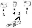
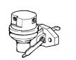
约翰迪尔 6068T/H 6.8T/H 活塞(米)RE527039 排放 2 & 3
|
|
|
发动机和设备型号
|
孔径:
4.19 in 106.5 mm
销径 Ø:
1.6250 in (+/- .0002) = 41mm
发动机型号:
6068HT069
|
|
|
强鹿JOHN DEERE柴油机配件、发动机配件、发电机组:
P124866、P124867、P551130、P777638、P181099、P772579、P827653、P771548、P771548、P827653、P772579、P772580、P829333、P13194、P550388、C125017、C125004、P772579、C085001、C085002、C085003、C085004、ECB105012、C105003、AF1913、AF4539、C105004、RE533026/
强鹿JOHN DEERE柴油机配件、发动机配件、发电机组:
H0000351、ECC105017、C105003、ECC105028、ECC065003、B125003、ECB125011,RE522528、RE519774、RE532628、RE518176、RE507980、RE518503、RE522515、RE504836、RE509031、RE509032、RE59754、RE507284、RE59754、RE519626、RE518977、RE508202、RE58935(20mar01) 02-040-40 powertech? 8.1 l diesel engines — base engine 032001 pn=236 crankshaft, main bearings&flywheel repair&adjustment 02 040 41 rg,rg34710,1151 –19–17may99–1/1 crankshaft rear oil seal&wear sleeve handling precautions rg5640a –un–31oct97 rear oil seal&wear sleeve a—oil seal&wear sleeve use the following precautions for handling seal and wear sleeve: seal (a)&wear sleeve (b) are assembled. do not separate. if parts become separated, discard and replace with a new assembly. attempts to reassemble will cause the wear sleeve to damage the seal allowing engine oil to leak past seal. always install seal&wear sleeve assembly immediately after removal from plastic bag to avoid possible dirt contamination. no lubrication of any kind is to contact seal when installing. use of a lubricant may result in premature seal failure. install oil seal/wear sleeve assembly with the open side of seal&wear sleeve i.d. chamfer toward the engine. if seal is reversed, engine oil may be lost because grooves in oil seal lip would be incorrect with respect to direction of crankshaft rotation. oil seal/wear sleeve assembly must be installed with the jdg476 (85) crankshaft rear oil seal installation tool set. ctm86 (20mar01) 02-040-41 powertech? 8.1 l diesel engines — base engine 032001 pn=237 crankshaft, main bearings&flywheel repair&adjustment 02 040 42 rg,rg34710,1185 –19–23oct97–1/2 install crankshaft rear oil seal&wear sleeve assembly rg4639 –un–05dec97 installing rear oil seal&wear sleeve a—pilot b—allen head cap screws c—oil seal/wear sleeve assembly note: on engines with john deere (funk) rear pto, see ctm67, oem engine acces***ies for procedure to install rear oil seal&wear sleeve. important: do not allow sealant to get on any part of wear sleeve o.d./on oil seal. 1. for separable type seal: apply a light coating of loctite? 680 retaining compound,/equivalent, completely around the leading edge of crankshaft flange. wipe away any sealant that may have gotten on i.d. of seal housing bore. for unitized seal: apply a light coating of clean engine oil around rubber od of seal. 2. install jdg477 (85) pilot (a) on end of crankshaft using the allen head cap screws (b) supplied with tool set. tighten cap screws securely. important: handle seal&wear sleeve assembly carefully. if assembly becomes separated, discard these parts and install a new assembly. when installing the jdg478 driver on jdg477 (85) pilot&crankshaft flange to position oil seal/wear sleeve assembly, locate crossbar of installer at right angle (90°) to allen head cap screws. this allows the crossbar to bottom on pilot, not head of cap screws, assuring correct installation. 3. carefully start oil seal/wear sleeve assembly (c) over jdg477 (85) pilot&crankshaft with open side of seal toward engine. loctite is a registered trademark of loctite corp. ctm86 (20mar01) 02-040-42 powertech? 8.1 l diesel engines — base engine 032001 pn=238 continued on next page crankshaft, main bearings&flywheel repair&adjustment 02 040 43 rg,rg34710,1185 –19–23oct97–2/2 rg4640 –un–05dec97 a—jdg478 driver rear oil seal&wear sleeve installed b—seal&wear sleeve assembly 4. position jdg478 driver (a) so that hole in the cross plate goes over threaded stud of pilot. install washer and nut on stud. 5. tighten nut to draw jdg478 driver in until crossbar bottoms on jdg477 (58) pilot. when the tool bottoms, seal&wear ring assembly (b) will be correctly positioned. 6. remove jdg476 (85) tool set from engine. ctm86 (20mar01) 02-040-43 powertech? 8.1 l diesel engines — base engine 032001 pn=239 crankshaft, main bearings&flywheel repair&adjustment 02 040 44 rg,rg34710,1186 –19–10jun99–1/2 install timing gear cover rg7060 –un–26nov97 thrust washer in timing gear cover rg7050 –un–26nov97 1-6- tightening sequence for cover cap screws a—timing gear cover b—injection pump drive gear cover c—coolant pump cover important: tightening the timing gear cover (a) cap screws one through six in numerical sequence controls the total runout of the crankshaft flange-to-oil seal bore. on engines with auxiliary front drive, tighten those cap screws (group 050) before tightening timing cover screws. 1. lubricate thrust washer (bold arrow) with ty6333 or ty6347 high temperature grease&install in timing gear cover tabs. 2. install a new gasket on engine block. apply a light film of grease to the gasket to hold it in place. 3. install timing gear cover. tighten cap screws one through six to specifications in numerical sequence, as shown. specification timing gear cover-to-cylinder block cap screws—torque 27 n?m (20 lb-ft) 4. install injection pump drive gear cover (b) using a new gasket&tighten cap screws to specifications. specification injection pump gear cover-to-timing gear cover— torque . 27 n?m (20 lb-ft) 5. install coolant pump cover (c) using a new gasket. tighten cap screws to specifications. coolant pump cover-to-timing gear cover—specification 5/16-in. cap screws—torque . 27 n?m (20 lb-ft) 3/8-in. cap screws—torque . 47 n?m (35 lb-ft) 6. trim timing gear cover gasket flush with oil pan gasket rail. 7. install front auxiliary drive assembly using a new idler bushing. seeremove, inspect&install crankshaft gear-driven auxiliary drive in group 050. ctm86 (20mar01) 02-040-44 powertech? 8.1 l diesel engines — base engine 032001 pn=240 continued on next page crankshaft, main bearings&flywheel repair&adjustment 02 040 45 rg,rg34710,1186 –19–10jun99–2/2 8. using a new o-ring, install magnetic speed sen*** in timing gear cover, if removed. 9. install crankshaft front wear sleeve&oil seal. see install crankshaft front oil seal later in this group. rg,rg34710,1187 –19–23oct97–1/1 install front wear sleeve rg6476 –un–05dec97 tool for installing front wear sleeve rg6477 –un–05dec97 installing front wear sleeve note: front wear sleeve can be installed with timing gear cover removed/installed. 1. coat i.d. of new wear sleeve with loctite? 680 retaining compound/equivalent. position wear sleeve on crankshaft flange. 2. use the jdg467 driver (from jde3 installer set), along with large washer&cap screw that secures damper to crankshaft. tighten cap screw until driver bottoms. 3. remove installation tools. clean any sealant from o.d. of wear sleeve&i.d. of seal bore. loctite is a registered trademark of loctite corp. ctm86 (20mar01) 02-040-45 powertech? 8.1 l diesel engines — base engine 032001 pn=241 crankshaft, main bearings&flywheel repair&adjustment 02 040 46 rg,rg34710,1188 –19–23oct97–1/1 install crankshaft front oil seal rg6479 –un–05dec97 protector for installing front oil seal rg6480 –un–05dec97 installing front oil seal a—jdg720-2 seal protector important: whenever front oil seal is replaced, the wear sleeve must also be replaced. 1. place jdg720-2 seal protector (a) on nose of crankshaft. lubricate i.d. of front oil seal lips with clean engine oil. slide seal with spring side of seal facing engine onto seal protector. be careful not to roll oil seal lips. 2. place jdg720-5 seal installer onto seal protector against seal. do not use spacer ring provided with tool set. 3. with nut&washer installed onto jdg720-1 forcing screw, thread forcing screw into nose of crankshaft until it bottoms. 4. tighten nut against crossplate of installer until installer bottoms onto front face of timing gear cover. 5. remove installation tools. verify seal is installed square in bore&that seal lips are not rolled on wear sleeve. oil seal should be installed to following specification. specification front oil seal installed below front lip of seal bore—recess 8.9 mm (0.35 in.) ctm86 (20mar01) 02-040-46 powertech? 8.1 l diesel engines — base engine 032001 pn=242 crankshaft, main bearings&flywheel repair&adjustment 02 040 47 rg,rg34710,1189 –19–03jan01–1/1 install vibration damper rg5882 –un–26nov97 installing vibration damper a—cap screw b—damper note: on engines with dual dampers, always replace both双鸭山JohnDeere强鹿凸轮随动件一级代理,黔西南JohnDeere机油冷却器RE59296市场报价,桂林约翰迪尔发动机柴油格座厂家供货,龙岩约翰迪尔强鹿re533910采棉机机油滤芯信息,延边强鹿柴油发动机3029衬垫套代理商,白城美国强鹿JOHNDEERE(约翰迪尔)柴油机高压油泵诚信推荐,承德约翰迪尔发动机配件的价格,运城强鹿6068柴油机连杆铜套厂家供货,凉山强鹿油泵RE66153诚信推荐,克孜勒苏约翰迪尔强鹿4045发动机内部修理套件哪家好,郴州约翰迪尔AT21132止推轴承厂家批发,防城港强鹿JohndeerePE4045缸套多少钱,鄂尔多斯强鹿滤芯滤清器RE51629价格,南京强鹿柴油发动机空气滤F040A6信息,嘉义约翰迪尔装载机发动机启动马达哪家好,大同JohnDeere机油泵RE543187供货商,海北JohnDeere曲轴位置传感器TRA519144多少钱,丽江约翰迪尔6090柴油机挺铜柱代理,巴音郭楞强鹿6090柴油发动机皮带张紧轮信息, dampers as a matched set. important: the vibration damper assembly is not repairable&should be replaced every 4500 hours/60 months, whichever occurs first. 1. install crankshaft woodruff key with tab facing toward front of engine&key firmly seated in keyway. position damper (b) onto crankshaft. important: always use new cap screws when installing damper to crankshaft&fan pulley to damper. 2. use hardened washer (part of damper assembly) and insert a cap screw that is 25 mm (1 in.) longer than original cap screw (a). tighten cap screw until it just bottoms out. 3. remove cap screw&install original cap screw with same hardened washer. 4. tighten cap screw to specifications. specification vibration damper-to-crankshaft cap screws—torque 230 n?m (170 lb-ft) 5. install crankshaft pulley (if equipped) to damper. tighten cap screws to specifications. specification crankshaft pulley-to-damper cap screws (single dampers for gen-set applications)—torque . 61 n?m (45 lb-ft) crankshaft pulley-to-damper cap screws (all other applications)— torque . 70 n?m (52 lb-ft) note: on later engines, damper&pulley are a one-piece unit. ctm86 (20mar01) 02-040-47 powertech? 8.1 l diesel engines — base engine 032001 pn=243 crankshaft, main bearings&flywheel repair&adjustment 02 040 48 rg,rg34710,1190 –19–03jan01–1/1 install sae 2&3 flywheel housing rg10214 –un–23jun99 installing sae 3 flywheel housing a—flywheel housing on sae 1&all aluminum flywheel housings, the flywheel housing is installed after the flywheel. caution: flywheel housing (a) is heavy. plan a handling procedure to avoid personal injuries. note: engines not requiring a gasket are usually dry clutch applications&are metal to metal connection. 1. on engines requiring a gasket between block and flywheel housing, inspect cylinder block&flywheel housing gasket surfaces to see that they are clean. scrape off all old gasket material. install a new gasket without sealant between block&flywheel housing. 2. install flywheel housing on cylinder block. note: use new cap screws when installing flywheel housing. 3. dip threads of cap screw in engine oil before installing. install&tighten cap screws to specifications. specification sae 2&3 flywheel housing-to-cylinder block cap screws—torque 365 n?m (269 lb-ft) sae 3 flywheel housing-to-oil pan 1/2 in. cap screws—torque . 129 n?m (95 lb-ft) sae 3 flywheel housing-to-oil pan 3/8 in. cap screws—torque . 47 n?m (35 lb-ft) sae 2 flywheel housing-to-cylinder block 3/4-in. cap screws (with rear pto)— torque . 325 n?m (240 lb-ft) sae 2 flywheel housing-to-cylinder block 5/8-in. cap screws (with rear pto)— torque . 275 n?m (203 lb-ft) ctm86 (20mar01) 02-040-48 powertech? 8.1 l diesel engines — base engine 032001 pn=244 crankshaft, main bearings&flywheel repair&adjustment 02 040 49 rg,rg34710,1191 –19–10jun99–1/1 install flywheel rg10213 –un–23jun99 installing flywheel a—locations for guide studs two guide studs may be used at cap screw locations (a) opposite each other to aid in flywheel installation. caution: flywheel is heavy. plan a handling procedure to avoid personal injuries. note: always use new cap screws when installing flywheel. do not use plated cap screws. important: flywheel must be clean&free of oil before installing. clean threaded holes in crankshaft carefully. do not blow them out with compressed air. these are through holes&debris could be blown into the engine crankcase. 1. on engines without rear pto, coat threads of flywheel attaching cap screws with loctite? 242 or its equivalent. 2. position flywheel over dowel pin&install drive hub (if equipped). start four cap screws. remove guide studs&install remaining cap screws. 3. install remaining flywheel attaching cap screws. 4. tighten flywheel attaching cap screws to specifications. specification drive hub-to-flywheel cap screws—torque 115 n?m (85 lb-ft) flywheel-to-crankshaft cap screws (with rear pto)— torque 162 n?m (120 b-ft) flywheel-to-crankshaft cap screws (all other applications)— torque . 115 n?m (85 lb-ft) loctite is a registered trademark of loctite corp. ctm86 (20mar01) 02-040-49 powertech? 8.1 l diesel engines — base engine 032001 pn=245 crankshaft, main bearings&flywheel repair&adjustment 02 040 50 rg,rg34710,1192 –19–10jun99–1/1 install sae 1 flywheel housing caution: flywheel housing is heavy. plan a handling procedure to avoid personal injuries. on sae 2&3 cast-iron flywheel housings, the housing must be installed before installing flywheel. 1. scrape off all old gasket material. install a new gasket without sealant between block&flywheel housing. 2. install flywheel housing on cylinder block. note: always use new cap screws when installing flywheel housing. 3. dip threads of cap screw in engine oil before installing. install&tighten cap screws to specifications. specification sae 1 flywheel housing-to-cylinder block cap screws—torque . 365 n?m (269 lb-ft) rg,rg34710,1193 –19–23oct97–1/1 complete final assembly 1. install oil pump assembly&oil pan (group 20). fill engine with clean engine oil. 2. fill cooling system with proper coolant after engine installation&perform engine break-in. see perform engine break-in serial number ( — 199,999) at end of group 020,/see perform engine break-in serial number (200,000— ) at end of group 021. ctm86 (20mar01) 02-040-50 powertech? 8.1 l diesel engines — base engine 032001 pn=246 group 050 camshaft&timing gear train repair&adjustment 02 050 1 rg,rg34710,1199 –19–23oct97–1/1 check camshaft end play&measure gear backlash rg7211 –un–28jul94 measuring camshaft end play note: camshaft end play must be measured before removing timing gear cover, as thrust washer in back side of timing gear cover limits camshaft end play. 1. remove injection pump drive gear cover (shown removed). 2. install magnetic base dial indicator on front face of cylinder block&position dial indicator tip on front face of camshaft gear, as shown. set dial indicator to zero. 3. move camshaft gear back&forth&observe end play reading. compare reading with specification given below. specification camshaft—end play 0.013—0.500 mm (0.0005—0.0200 in.) new . wear limit 0.65 mm (0.0260 in.) maximum allowable if end play is excessive, remove timing gear cover and crankshaft&measure thickness of thrust washers. 4. position indicator plunger tip against camshaft gear tooth with a preload. 5. measure backlash between camshaft drive gear and crankshaft gear in three (3) different positions around the camshaft gear. compare readings with specifications given below. specification camshaft drive gear-to-crankshaft gear— backlash . 0.076 mm (0.003 in.) min. replace gear if backlash does not equal/exceed specification. ctm86 (20mar01) 02-050-1 powertech? 8.1 l diesel engines — base engine 032001 pn=247 camshaft&timing gear train repair&adjustment 02 050 2 rg,rg34710,1200 –19–08jun99–1/2 remove vibration damper&timing gear cover rg7209 –un–26nov97 removing crankshaft vibration damper rg7210a –un–08feb01 removing timing gear cover a—jdg721 hub puller b—coolant pump cover c—injection pump drive gear cover d—speed sen*** wiring connector for timing cover removal procedure with engine installed in vehicle (8000 tractors), refer to remove and install timing gear cover—engine installed in vehicle, in group 040. 1. drain oil (if not previously done),&remove oil pan. remove oil pump if crankshaft is to be removed. see remove engine oil pump in group 060. 2. remove cap screw&washer on damper pulley. install jdg787 thread protector in nose of crankshaft. important: do not use a jaw-type puller to remove vibration damper. damage could result to the damper. never apply thrust on outer ring of damper. do not drop damper/strike with a hammer. 3. remove damper from crankshaft using jdg721 hub puller (a). note: d01207aa (otc518) puller set (not shown) may also be used to remove damper. http://www.rxdlkj.com/m/peijianproducts.asp?pid=2914. disconnect speed sen*** wiring connector (d) (shown disconnected),&remove injection pump drive gear cover (c). 5. check camshaft end play. see check camshaft end play&measure gear backlash earlier in this group. important: whenever timing gear cover is removed, always install a new front oil seal&wear sleeve. 6. remove coolant pump cover (b). 7. if equipped, remove crankshaft gear-driven auxiliary drive. see remove, inspect&install crankshaft gear-driven auxiliary drive later in this group. ctm86 (20mar01) 02-050-2 powertech? 8.1 l diesel engines — base engine 032001 pn=248 continued on next page camshaft&timing gear train repair&adjustment 02 050 3 rg,rg34710,1200 –19–08jun99–2/2 8. remove all remaining cap screws&remove timing gear cover. 9. remove front oil seal from timing gear cover. install a new seal after timing gear cover is installed. see install crankshaft front oil seal in group 040. 10. remove crankshaft front wear sleeve. see remove crankshaft front oil seal&wear sleeve in group 040. dpsg,ouo1004,911 –19–10jun99–1/7 remove, inspect,&install crankshaft gear-driven auxiliary drive—if equipped rg10055 –un–23jun99 button head cap screw rg10056 –un–23jun99 auxiliary drive idler bushing/spacer a—timing gear cover cap screws b—idler housing cap screws c—button head cap screw d—d01209aa puller e—idler gear bushing/spacer note: various auxiliary drive options are available; removal&installation of all options are similar. the auxiliary drive is integrated into the engine front timing gear cover. refer to ctm67-oem engine acces***ies for removal of auxiliary drive acces***ies&repair of auxiliary drive components. 1. if equipped, remove auxiliary drive acces***y (air compres***, hydraulic pump, etc.) (shown removed). 2. remove vibration damper (shown removed). 3. loosen idler housing cap screws (b)&timing gear cover cap screws (a). 4. remove button head cap screw (c). 5. remove idler gear bushing/spacer (e) from timing gear cover using d01209aa slide hammer&attachment (d)&discard bushing/spacer. ctm86 (20mar01) 02-050-3 powertech? 8.1 l diesel engines — base engine 032001 pn=249 continued on next page camshaft&timing gear train repair&adjustment 02 050 4 dpsg,ouo1004,911 –19–10jun99–2/7 rg10057 –un–23jun99 remove auxiliary drive assembly a—timing gear cover-to-cylinder block cap screw b—idler housing-to-timing gear cover cap screws c—idler housing-to-cylinder block cap screws 6. remove cap screws (a—c)&remove idler housing and gear. 7. remove idler housing-to-timing gear housing face seal and o-ring. face seal may be reused if not damaged. 8. clean&inspect auxiliary drive assembly for cracked housing, worn/damaged bearings&damaged gear/spline. replace components as required. dpsg,ouo1004,911 –19–10jun99–3/7 rg6904 –un–05dec97 idler gear a—cap screw b—housing bore 9. grease&install o-ring in housing bore (b). note: inner idler bearing support has one threaded hole, and is installed toward block side of housing. 10. if removed, install idler gear into idler housing. install cap screw with seal (a) to hold idler gear in place. continued on next page ctm86 (20mar01) 02-050-4 powertech? 8.1 l diesel engines — base engine 032001 pn=250 camshaft&timing gear train repair&adjustment 02 050 5 dpsg,ouo1004,911 –19–10jun99–4/7 rg6903 –un–05dec97 o-ring groove a—o-ring groove 11. insert idler shaft through idler housing&idler gear until flush with block side of housing. important: white dot on one end of shaft must face out toward front of engine. 12. grease o-ring groove (a) in back side of idler housing. insert o-ring. dpsg,ouo1004,911 –19–10jun99–5/7 rg10059 –un–23jun99 button head cap screw a—button head cap screw b—large o-ring c—small o-ring d—idler bushing/spacer note: face seal may be reused if it is not cut, nicked, or damaged. 13. using a short guide stud, place face seal on timing gear cover opening. gauge hole in seal must be positioned toward bottom of opening. important: be careful not to damage face seal or displace o-ring on back side of idler housing during assembly. 14. carefully insert idler gear into opening of timing gear cover until idler gear meshes with crankshaft gear, and housing is seated against face seal. push idler bushing/spacer (d) into block. 15. check condition of o-rings (b)&(c) on large button head cap screw (a). grease o-rings&install cap screw through idler shaft. thread into block until finger tight. continued on next page ctm86 (20mar01) 02-050-5 powertech? 8.1 l diesel engines — base engine 032001 pn=251 camshaft&timing gear train repair&adjustment 02 050 6 dpsg,ouo1004,911 –19–10jun99–6/7 rg10236 –un–30jun99 install auxiliary drive assembly a—idler housing-to-timing gear cover cap screws b—idler housing-to-cylinder block cap screw c—idler housing d—idler housing-to-cylinder block cap screw e—timing gear cover-to-cylinder block cap screws f—idler bushing button head cap screw g—idler housing-to-idler bearing cap screw note: center timing gear cover-to-cylinder block cap screw must have a seal. 16. remove guide stud. install timing gear cover cap screws (e), idler housing cap screws (a&b) and cap screw (d) finger tight. 17. tighten cap screws to specifications in the following sequence: ? idler housing-to-timing gear cover (a): specification auxiliary drive idler housing-to-timing gear cover (3/8 in.)—torque . 41 n?m (30 lb-ft) ? idler housing-to-cylinder block (b) 3/8 inch cap screws: specification auxiliary drive idler housing-to-cylinder block (3/8 in.)—torque . 41 n?m (30 lb-ft) ? idler housing-to-cylinder block (d) 1/2 inch cap screws: specification auxiliary drive idler housing-to-cylinder block (1/2 in.)—torque . 127 n?m (94 lb-ft) ? idler bushing/spacer button head cap screw (f): specification auxiliary drive idler shaft button head cap screw—torque 150 n?m (110 lb-ft) continued on next page ctm86 (20mar01) 02-050-6 powertech? 8.1 l diesel engines — base engine 032001 pn=252 camshaft&timing gear train repair&adjustment 02 050 7 dpsg,ouo1004,911 –19–10jun99–7/7 ? timing gear cover-to-cylinder block (e): specification timing gear cover-to-cylinder block cap screws (5/16 in.)— torque . 27 n?m (20 lb-ft) ? idler housing-to-idler bearing (g): specification auxiliary drive idler housing-to-idler bearing (5/16 in.)—torque . 27 n?m (20 lb-ft) 18. check idler gear-to-crankshaft gear backlash. backlash must be as follows: specification auxiliary drive idler gear-to-crankshaft gear— backlash 0.11—0.7 mm (0.004—0.028 in.) . 19. install vibration damper. ctm86 (20mar01) 02-050-7防城港强鹿JohndeerePE4045缸套厂家批发,金昌强鹿6081柴油发动机前油封公司,三明约翰迪尔传感器RE522823信息,舟山JohnDeere凸轮轴衬套RE504914信息,遂宁约翰迪尔3029DF120水泵价格行情,宁波约翰迪尔装载机发动机出油阀哪家买,海西约翰迪尔传感器RE519144多少钱,松原约翰迪尔发动机连杆铜套哪家买,澳门离岛约翰迪尔柴油机连杆衬套TR114082哪里买,南阳强鹿气门弹簧R91822代理商,西宁强鹿柴油发动机活塞销诚信推荐,金华约翰迪尔活塞环RE503528哪里买,泰安约翰迪尔CH530甘蔗收获机发动机配件一级代理,泸州约翰迪尔强鹿RE171235RE171236P780522空气滤芯批发,铁岭强鹿柴油机泵芯哪家买,阿勒泰约翰迪尔加大主轴瓦RE534181批发商,新乡johndeere约翰迪尔强鹿柴油发动机气缸盖信息, powertech? 8.1 l diesel engines — base engine 032001 pn=253 camshaft&timing gear train repair&adjustment 02 050 8 rg,rg34710,1202 –19–23oct97–1/3 remove camshaft rg6614 –un–05dec97 timing marks—camshaft&crankshaft gears a—timing marks note: it is not necessary to remove cylinder head from engine for camshaft removal. if push rods are bent/show excessive scuffing, it may be necessary to remove cylinder head for inspection of block, head, cam lobes&cam followers. 1. drain engine oil&coolant, if not previously done. remove timing gear cover as detailed earlier in this group. see remove vibration damper and timing gear cover in this group. 2. rotate engine flywheel with jde81-1/jdg820 flywheel rotation tool&lock engine at no. 1 cylinder’s “tdc-compression” stroke with jde81-4 timing pin. timing marks (a) on camshaft gear and crankshaft gear should be aligned. if timing marks are not aligned, remove timing pin and continue to rotate engine until marks align. timing pin should enter hole in flywheel. engine will be locked at no. 1 “tdc-compression” stroke. 3. remove rocker arm assembly&push rods. see remove cylinder head serial number ( — 199,999) in group 020,/see remove cylinder head serial number (200,000— ) in group 021. 4. when removing camshaft with engine on rollover stand, roll engine to a position where followers fall away from camshaft lobes (oil pan side up)/hold cam followers away from lobes with d15001nu magnetic holding set. continued on next page ctm86 (20mar01) 02-050-8 powertech? 8.1 l diesel engines — base engine 032001 KEY PART NO. PART NAME QTY SERIAL NO. F F F REMARKS
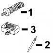
1 .. HOLDER NA X
2 T24210 O-RING 6 X
3 R76358 O-RING 1 X
4 14M7272 NUT 3 X M6
5 12M7006 LOCK WASHER 3 X 0.236"
6 R67879 GASKET 1 X
7 R53899 WASHER 1 X
8 AR77114 CONTROL VALVE 1 X
9 R53901 WASHER 1 X
10 R63016 ADAPTER 1 X
11 R67364 ELBOW FITTING 1 -087549 X
RE502650 FITTING 1 087550- X
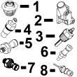
KEY PART NO. PART NAME QTY SERIAL NO. F F F REMARKS
1 RE10582 CONTROL VALVE 1 X
2 R64857 WASHER 1 X
3 R77536 JAW 3 X
4 .. HOLDER NA X
5 R73821 O-RING 6 X
6 R73820 SHIM 6 X
7 R73864 O-RING 1 X
8 R64926 LOCK WASHER 3 X
9 14M7272 NUT 3 X
10 R64927 O-RING 1 X
11 R78774 GASKET 1 X
12 R78773 PACKING 2 X