配件详情
约翰迪尔 4045 4.5T/H 活塞(米) RE515037 排放 2 & 3
|
|
|
发动机和设备型号
|
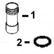
孔径:
4.19 in 106.5 mm
销径 Ø:
1.6250 in (+/- .0002) = 41mm
|
|
|
供应美国约翰.迪尔(强鹿)JOHNDEERE纯正配件。P550758、P550020、P550595、P558329、P550351、P551421、P551423、P556745、P551428、P551422、P551435、P551434、P550192、P550397、P551352、P181054、P77868、P777869、P550667、P550779/
强鹿JOHN DEERE柴油机配件、发动机配件、发电机组:
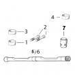
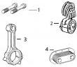
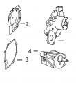
P551345、P608667、P607557、P611856、P611857、P124866、P124867、P551130、P777638、P181099、P772579、P827653、P771548、P771548、P827653、P772579、P772580、P829333、P13194、P550388、C125017、C125004、P772579、C085001、C085002checklist&continue the inspection. continued on next page ctm86 (20mar01) 02-080-6 powertech? 8.1 l diesel engines — base engine 032001 pn=320 air intake&exhaust system repair&adjustment 02 080 7 rg,rg34710,1259 –19–23oct97–3/12 rg4524 –un–05dec97 checking compres*** inlet note: you will need a good light source for this check. 3. check compres*** inlet for wheel rub on the housing (arrow). look very closely for any score marks on the housing itself&check the tips of the compres*** wheel blades for damage. rg,rg34710,1259 –19–23oct97–4/12 rg4525 –un–05dec97 checking compres*** outlet a—compres*** housing outlet compres*** housing outlet 1. check compres*** housing outlet (a). the outlet should be clean&free of dirt/oil. 2. mark it on your checklist if dirt/oil is found and continue the inspection. continued on next page ctm86 (20mar01) 02-080-7 powertech? 8.1 l diesel engines — base engine 032001 pn=321 air intake&exhaust system repair&adjustment 02 080 8 rg,rg34710,1259 –19–23oct97–5/12 rg4526 –un–05dec97 checking turbine housing inlet ports turbine housing inlet check the turbine housing inlet ports (arrow) for oil in housing, excessive carbon deposit/erosion of center walls. note: if the inlet is wet with oil,/has excessive carbon deposits, an engine problem is likely. center wall erosion (cracking/missing pieces), indicate excessive exhaust temperature. rg,rg34710,1259 –19–23oct97–6/12 rg4527 –un–05dec97 checking turbine wheel&outlet a—turbine housing outlet b—blades turbine housing outlet&turbine wheel 1. use a flashlight to look up inside the turbine housing outlet (a)&check blades (b) for foreign object damage. continued on next page ctm86 (20mar01) 02-080-8 powertech? 8.1 l diesel engines — base engine 032001 pn=322 air intake&exhaust system repair&adjustment 02 080 9 rg,rg34710,1259 –19–23oct97–7/12 rg4528 –un–05dec97 checking turbine wheel blades 2. inspect the wheel blades&housing for evidence of wheel rub (arrow). wheel rub can bend the tips of the blades with the housing showing wear/damage. rg,rg34710,1259 –19–23oct97–8/12 rg4532 –un–05dec97 checking shaft rotation&clearance 3. rotate the shaft, using both hands, to check rotation and clearance. the shaft should turn freely, however, there may be a slight amount of drag. continued on next page ctm86 (20mar01) 02-080-9 powertech? 8.1 l diesel engines — base engine 032001 pn=323 air intake&exhaust system repair&adjustment 02 080 10 rg,rg34710,1259 –19–23oct97–9/12 rg4533 –un–05dec97 checking for contact of compres***&turbine wheels important: use only moderate hand force (3-4 pounds) on each end of shaft. 4. next, pull up on the compres*** end of the shaft and press down on the turbine end while rotating shaft. neither the compres*** wheel nor the turbine wheel should contact the housing at any point. note: there will be some “play” because the bearings inside the center housing are free floating. rg,rg34710,1259 –19–23oct97–10/12 rg4529 –un–05dec97 checking center housing external center housing&joints visually check the outside of the center housing, all connections to the compres***,&turbine housing for oil. note: if oil is present, make sure it is not coming from a leak at the oil supply/return line. important: before you finalize your conclusion that the turbocharger has not failed, it is strongly recommended that the following procedures of checking radial bearing clearance&axial bearing endplay with a dial indicator be performed. these procedures are not required if a failure mode has already been identified. continued on next page ctm86 (20mar01) 02-080-10 powertech? 8.1 l diesel engines — base engine 032001 pn=324 air intake&exhaust system repair&adjustment 02 080 11 rg,rg34710,1259 –19–23oct97–11/12 rg11675 –un–01feb01 checking axial bearing end play perform axial bearing end play test this test will give an indication of the condition of the thrust bearing within the center housing&rotating assembly. 1. mount magnetic base dial indicator (black arrow) so that indicator tip rests on flat surface on turbine end of shaft. preload indicator tip&zero dial on indicator. 2. move shaft axially back&forth by hand. 3. observe&record total dial indicator movement. specification turbocharger shaft—axial bearing end play 0.064—0.114 mm (0.0025—0.0045 in.) if bearing end play is not within specification, install a replacement turbocharger. rg,rg34710,1259 –19–23oct97–12/12 rg4534 –un–05dec97 checking shaft end play 4. next, check shaft endplay by moving the shaft back and forth (white arrows) while rotating. there will be some endplay but not to the extent that the wheels contact the housings. note: these diagnostic procedures will allow you to determine the condition of the turbocharger. if the turbocharger has failed, analysis of your inspection notes should direct you to the specific areas of the engine to correct the problems causing the turbocharger failure see turbocharger failure analysis outlined earlier in this group. it is not unusual to find that a turbocharger has not failed. if your turbocharger passes all the inspections, the problem lies somewhere else. ctm86 (20mar01) 02-080-11 powertech? 8.1 l diesel engines — base engine 032001 pn=325 air intake&exhaust system repair&adjustment 02 080 12 rg,30,jw7571 –19–20nov97–1/1 repair turbocharger turbochargers used on the engines covered in this manual are available through service parts as a complete remanufactured assembly only. individual components for repair are not available. rg,rg34710,1266 –19–23oct97–1/1 prelube turbocharger rg5858 –un–13aug91 prelubing turbocharger important: do not spin the rotor assembly with compressed air. damage to bearings can occur when using compressed air. fill oil return (drain) port with clean engine oil&spin rotating assembly by hand to properly lubricate bearings. if turbocharger is to be stored for an extended period of time, lubricate internally&install protective covers on all openings. ctm86 (20mar01) 02-080-12 powertech? 8.1 l diesel engines — base engine 032001 pn=326 air intake&exhaust system repair&adjustment 02 080 13 rg,rg34710,1268 –19–28apr99–1/2 install turbocharger rg7004 –un–26nov97 installing turbocharger a—oil line b—oil return tube important: if turbocharger failed because of foreign material entering the air intake system, be sure to examine the system and clean as required to prevent a repeat failure. on 6081a engines, visually inspect the aftercooler&clean if necessary. oil may have accumulated from the failed turbo. if not previously done, prime (prelube) turbocharger rotating assembly prior to installing turbocharger on engine. prelube center housing with clean engine oil through oil return (drain) hole as shown. turn rotating assembly by hand to lubricate bearings. note: two threaded guide studs may be used to hold turbocharger-to-exhaust manifold gasket in place and aid in turbocharger installation. 1. put a new gasket on turbocharger-to-exhaust manifold mounting surface (not shown). 2. position turbocharger against gasket on exhaust manifold. 3. apply pt569 never-seez? compound to all turbocharger mounting cap screws. install cap screws and tighten to specifications. specification turbocharger-to-exhaust manifold nuts (marine only)—torque . 40 n?m (30 lb-ft) turbocharger-to-exhaust manifold cap screws—torque 24 n?m (18 lb-ft) note: remove all caps/plugs from turbocharger openings. 4. install turbocharger oil return (drain) tube (b) using a new gasket. tighten cap screws to specifications. never-seez is a registered trademark of emhart chemical group. ctm86 (20mar01) 02-080-13 powertech? 8.1 l diesel engines — base engine 032001 pn=327 continued on next page air intake&exhaust system repair&adjustment 02 080 14 rg,rg34710,1268 –19–28apr99–2/2 specification turbocharger oil return line— torque . 34 n?m (25 lb-ft) 5. connect oil line (a) to elbow adapter&tighten securely. 6. if equipped, connect wastegate diaphragm hose. (if replacing hose, cut to length from roll furnished by parts.) 7. connect air intake&exhaust piping to turbocharger. tighten all connections securely. (for vehicle engines, refer to machine technical manual.) important: before starting an engine with a new/repaired turbocharger, crank the engine over (but do not start) for several seconds to allow engine oil to reach turbocharger bearings. do not crank engine longer than 30 seconds at a time to avoid damaging starting motor. 8. start&run engine at low idle while checking oil inlet and air piping connections for leaks. ctm86 (20mar01) 02-080-14 powertech? 8.1 l diesel engines — base engine 032001 pn=328 air intake&exhaust system repair&adjustment 02 080 15 dpsg,ouo1004,815 –19–28apr99–1/2 remove, inspect,&install exhaust manifold rg7005 –un–26nov97 removing exhaust manifold rg7006 –un–26nov97 sealing ring for front-to-rear exhaust manifolds a—turbocharger b—rear exhaust manifold c—front exhaust manifold d—sealing ring 1. remove turbocharger (a) from exhaust manifold. see remove turbocharger earlier in this group. 2. remove cap screws&remove rear exhaust manifold (b)&front exhaust manifold (c). remove manifold gaskets&discard. 3. remove&discard front-to-rear exhaust manifold sealing ring (d). 4. remove all residue&gasket material from gasket surfaces. 5. thoroughly clean passages in exhaust manifold and exhaust below. 6. inspect each exhaust manifold for cracks/damage. inspect machined mounting surfaces for burrs/other defects which might prevent gaskets from sealing properly. replace parts as needed. 7. to install exhaust manifold, reverse removal procedure and use new gaskets. note: it is not necessary to use an anti-seize compound on stainless steel exhaust manifold cap screws. the special 12-point flange head cap screws used on 8000 series tractors have pre-applied anti-sieze compound. 8. on 8000 series tractors using special 12-point flange head cap screws, apply pt569 never-seez? compound, only to cap screws being reused. tighten exhaust manifold mounting cap screws to specifications. never-seez is a registered trademark of emhart chemical group continued on next page ctm86 (20mar01) 02-080-15 powertech? 8.1 l diesel engines — base engine 032001 pn=329 air intake&exhaust system repair&adjustment 02 080 16 dpsg,ouo1004,815 –19–28apr99–2/2 specification exhaust manifold-to-cylinder head cap screws (6081hrw engines)—torque 80 n?m (60 lb-ft) exhaust manifold-to-cylinder head cap screws (all other engines)—torque 47 n?m (35 lb-ft) ctm86 (20mar01) 02-080-16 powertech? 8.1 l diesel engines — base engine 032001 pn=330 air intake&exhaust system repair&adjustment 02 080 17 rg,rg34710,1270 –19–23oct97–1/1 remove, inspect,&install intake manifold (6081t&6081h engines) rg7007 –un–26nov97 removing intake manifold a—intake manifold important: all intake manifold connections at the turbocharger&engine cylinder head must be tight to prevent loss of power resulting from lack of intake manifold pressure. intake manifold hose&cap screw connections should be inspected periodically for tightness. whenever a tune-up has been performed on the engine,/whenever it is suspected that the horsepower output might be low, the intake manifold pressure (turbo-boost) should be checked. see measure intake manifold pressure in group 150. 1. remove exhaust manifold, shown removed. see remove, inspect&install exhaust manifold earlier in this group. 2. remove air intake connections from intake manifold (a) as detailed in machine technical manual. 3. disconnect air heater wire from manifold, if equipped. 4. remove six cap screws&remove intake manifold from cylinder head. remove&discard manifold gaskets. 5. inspect the intake manifold for serviceability. replace if it is cracked/otherwise damaged. 6. inspect the machined mating surfaces of cylinder head&intake manifold. clean, as required, by using a scraper and/or wire brush,&compressed air. 7. to install intake manifold, reverse removal procedures&use new gaskets. 8. tighten intake manifold cap screws to specifications. specification intake manifold-to-cylinder head—torque 47 n?m (35 lb-ft) 9. install exhaust manifold assembly&turbocharger as detailed earlier in this group. 10. connect all air intake&exhaust piping. (for vehicle engines, refer to machine technical manual.) ctm86 (20mar01) 02-080-17 powertech? 8.1 l diesel engines — base engine 032001 pn=331 air intake&exhaust system repair&adjustment 02 080 18 rg,rg34710,1271 –19–23oct97–1/3 remove vertically-mounted aftercooler and intake manifold (6081a engines) rg8762 –un–02dec97 removing aftercooler&intake manifold a—clamps b—turbocharger c—aneroid-to-intake manifold connector d—air intake cover cap screws caution: explosive release of fluids from pressurized cooling system can cause serious burns. wait until engine coolant is cool enough to touch with bare hands before draining. slowly loosen radiator cap to first stop to relieve pressure. 1. open coolant pump&block drain valves to completely drain engine coolant. 2. thoroughly clean exterior of turbocharger (b), intake manifold&adjacent areas to prevent entry of dirt into the engine when parts are removed. 3. remove turbocharger as described earlier in this group. 4. loosen clamps (a) on inlet&outlet hose. remove coolant hoses from aftercooler. 5. remove aneroid-to-intake manifold connector (c), if equipped. 6. remove air intake cover cap screws (d). rg,rg34710,1271 –19–23oct97–2/3 rg8764 –un–02dec97 removing aftercooler a—air intake cover b—aftercooler c—intake manifold d—gaskets e—aftercooler end seal 7. carefully lift air intake cover (a) from intake manifold (c). 8. remove aftercooler (b). 9. remove&discard gasket (d). 10. inspect aftercooler end seal (e)&replace as needed. ctm86 (20mar01) 02-080-18 powertech? 8.1 l diesel engines — base engine 032001 pn=332 continued on next page air intake&exhaust system repair&adjustment 02 080 19 rg,rg34710,1271 –19–23oct97–3/3 rg8767 –un–02dec97 removing intake manifold 11. remove the six intake manifold-to-cylinder head caps screws (a)&remove intake manifold. remove and discard all manifold gaskets. 12. inspect&repair aftercooler. see inspect and repair aftercooler (6081a engines), later in this group. rg,rg34710,1272 –19–23oct97–1/2 remove&disassemble horizontally-mounted aftercooler (6081a engines) rg8763 –un–02dec97 removing杭州约翰迪尔联合收割机发动机止推片哪里买,扬州迪尔柴油机大修包批发商,抚顺johndeere约翰迪尔强鹿柴油机节温器哪家买,基隆johndeere约翰迪尔强鹿柴油发动机启动马达RE515895找哪家,三沙约翰迪尔6068柴油机机油冷却器价格,澳门离岛强鹿柴油机水泵价格,绍兴强鹿6090柴油机加大止推轴承瓦价格行情,阿拉善约翰迪尔发动机涡轮增压器公司,高雄约翰迪尔发动机曲轴瓦多少钱,海西约翰迪尔柴油机排气门导管R119132哪里买,信阳约翰迪尔6068柴油机气门油封公司,甘南强鹿柴油机发动机修理包RE527549价格,黄山约翰迪尔发动机喷油咀厂家供货,黑河约翰迪尔柴油机T20034凸轮轴下衬套厂家供应,延安johndeere约翰迪尔强鹿柴油机滤清器价格,许昌强鹿柴油发电机组连杆的价格,山南强鹿气缸盖螺丝R502511批发价,平凉johndeere约翰迪尔强鹿柴油机缸体价格,娄底强鹿柴油机喷油嘴哪家好,河池强鹿柴油机凸轮轴瓦厂家价格,德宏强鹿滤芯市场报价,大连强鹿柴油发电机组飞轮壳哪里买,淄博约翰迪尔6068柴油机温度传感器代理,三亚johndeere约翰迪尔强鹿柴油机机油冷却器代理,阜新JohnDeere柴油机小修包IK6090市场报价, aftercooler a—turbocharger oil inlet line b—turbocharger oil return line c—coolant inlet&outlet hoses d—intake manifold cap screws 1. completely drain engine coolant from aftercooler. 2. disconnect turbocharger oil inlet line (a)&return line (b). 3. remove four turbocharger-to-exhaust manifold cap screws. 4. remove coolant inlet&outlet hoses (c) from aftercooler. 5. remove top three intake manifold cap screws (d). install guide studs at the three locations. remove remaining cap screws. 6. remove intake manifold&aftercooler as an assembly. 7. remove&discard intake manifold gaskets. 8. remove turbocharger from aftercooler. ctm86 (20mar01) 02-080-19 powertech? 8.1 l diesel engines — base engine 032001 pn=333 continued on next page air intake&exhaust system repair&adjustment 02 080 20 rg,rg34710,1272 –19–23oct97–2/2 rg6488 –un–26nov97 a—sealing ring compression tool removing aftercooler cover&core b—intake manifold cover 9. install jdg683 sealing ring compression tool (a) onto aftercooler coolant tubes with cross bar across slot. 10. remove intake manifold cover (b). 11. remove jdg683 tool. 12. remove aftercooler core from intake manifold. 13. inspect aftercooler end seal&replace as needed. 14. inspect&repair aftercooler. see inspect and repair aftercooler (6081a engines) later in this group. rg,rg34710,1273 –19–23oct97–1/1 inspect&repair aftercooler (6081a engines) rg8755 –un–28nov97 testing aftercooler core for leaks a—compressed air b—plug 1. inspect aftercooler for overall condition. the fins should be reasonably straight,&cross straps should be free of cracks. 2. inspect aftercooler inlet&outlet hoses. replace either hose if cracked/damaged. 3. test the aftercooler for leaks by plugging one of the tubes (b). 4. apply compressed air (a) to the other tube while unit is submerged under coolant. use 140—170 kpa (1.4— 1.7 bar) (20-25 psi) air pressure for testing. important: coolant leakage from the aftercooler may cause severe engine damage. a minor leak that is accessible may be repaired. however, if the condition of the core is questionable, replace the aftercooler. ctm86 (20mar01) 02-080-20 powertech? 8.1 l diesel engines — base engine 032001 pn=334 air intake&exhaust system repair&adjustment 02 080 21 rg,rg34710,1274 –19–23oct97–1/1 inspect&repair intake manifold&air intake cover (6081a engines) rg5750 –un–22nov97 inspecting intake manifold&cover a—air intake cover b—intake manifold 1. inspect air intake cover (a) for cracks/damage. replace as necessary. 2. check intake manifold (b) for damage. inspect machined mounting surfaces for burrs/other defects which might prevent gaskets from sealing properly. repair as required. 3. thoroughly steam clean interior of intake manifold and covers. important: do not use a hot tank to clean aluminum parts as damage&severe deterioration can occur. 4. scrape all gasket material from cylinder head and intake manifold mounting surfaces. ctm86 (20mar01) 02-080-21 powertech? 8.1 l diesel engines — base engine 032001 pn=335 air intake&exhaust system repair&adjustment 02 080 22 rg,rg34710,1275 –19–23oct97–1/4 install intake manifold&vertically-mounted aftercooler (6081a engines) rg9543 –un–27apr99 vertically-mounted aftercooler—6081a engines a—air intake cover c—aftercooler core e—intake manifold f—gasket (2 used) b—intake coupling d—end seal important: debris left in intake manifold can cause engine damage. make sure that the inside of manifold is clean before assembly. 1. install the intake manifold (e) on cylinder head using new gaskets. continued on next page ctm86 (20mar01) 02-080-22 powertech? 8.1 l diesel engines — base engine 032001 pn=336 air intake&exhaust system repair&adjustment 02 080 23 rg,rg34710,1275 –19–23oct97–2/4 rg8767 –un–02dec97 installing intake manifold a—cap screws 2. tighten the six cap screws (a) to specifications specification intake manifold-to-cylinder head—torque 47 n?m (35 lb-ft) rg,rg34710,1275 –19–23oct97–3/4 rg8769 –un–02dec97 installing aftercooler a—gaskets b—end seal c—aftercooler d—gasket 3. install a new gasket (a) on top of intake manifold. 4. install aftercooler end seal (b) on inlet&outlet tubes. 5. install aftercooler (c) on top of intake manifold. put a new gasket (d) on top of aftercooler. carefully align cap screw holes in aftercooler, intake manifold, and gaskets. continued on next page ctm86 (20mar01) 02-080-23 powertech? 8.1 l diesel engines — base engine 032001 pn=337 air intake&exhaust system repair&adjustment 02 080 24 rg,rg34710,1275 –19–23oct97–4/4 rg5570 –un–09jan90 aligning aftercooler parts a—air intake cover b—jdg683 tool c—aftercooler coolant tubes 6. install air intake cover (a) over aftercooler so inlet and outlet tubes are protruding through hole in cover. important: improperly seated/crimped end seal can result in loss of power&possible engine damage. make sure end seal is properly seated. 7. install jdg683 sealing ring compression tool (b) onto aftercooler coolant tubes (c) with crossbar across slot as shown. 8. tighten tool until air intake cover cap screw holes are aligned with holes in gaskets, aftercooler,&intake manifold. important: all intake manifold&aftercooler connections at the turbocharger and engine cylinder head must be tight to prevent loss of power resulting from lower manifold pressure,&possible engine damage. 9. apply pt569 never-seez to all intake manifold-to-aftercooler cover cap screws. install cap screws&tighten to specifications. specification aftercooler cover-to-intake manifold—torque 34 n?m (25 lb-ft) remove seal compression tool. ctm86 (20mar01) 02-080-24 powertech? 8.1 l diesel engines — base engine 032001 pn=338 air intake&exhaust system repair&adjustment 02 080 25 rg,rg34710,1276 –19–23oct97–1/2 assemble&install horizontally-mounted aftercooler assembly (6081a engines) rg6489 –un–26nov97 horizontally-mounted aftercooler—6081a engines a—gasket (3 used) f—aftercooler core k—pipe plug o—hose b—intake manifold g—o-ring l—end seal p—nipple (2 used) c—washer (6 used) h—intake coupler m—clamps (4 used) q—cap screw (12 used) d—cap screw (6 used) i—o-ring n—hose r—washer (12 used) e—gasket (2 used) j—aftercooler cover important: improperly seated/crimped aftercooler end seal can result in loss of power&possible engine damage. make sure end seal is properly seated. 1. install aftercooler end seal on coolant tubes. important: debris left in intake manifold can cause engine damage. make sure that inside of manifold is clean before assembly. 2. position aftercooler core into intake manifold using new gaskets. 3. install jdg683 sealing ring compression tool onto aftercooler coolant tubes with cross bar across slot (see illustration on preceding page). 4. tighten tool until intake manifold cover cap screw holes are aligned with holes in gaskets, aftercooler, and intake manifold. use guide studs as needed to hold alignment. 5. apply pt569 never-seez compound to all aftercooler cover-to intake cap screws. tighten cap screws to specifications. specification aftercooler cover-to-intake manifold—torque . 34 n?m (25 lb-ft) remove seal compression tool. 6. install turbocharger see install turbocharger earlier in this group. ctm86 (20mar01) 02-080-25 powertech? 8.1 l diesel engines — base engine 032001 pn=339 continued on next page air intake&exhaust system repair&adjustment 02 080 26 rg,rg34710,1276 –19–23oct97–2/2 rg6490 –un–26nov97 installing aftercooler a—guide studs 7. install three guide studs (a) in locations shown. important: all intake manifold connections must be tight to prevent loss of power resulting from lower manifold pressure, and possible engine damage. 8. using new gaskets, install aftercooler assembly to cylinder head. tighten cap screws to specifications. specification aftercooler assembly-to-cylinder head—torque . 47 n?m (35 lb-ft) 9. connect coolant inlet&outlet hoses to aftercooler and tighten clamps. 10. connect turbocharger oil inlet&return lines. dpsg,ouo1004,816 –19–21apr99–1/1 servicing of air heater (if equipped) for service of air heater option, refer to ctm67, oem engine acces***ies. see remove&install air heater in group 24 of ctm67. ctm86 (20mar01) 02-080-26 powertech? 8.1 l diesel engines — base engine 032001 pn=340 group 100 oem starting&charging systems repair&adjustment 02 100 1 dpsg,ouo1004,854 –19–28apr99–1/2 remove&install alternator (oem engines) rw70017 –un–22sep97 alternator a—positive wire b—regulator connector c—belt tensioner d—alternator bracket important: the alternator is designed with a transient voltage protector (tvp) to protect the engine electronics. a regular alternator without the tvp could cause extensive damage to the electronics. note: for test&repair of alternator, refer to ctm 77. 1. disconnect battery ground (-) cable. 2. disconnect positive (+) red wire (a)?ulator connector (b). 3. remove alternator belt using a 1/2 in. drive ratchet on the belt tensioner (c). 4. remove mounting cap screws from bracket (d) and remove alternator. 5. install alternator in reverse order. 6. torque alternator mounting hardware to the following specifications. specification alternator mounting hardware (upper)—torque 27 n?m (20 lb-ft) specification alternator mounting hardware (lower)—torque 80 n?m (60 lb-ft) 7. if alternator mounting bracket/strap are removed and reinstalled, 黄石JohnDeere柴油机活塞销R517073代理,上海JohnDeere强鹿柴油机气门导管厂家供应,海东强鹿RE515345柴油滤芯批发商,南阳强鹿柴油机机油压力传感器RE52722价格行情,哈密强鹿柴滤RE60021多少钱,辽阳强鹿R80033连杆螺丝多少钱,崇左强鹿RE65908连杆瓦哪家好,曲靖约翰迪尔挖掘机柴油机配件销售处厂家供货,佛山JohnDeere柴油机加大止推轴承瓦RE534183诚信推荐,克拉玛依约翰迪尔拖拉机发动机气缸垫厂家供应,泰州JohnDeere3029气缸垫的价格,贵港约翰迪尔喷油器O型圈RE530609诚信推荐,秦皇岛约翰迪尔柴油发电机组活塞环公司,克孜勒苏强鹿机油滤re518977的价格,新疆强鹿约翰迪尔发动机凸轮轴衬套哪里买,山南约翰迪尔挖掘机大修包多少钱,张掖强鹿RE507959喷油泵批发商,伊犁约翰迪尔强鹿柴油发动机凸轮轴诚信推荐,吴忠强鹿原装进口汽缸垫哪家好,贵港约翰迪尔联合收割机发动机缸盖厂家价格,玉溪约翰迪尔滑移装载机发动机配件批发商,阿拉善约翰迪尔6068TF158柴油机配件哪家买,新竹约翰迪尔柴油发电机组活塞代理,北海约翰迪尔4045柴油发动机水泵总成供应商,汕头强鹿凸轮轴铜套TR119874代理商,张家口约翰迪尔3029RE27360主轴瓦一级代理,重庆JOHNDEERE强鹿6081AF001配件厂家供应,荆门强鹿滤芯滤清器RE35522厂家批发,吐鲁番JohnDeere温器座RE64354厂家供货,昌都强鹿R116516气缸垫批发价,梅州两轮驱动拖拉机4045柴油发动机配件批发价,莱芜约翰迪尔水泵总成RE500734价格,佛山强鹿柴油发动机全车线束信息,高雄强鹿柴油机曲轴皮带轮哪家好,六安美国JohnDeere活塞环RE503528哪家买,梅州强鹿柴油机进排气门批发价,安康强鹿6068TF258缸垫价格行情,德阳约翰迪尔强鹿3029柴油机水温传感器市场报价,来宾JOHNDEERE燃油泵多少钱,兴安johndeere约翰迪尔强鹿柴油发动机输油泵RE65265市场报价,大兴安岭约翰迪尔强鹿衬垫套哪家买,丽水约翰迪尔1000拖拉机发动机配件供应商,九江强鹿滤芯滤清器RE58367代理商,忻州约翰迪尔装载机发动机活塞环批发价,六盘水约翰迪尔6081柴油机温度传感器代理,三亚约翰迪尔柴油发电机组柱塞厂家供应,湘西约翰迪尔柴油机进气门R93312供应商,torque cap screws to the following specifications. alternator mounting bracket&strap hardware—specification alternator adjusting strap-to-thermostat housing (7/8 in. long) cap screws—torque 35 n?m (26 lb-ft) alternator adjusting strap-to-thermostat housing (2 in. long) cap screws—torque 61 n?m (45 lb-ft) alternator front support-to-alternator rear support (1-3/4 in. long) cap screws—torque 61 n?m (45 lb-ft) ctm86 (20mar01) 02-100-1 powertech? 8.1 l diesel engines — base engine 032001 pn=341 continued on next page oem starting&charging systems repair&adjustment 02 100 2 dpsg,ouo1004,854 –19–28apr99–2/2 alternator bracket-to-alternator support (1 in.&1-1/4 in. long) cap screws—torque 35 n?m (26 lb-ft) alternator support-to-thermostat housing (1 in.&1-1/4 in. long) cap screws—torque 61 n?m (45 lb-ft) 8. inspect alternator belt for cracks&wear. dpsg,ouo1004,802 –19–28apr99–1/1 remove&install starter motor (oem engines) rg8768 –un–02dec97 starter motor a—starter solenoid note: for test&repair of starter motor, refer to ctm 77. 1. disconnect battery ground (-) cable.,河池强鹿柴油机凸轮轴瓦一级代理,沈阳强鹿6090柴油机活塞环哪家好,黄南强鹿柴油发动机进排气门找哪家,遂宁强鹿水泵总成RE500734价格,扬州美国JohnDeereECU模块RE520954哪里买,蚌埠JohnDeere后油封RE530121哪家好,黔东南约翰迪尔装载机发动机涡轮增压器价格,朔州约翰迪尔6090柴油机机油冷却器公司,渭南约翰迪尔发动机起动机一级代理,白城johndeere约翰迪尔强鹿柴油机皮带找哪家,朝阳约翰迪尔6090柴油机止推轴承瓦的价格,鹤壁强鹿曲轴齿轮R104587厂家供货,澳门半岛约翰迪尔6068柴油机气缸垫公司,惠州约翰迪尔加大止推轴承瓦RE534183厂家价格,廊坊约翰迪尔4045HF158配件公司, 2. disconnect all cables&wires from starter solenoid (a). 3. remove starter motor using jde80 starter wrench. 4. install starter motor in reverse order. 5. torque motor mounting hardware to the following specifications. specification starter motor mounting hardware (upper)—torque 44 n?m (33 lb-ft) specification starter motor mounting hardware (lower)—torque 27 n?m (20 lb-ft) ctm86 (20mar01) 02-100-2 powertech? 8.1 l diesel engines — base engine 032001 pn=342 section 03 theory of operation contents page group 120—base engine operation engine sectional view serial number 03 ( —199,999) 03-120-1 engine sectional view serial number (200,000— ) 03-120-2 general engine operation 03-120-3 lubrication system operation 03-120-5 cooling system operation 03-120-10 head gasket joint construction and operation 03-120-12 air intake&exhaust system operation 03-120-14 turbocharger operation 03-120-14 wastegate operation 03-120-15 how the turbocharger is lubricated 03-120-16 ctm86 (20mar01) 03-1 powertech? 8.1 l diesel engines — base engine 032001 pn=1 contents 03 ctm86 (20mar01) 03-2 powertech? 8.1 l diesel engines — base engine 032001 pn=2 group 120 base engine operation 03 120 1 dpsg,ouo1004,901 –19–19may99–1/1 engine sectional view serial number ( —199,999) rg10051 –un–03jun99 a—turbocharger e—piston i—oil pressure regulating l—main bearing cap b—rocker arm shaft f—crankshaft valve m—fuel injection pump c—oil cooler g—connecting rod j—oil filter bypass valve n—coolant pump d—oil cooler bypass valve h—oil filter base k—oil pump assembly ctm86 (20mar01) 03-120-1 powertech? 8.1 l diesel engines — base engine 032001 pn=345 base engine operation 03 120 2 rg41165,000006e –19–08feb01–1/1 engine sectional view serial number (200,000— ) rg11586 –un–22dec00 a—turbocharger e—piston i—oil pressure regulating l—main bearing cap b—rocker arm assembly f—crankshaft valve m—fuel injection pump c—oil cooler g—connecting rod j—oil filter bypass valve n—coolant pump d—oil cooler bypass valve h—oil filter base k—oil pump assembly ctm86 (20mar01) 03-120-2 powertech? 8.1 l diesel engines — base engine 032001 pn=346 base engine operation 03 120 3 dpsg,rg33894,1 –19–17jun98–1/2 general engine operation all 6081 engines are vertical stroke, in-line, valve-in-head, 6-cylinder diesel engines. the cylinder firing order is 1-5-3-6-2-4. for engines with serial numbers ( —199,999), direct fuel injection is provided by an in-line injection pump and 21 mm injection nozzles mounted in cylinder head. the pump is driven by an intermediate gear in the timing gear train meshing with the camshaft gear. the injection pump has an engine-driven camshaft which rotates at one-half engine speed. roller cam followers, which ride on the camshaft lobes, operate the plungers to supply high-pressure fuel through the delivery valves to the injection nozzles. an electronically-controlled governor has programmable software&a control unit that determines the fuel rack position&fuel delivery based on engine system inputs. for engines with serial numbers (200,000— ), fuel is supplied by a high pressure fuel pump to a high pressure common rail. the high pressure common rail supplies the electronic injectors with fuel. all engines are turbocharged. operated by exhaust gases, the turbocharger compresses intake air from the air cleaner&routes it to each cylinder’s combustion chamber. on air-to-coolant KEY PART NO. PART NAME QTY SERIAL NO. F F F REMARKS
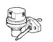
1 RE65265 HAND PRIMER 1 X (SUB FOR RE48048)
2 R54025 WASHER 1 X
3 R26448 O-RING 2 X
4 RE34128 ELBOW FITTING 2 X
5 R67879 GASKET 1 X
6 RE46252 FUEL PUMP 1 X (ROBERT BOSCH)
7 R53899 WASHER 1 X
8 R83490 FITTING 1 X
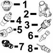
KEY PART NO. PART NAME QTY SERIAL NO. F F F REMARKS
1 RE57151 FUEL LINE 1 X NO. 6
2 RE57150 FUEL LINE 1 X NO. 5
3 RE57149 FUEL LINE 1 X NO. 4
4 R71398 SCREW 5 X
R58186 CLAMP 10 X
R59305 STRAP 5 X
R61144 STRAP 5 X
R74030 CLAMP 1 X
5 RE57148 FUEL LINE 1 X NO. 3
6 RE57147 FUEL LINE 1 -081549 X NO. 2
RE502933 FUEL LINE 1 081550- X NO. 2
7 RE57146 FUEL LINE 1 -081549 X NO. 1
RE502932 FUEL LINE 1 081550- X NO. 1
8 21H1463 CAP SCREW 2 X 0.190" X 7/8"
R59298 STRAP 1 X
R61145 STRAP 1 X
R120184 STRAP 1 X
R59297 HALF CLAMP 2 X
9 R59298 STRAP 1 X
R58186 CLAMP 1 X
R71212 CLAMP 1 X
R74804 CLAMP 1 X
R71398 SCREW 1 X
R61145 STRAP 1 X
R120182 STRAP 1 X
10 21H1463 CAP SCREW 1 X 0.190" X 7/8"
R59297 HALF CLAMP 2 X
R59598 GASKET 2 X
11 RE55662 ABSORBER 1 X
12 24H1884 WASHER 1 X 13/32" X 13/16" X 0.120" 13/32" X
13/16" X 0.120", (NLR)
13 19M7166 CAP SCREW 1 X M10 X 20 M10 X 20
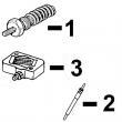
14 RE61593 INJECTION NOZZLE 6 X (A) (ROBERT BOSCH)
R51603 O-RING 6 X
15 R84472 WASHER 6 X 7.360 X 18.160 X 2 MM (0.290" X 0.715"
X 0.079") 7.360 X 18.160 X 2 MM
(0.290" X 0.715" X 0.079")
16 R504057 O-RING 6 087550- X
17 RE501970 ADAPTER 6 087550- X
18 R79604 TUBE NUT 6 087550- X
19 R51937 TUBE NUT 1 X
20 AR85519 PLUG 1 X
21 RE500803 FUEL LINE 1 087550- X
22 R77551 O-RING 6 -087549 X
23 R87082 FITTING 6 -087549 X
24 R79604 TUBE NUT 6 -087549 X
25 R79605 WASHER 6 -087549 X
26 R79606 TEE FITTING 6 -087549 X
27 R51936 SEALING WASHER 11 -087549 X
28 RE15807 FUEL LINE 2 -087549 X
29 RE15808 FUEL LINE 2 -087549 X
30 RE36421 FUEL LINE 2 -087549 X
31 R97061 TEE FITTING 1 -087549 X
(A) 1 ORANGE DOT
(1) POINT ORANGE
(1) ORANGEFARBENER PUNKT
(1) PUNTO ARANCIONE
(1) PUNTO ANARANJADO
(1) ORANGEFAERGAD PUNKT