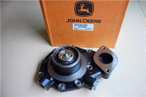
配件详情
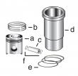
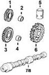
约翰迪尔 3029 2.9T 活塞(米) RE500211
|
|
|
发动机和设备型号
|
从 258,847
代码 4808
引擎号码:
3029TF120
孔径: 4.19 in
106.5 mm
销径 Ø: 1.6250 in (+/- .0002)
41 mm
|
|
|
强鹿JOHN DEERE柴油机配件、发动机配件、发电机组:
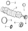
6090HFU75、6068HFU74、6090HFU84、4024TF220、6090HF485 6081HF001、6081AF001、6081TF001、4039DF004、6068HF252、4039DF005、4039DF008、6076TF010、6059TF001、4045HF275、RG6125、6135H458、4045DFM70, 4045TFM75up&injection will begin. as the plunger continues to move down, pressure will rapidly rise to approximately 160,000 kpa (1600 bar) (23,200 psi). injection will continue until the ecu de-energizes the solenoid. the spill valve will then open allowing fuel pressure to drop rapidly. the injector needle will close&injection will stop. ctm188 (20mar01) 03-130-7 powertech 10.5 l & 12.5 l level 6 fuel system 032001 pn=111 electronic fuel system operation 03 130 8 rg,rg34710,1525 –19–30sep97–1/2 low pressure single rail fuel supply system operation rg10667 –un–14dec99 oem applications single rail fuel system a—pre-filter f—fuel transfer pump l—fuel supply pressure o—water drain b—fuel filter inlet from fuel g—euis quick connect port p—fuel temperature sen*** tank h—fuel rail m—fuel filter housing outlet q—water in fuel sen*** c—hand primer i—fuel return from cylinder to fuel tank (low r—fuel filter housing d—vacuum port head pressure regulating valve) s—water separator bowl e—fuel filter outlet to j—fuel pressure sen*** n—high pressure regulating transfer pump (check k—head debris filter valve&housing valve) the fuel transfer pump (f) draws fuel from the fuel tank through the pre-filter (a)&fuel filter. the fuel filter is located in the fuel filter housing (r). the fuel filter housing contains a hand primer pump (c)&a water separator bowl (s), which screws to the bottom of the fuel filter housing. a self-venting water drain valve (o) is mounted on the bottom of the clear bowl. ctm188 (20mar01) 03-130-8 powertech 10.5 l & 12.5 l level 6 fuel system 032001 pn=112 continued on next page electronic fuel system operation 03 130 9 rg,rg34710,1525 –19–30sep97–2/2 fuel flows from the fuel filter outlet (e) to the inlet of the fuel transfer pump which is mounted on the rear of the cylinder head. the pump shaft is coupled to the end of the camshaft. the fuel transfer pump contains a pressure regulating valve for system over-pressure protection. a bypass valve in the pump base allows fuel to bypass the gears during hand priming. fuel flows from the transfer pump into the side of the cylinder head,&then it enters the fuel rail (h). the fuel rail is a drilled passage in the cylinder head that routes fuel to each unit injector. the unused fuel is rejected back from the euis (g) into the fuel rail and returned to the back of the fuel filter housing (i). in this portion of the fuel filter housing, the fuel passes by a fuel pressure sen*** (j),&then it travels through a head debris filter (k), which is a 10 micron filter. after flowing through the head debris filter, the fuel enters a chamber that includes the fuel supply pressure quick connect port (l). once the fuel is in this chamber, it will either travel through the low pressure regulating valve (m)/the high pressure regulating valve (n). if fuel goes through the low pressure regulating valve, it will return to the fuel tank. if fuel goes through the high pressure regulating valve, it will pass the fuel temperature sen*** (p), which is mounted into the fuel filter housing. the fuel will return to the fuel filter to be cleaned,&it will be recirculated through this system. ctm188 (20mar01) 03-130-9 powertech 10.5 l & 12.5 l level 6 fuel system 032001 pn=113 electronic fuel system operation 03 130 10 rg,rg34710,1527 –19–30sep97–1/5 electronic unit injector (eui) operation on the single rail fuel system the electronic unit injector pumping action is created by the up&down movement of the plunger. the plunger movement is caused by the rotation of the camshaft and the rocking action of the rocker arms. the larger return spring will move the plunger up as the camshaft rotates and relaxes the force on the rocker arm. rg,rg34710,1527 –19–30sep97–2/5 rg10422 –un–30nov99 eui fill cycle eui fill cycle - single rail fuel system the electronic unit injector will fill with fuel when the plunger (c) is moving up. fuel from the fuel rail (d) enters fuel passage (a) of the unit injector. fuel flows past the open spill valve (e) into fuel passage (b). passage b routes fuel into the plunger cylinder (f), which fills as the plunger moves up. continued on next page ctm188 (20mar01) 03-130-10 powertech 10.5 l & 12.5 l level 6 fuel system 032001 pn=114 electronic fuel system operation 03 130 11大同约翰迪尔活塞RE70688信息,鹤岗约翰迪尔强鹿柴油发动机凸轮轴下衬套哪里买,白山美国JohnDeere柴滤RE507284市场报价,临沂约翰迪尔强鹿4045柴油发动机大修包诚信推荐,平顶山johndeere约翰迪尔强鹿柴油机气门室盖垫厂家批发,黔西南约翰迪尔6068柴油机排气门异管批发商,驻马店强鹿柴油发电机组电脑板的价格,宜宾约翰迪尔节温器RE540550找哪家, rg,rg34710,1527 –19–30sep97–3/5 rg10423 –un–30nov99 eui vent cycle eui vent cycle - single rail fuel system the vent cycle begins when the plunger (a) nears the top of the fill cycle stroke. at this point a vent port (b) will be uncovered&fuel&any trapped air can flow to the fuel rail (c). continued on next page ctm188 (20mar01) 03-130-11 powertech 10.5 l & 12.5 l level 6 fuel system 032001 pn=115 electronic fuel system operation 03 130 12 rg,rg34710,1527 –19–30sep97–4/5 rg10424 –un–30nov99 eui pumping cycle eui pumping cycle - single rail fuel system the pumping cycle begins when the camshaft lobe pushes on the rocker arm to cause the plunger (f) to start moving down. during the first downward movement of the plunger, the vent port (c) will close. further downward movement of the plunger will force fuel from the plunger cylinder (d). fuel will flow out fuel passage (b), through the open spill valve (e), into fuel passage (a)&back to the fuel rail (g). this flow will continue until the injection cycle begins. continued on next page ctm188 (20mar01) 03-130-12 powertech 10.5 l & 12.5 l level 6 fuel system 032001 pn=116 electronic fuel system operation 03 130 13 rg,rg34710,1527 –19–30sep97–5/5 rg10425 –un–30nov99 eui injection cycle eui injection cycle - single rail fuel system the injection cycle will start when the engine control unit (ecu) energizes the eui solenoid (a). this will occur during the downward stoke of the plunger. the energized solenoid will close the spill valve (b). with the spill valve closed, fuel can not escape from the plunger cylinder (c). the downward movement of the plunger (d) will cause the fuel pressure to rise. when the pressure reaches 30,000 kpa (300 bar) (4350 psi), the injector needle (e) will start to move up&injection will begin. as the plunger continues to move down, pressure will rapidly rise to approximately 160,000 kpa (1600 bar) (23,200 psi). injection will continue until the ecu de-energizes the solenoid. the spill valve will then open allowing fuel pressure to drop rapidly. the injector needle will close&injection will stop. ctm188 (20mar01) 03-130-13 powertech 10.5 l & 12.5 l level 6 fuel system 032001 pn=117 electronic fuel system operation 03 130 14 ctm188 (20mar01) 03-130-14 powertech 10.5 l & 12.5 l level 6 fuel system 032001 pn=118 group 140 electrical control system operation 03 140 1 rg,rg34710,1528 –19–20nov00–1/1 electronic control system glossary of terms actuator a device controlled by the (ecu) to perform a certain function. analog signal which has a continuous range of possible voltages. usually 0 to 5 volt/0 to 12 volt signals. boost air pressure in the intake manifold. can controller area network. the network on vehicles that allows communication between controllers. dtc diagnostic trouble code. a code which is stored in the ecu’s memory when the ecu detects a problem in the electronic control system. dst diagnostic scan tool. the tool used to read&clear dtcs, read sen***&actuator data,&perform engine tests. the dst consists of an windows (’95/’98)/nt compatible computer&2 kits available from john deere distribution service center (dsc): jdis121 - ecu communication hardware kit,&jdis122 - ecu communication software kit. digital a signal which consists of only two-volt levels — usually 0 volts&+5 volts. ect engine coolant temperature (sen***). measures the temperature of the engine coolant. see measuring temperature later in this group for details. ecu engine control unit. the computer which controls the fuel, air,&ignition systems on the engine. see engine control unit (ecu) later in this group for details. eui electronic unit injector. an eui is an electronically controlled injection pump&injector combined. the ecu controls the start of injection&the amount of fuel injected by energizing&de-energizing the solenoid in the eui valve housing. see electronic unit injector (eui) operation on the dual rail fuel system/electronic unit injector (eui) operation on the single rail fuel system in group 130 for details. fmi failure mode identifier. the second part of a two-part code that identifies control system fault codes according to the j1939 standard. the fmi identifies the type of failure that has occurred. the first half of the code is the suspect parameter number (spn). j1587/j1708 the society of automotive engineers (sae) standard for the electronic components of heavy duty vehicles. j1587 is the software standard. j1708 is the hardware standard. mat manifold air temperature (sen萍乡强鹿R123461风扇皮带诚信推荐,运城强鹿6081柴油机进气门的价格,铜仁强鹿压实机柴油机配件一级代理,乌鲁木齐强鹿6068柴油机气门油封供应商,盘锦发电机组零部件强鹿的价格,安康约翰迪尔水泵RE505980价格,澳门离岛强鹿柴油机水泵厂家供应,阿拉善约翰迪尔6068TF158柴油机配件代理商,甘孜强鹿电子燃油泵RE502711哪家买,镇江JOHNDEERE强鹿4045TF275配件诚信推荐,平顶山约翰迪尔柴油机进气门R84618哪家好,柳州约翰迪尔4045柴油机气门室盖螺丝R85363厂家价格,西双版纳约翰迪尔装载机发动机活塞批发,新竹约翰迪尔强鹿4045柴油机衬垫套哪家好,衡水johndeere约翰迪尔强鹿机油泵价格,日喀则约翰迪尔柴油滤芯价格,郴州约翰迪尔温度传感器RE522823多少钱,). measures the temperature of the air in the intake manifold. see measuring temperature later in this group for details. multi-state a type of throttle that allows the engine to run between 1-3 set engine speeds. pdm parallel data module. device used as part of the dst that allows communication with the ecu. prom programmable, read-only memory. the computer chip which contains the calibration information for the engine control system. see engine control unit (ecu) later in this group for details. pwm pulse width modulation. a digital signal (not analog) which consists of a pulse generated at a fixed frequency. when an actuator is controlled by a pwm signal, the on time of the signal is increased/decreased (modulated) to increase/decrease the output of the actuator. ram random access memory. the portion of computer memory within the ecu which changes as the engine is running&is stored while the engine is off. see engine control unit (ecu) later in this group for details. sen*** device used by the ecu to monitor various engine parameters. spn suspect parameter number. the first half of a two-part code that identifies control system fault codes according to the j1939 standard. the spn identifies the system/component that has the failure. the second half of the code is the failure mode identifier (fmi). tps throttle position sen***. the tps measures the position of the throttle, which is controlled by the machine operator. see measuring throttle position later in this group for details. wif water in fuel sen***. the wif detects water in fuel in the water separator bowl on the fuel filter housing. ctm188 (20mar01) 03-140-1 powertech 10.5 l & 12.5 l level 6 fuel system 032001 pn=119 electrical control system operation 03 140 2 rg,rg34710,1529 –19–30sep97–1/2 electronic control system overview rg10419 –un–30nov99 electronic control system overview for a dual rail fuel system a—cam position sen*** e—oil pressure sen*** i—mat sen*** l—wif sen*** b—crank position sen*** f—fuel temperature sen*** j—map sen*** connector m—fuel pressure sen*** c—eui harness connector g—diagnostic connector k—program performance d—ect sen*** h—ecu connector continued on next page ctm188 (20mar01) 03-140-2 powertech 10.5 l & 12.5 l level 6 fuel system 032001 pn=120 electrical control system operation 03 140 3 rg,rg34710,1529 –19–30sep97–2/2 rg10619 –un–30nov99 electronic control system overview for a single rail fuel system a—cam position sen*** e—oil pressure sen*** i—mat sen*** l—wif sen*** b—crank position sen*** f—fuel temperature sen*** j—map sen*** connector m—fuel pressure sen*** c—eui harness connector g—diagnostic connector k—program performance d—ect sen*** h—ecu connector the electronic control system serves as an engine governor by controlling the electronic unit injectors (euis) so that fuel is delivered according to a given set of engine conditions, in precise amounts,&at a precise time in relation to piston position. in order to achieve this, the control system performs the following functions: ? constantly monitor engine operating conditions ? precisely determines piston position ? deliver optimum amount of fuel for a given set of operating conditions ? deliver fuel at optimum piston position ? provide multiple control modes ? perform self-diagnosis ctm188 (20mar01) 03-140-3 powertech 10.5 l & 12.5 l level 6 fuel system 032001 pn=121 electrical control system operation 03 140 4 rg,rg34710,1530 –19–30sep97–1/1 electronic control system operation engine starting mode when the key is turned to the “on” position, a switched power voltage is sent to the ecu allowing the ecu to energize. this allows the ecu to “boot-up” and ready itself for engine start. note: if a wiring problem prevents the key on signal from getting to the ecu, the engine will not start. as soon as the ecu determines using the crankshaft position sen*** input that the engine is cranking, it will determine using the camshaft position sen*** input when cylinder number 1 is coming to top-dead-center at the end of the compression stroke. it will then start injecting fuel when the next cylinder in the firing order (cylinder number 5) is at the correct position before top-dead-center at the end of compression. to provide cold temperature enrichment, the amount of fuel injected is based on the temperature measured by the engine coolant temperature (ect) sen***. at this point, the engine will start&the ecu will go into the running mode. engine running mode in the running mode, the ecu monitors information from the various sen***s, then determines the optimum amount of fuel to inject&the optimum injection timing in order to allow the engine to develop high power while maintaining low exhaust emission output. the camshaft&crankshaft position sen***s allow the ecu to precisely determine piston position in relation to top-dead-center so that the ecu can command the correct electronic unit injector (eui) solenoid at the correct time. the ecu controls fuel delivery by energizing&de-energizing the individual solenoids that open&close the eui spill valves. when the ecu energizes the eui solenoid, the spill valve closes&injection begins. when the correct amount of fuel has been injected, the ecu de-energizes the solenoid, causing the spill valve to open,&fuel injection to stop. rg,rg34710,1531 –19–30sep97–1/1 monitoring engine parameters in order for the electronic control system to deliver fuel according to a given set of operating conditions, the following parameters are monitored by the ecu: ? engine coolant temperature (ect) ? manifold air temperature (mat) ? fuel temperature ? loss of coolant temperature switch ? fuel pressure ? oil pressure ? air vacuum switch ? throttle position ? engine speed ? water in fuel sen*** (wif) ctm188 (20mar01) 03-140-4 powertech 10.5 l & 12.5 l level 6 fuel system 032001 pn=122 electrical control system operation 03 140 5 rg,rg34710,1532 –19–30sep97–1/4 measuring temperature the engine coolant temperature (ect) sen***, the manifold air temperature (mat) sen***,&the fuel temperature sen*** are all temperature sensitive variable resistors. the sen***s’ resistance goes down as the temperature that it is exposed to goes up (negative temperature coefficient). the engine control unit (ecu) sends 5 volts to the sen***, monitors the voltage drop across the sen***,&compares the voltage drop to preprogrammed values in the ecu’s memory in order to determine temperature. in addition to temperature sen***s, some applications use temperature switches. the loss of coolant temperature switch is an example. temperature switches close when a specific temperature is reached. rg,rg34710,1532 –19–30sep97–2/4 rg10625 –un–30nov99 ect sen*** a—ect sen*** ect (engine coolant temperature) sen*** the ect (engine coolant temperature) sen*** (a) is located in top of the thermostat housing. the ecu monitors coolant temperature for: ? engine protection purposes — see engine protection later in this group. ? starting fuel quantity determination — the ecu will adjust the amount of fuel delivered during start-up based on initial ect readings. ? idle speed determination — in order to speed engine warm-up, the ecu will increase idle speed after start-up if a low coolant temperature is measured. continued on next page ctm188 (20mar01) 03-140-5 powertech 10.5 l & 12.5 l level 6 fuel system 032001 pn=123 electrical control system operation 03 140 6 rg,rg34710,1532 –19–30sep97–3/4 rg10627 –un–30nov99 mat sen*** a—mat sen*** mat (manifold air temperature) sen*** the mat (manifold air temperature) sen*** (a) is an optional component that is located on/near the intake manifold. the ecu monitors manifold air temperature for engine protection purposes. see engine protection later in this group. rg,rg34710,1532 –19–30sep97–4/4 rg10628 –un–30nov99 dual rail fuel temperature sen阳泉约翰迪尔W230联合收割机发动机配件哪里买,邢台强鹿柴油机曲轴RE515785厂家供应,吉林约翰迪尔采棉机re531703强鹿柴油滤芯哪家好,齐齐哈尔约翰迪尔7830拖拉机发动机配件信息,鄂尔多斯强鹿机滤RE58935价格,自贡约翰迪尔前油封RE505515信息,贺州JohnDeere发动机活塞销R502755找哪家,阿坝约翰迪尔发动机滤清器批发,巴中强鹿发动机四配套IK526975批发价,商丘约翰迪尔后齿轮R63326批发,赣州约翰迪尔发动机出油阀价格行情,乌海约翰迪尔止推轴承瓦RE529320哪里买,南平约翰迪尔E210/E210LC挖掘机发动机配件价格行情,咸阳约翰迪尔曲轴位置传感器批发商,白城美国强鹿配件实时报价价格,南昌约翰迪尔强鹿4045柴油机止推轴承RE65168批发价,上饶约翰迪尔甘蔗收割机发动机配件批发商,汉中约翰迪尔强鹿3029柴油机空气加热器市场报价,韶关约翰迪尔滤清器RE60021厂家批发,武威约翰迪尔RE27358连杆瓦诚信推荐,朔州约翰迪尔6090柴油机机油冷却器多少钱,阜新强鹿进气门R84618的价格,滨州约翰迪尔联合收割机发动机活塞价格,阜阳强鹿6090柴油发动机排气门批发价,衢州强鹿6081柴油发动机修理包批发价,云浮强鹿传感器RE522823批发商,荆州johndeere约翰迪尔强鹿柴油发动机机滤RE58935公司,南京JohnDeere3029衬垫套供货商,四平johndeere约翰迪尔强鹿柴油机中冷器供应商, rg10626 –un–30nov99 single rail fuel temperature sen*** a—fuel temperature sen*** on a dual rail fuel system b—fuel temperature sen*** on a single rail fuel system fuel temperature sen*** the fuel temperature sen*** is located on the fuel manifold at the back of the cylinder head on the dual rail fuel system (a). on the single rail fuel system, it is located on the fuel filter housing behind the fuel filter (b). using the fuel temperature measurement, the ecu will determine fuel density,&adjust fuel delivery accordingly. loss of coolant temperature switch the loss of coolant temperature switch is an optional component not included on all applications. it is a normally open temperature sensitive switch. the switch is located near the back of the cylinder head. when engine coolant is at the proper level, the temperature sensitive end of the switch is submerged in coolant,&the switch contacts will be open. if coolant level drops, the switch will no longer be submerged causing the temperature of the switch to raise beyond the point that causes the switch contacts to close. the ecu will detect that the switch is closed,&protect the engine from overheating damage by derating/shutting down the engine. see engine protection later in this group for more information. ctm188 (20mar01) 03-140-6 powertech 10.5 l & 12.5 l level 6 fuel system 032001 pn=124 electrical control system operation 03 140 7 rg,rg34710,1533 –19–30sep97–1/3 measuring pressure the system’s pressure sen***s are pressure sensitive variable resistors. as the pressure changes, sen*** resistance changes. the ecu sends a 5 volt reference voltage to the sen***, monitors the voltage returning on the sen*** signal wire,&compares the voltage drop to preprogrammed values in the ecu’s memory to determine pressure. in addition to pressure sen***s, some applications use pressure switches. the air vacuum switch is an example of this type of switch. pressure switches close when a specific pressure is reached. rg,rg34710,1533 –19–30sep97–2/3 rg10623 –un–30nov99 fuel pressure sen*** a—fuel pressure sen*** on single rail fuel system fuel pressure sen*** the fuel pressure sen*** is used on some applications that use the single rail fuel system. the sen*** is located behind the fuel filter in the fuel manifold (a). the ecu monitors fuel pressure for engine protection purposes. see engine protection later in this group for more information. continued on next page ctm188 (20mar01) 03-140-7 powertech 10.5 l & 12.5 l level 6 fuel system 032001 pn=125 electrical control system operation 03 140 8 rg,rg34710,1533 –19–30sep97–3/3 rg10620 –un–30nov99 oil pressure sen*** a—oil pressure sen*** oil pressure sen*** the oil pressure sen*** is an optional component that is located in the main engine galley/in the oil cooler (a). the ecu monitors oil pressure for engine protection purposes. see engine protection later in this group for more information. air vacuum switch the air vacuum switch is an optional component that is used to test for restrictions in the air filter. it’s location may vary depending on application. the ecu monitors this for engine protection purposes. see engine protection later in this group. dpsg,rg40854,456 –19–14oct99–1/1 water in fuel sen*** rg10624 –un–30nov99 water in fuel sen*** a—water in fuel sen*** the water in fuel sen*** is an optional sen*** that is located in the water separator bowl in the fuel filter (a). the ecu monitors this for engine protection purposes. see engine protection later in this group. ctm188 (20mar01) 03-140-8 powertech 10.5 l & 12.5 l level 6 fuel system 032001 pn=126 electrical control system operation 03 140 9 rg,rg34710,1534 –19–30sep97–1/1 measuring throttle position the 10.5&12.5 l engines have the option of operating with a pulse-width-modulated (pwm) throttle signal, an analog throttle position sen*** output signal, multi-state throttle,/can throttle. in some applications, a backup throttle is used. pulse-width-modulated (pwm) throttle the pwm throttle signal is sent to the ecu by another controller. the pwm signal is a square wave signal with a constant frequency. the pulse width of the signal varies&indicates the desired throttle opening. analog throttle an analog throttle signal comes from a potentiometer-type sen***. the ecu converts the voltage returning from the potentiometer into a percent of full throttle signal. multi-state throttle the multi-state throttle is used when a few fixed engine speeds are desired. can throttle can throttle is information sent to the ecu by another controller over can of the desired throttle position. rg,rg34710,1536 –19–30sep97–1/4 determining engine speed&piston position engine speed&precise piston position in relation to top-dead-center (tdc) is determined by the ecu using the crankshaft position sen***&the crankshaft timing wheel. cylinder identification in relation to the engine firing order is determined by the ecu using the camshaft position sen***,&the camshaft timing wheel. both sen***s operate by detecting notches on a timing wheel. when a notch on the timing wheel is directly under the sen***, a voltage is induced. the ecu monitors this voltage to determine timing wheel position. continued on next page ctm188 (20mar01) 03-140-9 powertech 10.5 l & 12.5 l level 6 fuel system 032001 pn=127 electrical control system operation 03 140 10 rg,rg34710,1536 –19–30sep97–2/4 rg8378 –un–23nov97 crankshaft timing wheel rg8379 –un–26nov97 crankshaft timing wheel notches crankshaft position the crank timing wheel (a) is located on the front of the crankshaft, behind the pressed-on crank gear (b). the timing wheel is composed of 54 notches, divided into 3 groups of 18 notches. before the first notch in each group is a flat area equal to 18° of crankshaft rotation, the following 17 notches are separated by 6° of crankshaft rotation. each group of 18 notches&a flat area is equal to 120°,/a third of a full turn. continued on next page ctm188 (20mar01) 03-140-10 powertech 10.5 l & 12.5 l level 6 fuel system 032001 pn=128 electrical control system operation 03 140 11 rg,rg34710,1536 –19–30sep97–3/4 rg8380 –un–23nov97 camshaft timing wheel rg8381 –un–26nov97 camshaft timing wheel notches camshaft position the camshaft timing wheel (a) consists of 7 notches cut into the center journal of the camshaft. six of the 7 notches are evenly spaced at 60° center-to-center. each of the 6 notches correspond to a cylinder; the 7th notch is located 15° center-to-center before the notch that identifies cylinder number 1. the ecu has the engine firing order stored in memory, therefore it knows that following the notch identifying cylinder 1 will be the notch identifying cylinder 5 etc. the camshaft timing wheel turns at one half the speed of the crankshaft timing wheel. continued on next page ctm188 (20mar01) 03-140-11 powertech 10.5 l & 12.5 l level 6 fuel system 032001 pn=129 electrical control system operation 03 140 12 rg,rg34710,1536 –19–30sep97–4/4 rg8383 –19–18sep98 crankshaft/camshaft timing wheels relationship crankshaft/camshaft position relationship when the cam position sen*** detects the extra notch on the cam timing wheel, the ecu is informed that the notch identifying cylinder 1 is 15° of crank rotation away from the cam position sen***,&the center of the flat area on the crank timing wheel is 30° of crank rotation away from the crank position sen***. one timing cycle will then begin when the cam position sen*** is directly in the center of a notch on the cam timing wheel. at this time, the crank position sen*** is directly in the center of a flat area on the crank timing wheel,&piston number 1 is 69° of crankshaft rotation away from tdc on the compression stroke. during the previous 120°, the ecu calculated engine speed&determined the optimum time to start injecting fuel&the optimum time to stop injecting (determines fuel amount). it then monitors each crank timing notch until the time to start injection occurs, at which time it energizes the electronic unit injector (eui) solenoid to start fuel delivery. it continues to monitor each crank timing notch until the time to end injection occurs, at which time it will deenergize the eui solenoid to stop fuel delivery. in the event of a crank/cam position sen*** failure, a “limp-home” mode will allow the ecu to operate with only one position sen*** input. if the crank position sen*** fails, engine power will be low. if the cam position sen*** fails, long cranking times will be required to start the engine. if both sen***s fail, the engine will die&won’t restart. ctm188 (20mar01) 03-140-12 powertech 10.5 l & 12.5 l level 6 fuel system 032001 pn=130 electrical control system operation 03 140 13 ctm188 (20mar01) 03-140-13 powertech 10.5 l & 12.5 l level 6 fuel system 032001 pn=131 electrical control system operation 03 140 14 rg,rg34710,1537 –19–30sep97–1/2 engine control unit (ecu) rg10417 –19–20dec00 deere level 6 ecu the engine control unit (ecu) is the “brains” of the electronic control system. the ecu is a self-contained unit containing electronic circuitry and computer software which together perform the following functions: ctm188 (20mar01) 03-140-14 powertech 10.5 l & 12.5 l level 6 fuel system 032001 pn=132 continued on next page electrical control system operation 03 140 15 rg,rg34710,1537 –19–30sep97–2/2 ? convert the electrical signals from the various sen***s into digital signals ? make decisions of optimum fuel quantity and injection timing based on information from various sen***s ? limit maximum fuel for operation on multiple power curves ? control fuel delivery ? provide min-max/all-speed governing ? perform self diagnosis on the control system ? store trouble codes in memory the ecu connects to the wiring harness through a white, 48-way ecu connector, which is composed of a 30 terminal ecu connector&an 18 terminal ecu connector,&a black, 60-way ecu connector, which is composed of two 30 terminal connectors. the connectors are marked by letters&numbers to help identify the terminals. the ecu is composed of the following subsystems: analog/digital converters this portion of the ecu converts the analog voltage signals from the various sen***s into digital signals that the central processing unit can “understand”. central processing unit (cpu) the central processing unit performs the mathematical computations&logical functions that are necessary in controlling injection fuel quantity&injection timing. the cpu commands the electronic unit injectors (euis)&controls the self diagnostic system. memory the ecu contains 3 different types of memory: — random access memory - ram the ram is like the working desk top of the ecu. data from the various sen***s&the results of various calculations are temporarily stored in ram. information in ram is lost when battery voltage to the ecu is removed. — read only memory - rom the rom contains programmed information. information in rom can only be read, not changed. rom information is retained when battery voltage is removed. — electrical erasable programmable read only memory - eeprom the eeprom contains information programmed in at the factory including engine specific data, and application data. information in the eeprom is retained when battery voltage is removed. ctm188 (20mar01) 03-140-15 powertech 10.5 l & 12.5 l level 6 fuel system 032001 pn=133 electrical control system operation 03 140 16 dpsg,rg40854,457 –19–14oct99–1/1 cruise control operation the ecu is available with&without the cruise control function. it is an off-road cruise control that maintains constant engine speed under varying load conditions. this function is especially intended for field applications where an operator faces the need to turn the vehicle around at the end of each row. this cruise control allows the driver to use the throttle and/or brake to turn the vehicle around. when ready to resume field operations, the operator brings the engine speed above 1300 rpm&activates the cancel/resume function again to resume cruise speed. an internal timer gives the operator one minute to complete the turnaround maneuver. the cruise control has the normal functions of: ? cruise control power “on”/“off” ? “set”/“bump up” engine speed ? “resume”/“bump down” engine speed ? vehicle brake/clutch pedal to disengage cruise control on 12 volt ecus, the engine speed can be set from two different locations. the primary location would normally be in the cab of the vehicle&is used to set a constant engine speed while the vehicle is being driven. the secondary cruise control is normally used in a location that provides pto speed control&is used with the engine in “neutral”/out of gear. both locations have the normal cruise control functions. ctm188 (20mar01) 03-140-16 powertech 10.5 l & 12.5 l level 6 fuel system 032001 pn=134 electrical control system operation 03 140 17 dpsg,rg40854,458 –19–14oct99–1/1 engine protection there are two levels of engine protection: ? warning — the warning lamp (if equipped) turns on. causes: – lower than normal oil pressure – engine coolant temperature higher than normal – higher than normal manifold air temperature – lower than normal fuel supply pressure – higher than normal fuel supply pressure – water in fuel detected – high air filter restriction – power derates ? shutdown — the shutdown lamp (if equipped) turns on. causes: – extremely low oil pressure – extremely high engine coolant temperature – loss of coolant – extremely low fuel supply pressure – water in fuel continuously detected there are three different engine protection programs available: ? no protection — the operator must reduce the speed of the engine when the “warning”trouble light is on,&shutdown the engine when a “shutdown” trouble light is on. if a “shutdown” trouble light occurs, it is the responsibility of the operator to shut down the engine. ? engine protection without shutdown — the engine will derate either due to a “warning”/a “shutdown” trouble light. if a “shutdown” trouble light occurs, it is the responsibility of the operator to shutdown the engine. ? engine protection with shutdown — the engine will derate either due to a “warning”/a “shutdown” trouble light. if a “shutdown” trouble light is detected, the ecu will shut down the engine in 30 seconds. if the problem is corrected within the 30 second delay period, the power will increase at a particular rate until full power is reached. the “warning” fault lamp will remain on until the power returns to normal, and at that time, it will shut off. shutdown override note: holding the shutdown override switch continuously “on” will not reset the 30 second timer. the engine protection shutdowns can be overridden for 30 seconds at a time. this can be used to move a vehicle to a safe location. each time the switch is pushed, the shutdown timer is reset to 30 seconds, and the engine will run in a derated power mode. ctm188 (20mar01) 03-140-17 powertech 10.5 l & 12.5 l level 6 fuel system 032001 pn=135 electrical control system operation 03 140 18 dpsg,rg40854,459 –19–14oct99–1/2 different derate programs note: the derate programs shown below apply to oem engine applications that contain engine protection. other applications may have similar derate programs. refer to specific machine manual for application derate programs. low oil pressure protection ? warning: a power derate of 2% per minute with a maximum derate of 20% of rated power will start if the “warning” fault lamp is set. if oil pressure increases over the “warning” fault pressure, the power will increase at the rate of 2% per minute until full power is reached. ? shutdown: a power derate of 20% per minute with a maximum derate of 40% of rated power occurs if oil pressure becomes lower than the “shutdown” fault pressure. if this fault stays on for 30 seconds, the engine will shut down. if oil pressure begins to increase above the “shutdown” fault pressure, the “warning” fault will activate. the power derate will revert to the “warning” fault. note: shutdown only occurs on engines that have the option in their ecu. high ect (engine coolant temperature) protection ? warning: a power derate of 2% per minute with a maximum derate of 20% of rated power will start if the “warning” fault lamp is set. if ect decreases below the “warning” fault pressure, the power will increase at the rate of 2% per minute until full power is reached. ? shutdown: a power derate of 20% per minute with a maximum derate of 40% of rated power occurs if ect exceeds the “shutdown” fault temperature. if ect does not decrease below the “shutdown” fault temperature within 30 seconds, the engine will shut down. if ect decreases below the “shutdown” fault temperature within 30 seconds, the power derate will divert to the “warning” curve. note: shutdown only occurs on engines that have the option in their ecu. loss of coolant protection ? shutdown: a power derate of 20% per minute with a maximum derate of 40% of rated power occurs if the coolant level becomes low. if the loss of coolant switch does not reset within 30 seconds, the engine will shutdown. if the switch resets within 30 seconds, the power KEY PART NO. PART NAME QTY SERIAL NO. F F F REMARKS
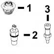
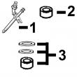
1 .. PACKING 1 X (ORDER RE504827)
2 .. PACKING 2 X (ORDER RE504827)
3 RE506868 FITTING 1 X (IN)
RE503796 FITTING 1 X (OUT)
4 R54025 WASHER 1 X
5 RE65265 HAND PRIMER 1 X
6 RE503803 FUEL PUMP 1 X
1600A-1645I POWERTECH 8.1 L OEM ENGINE (ESN -199999) PC2527 (23-SEP-02)
KEY PART NO. PART NAME QTY SERIAL NO. F F F REMARKS
1 RE47431 FUEL LINE 1 X NO. 6
2 RE47430 FUEL LINE 1 X NO. 5
3 RE47429 FUEL LINE 1 X NO. 4
4 R120185 BOLT 5 X
R58186 CLAMP 10 X
R120181 STRAP 5 X
R120182 STRAP 5 X
5 RE47428 FUEL LINE 1 X NO. 3
6 RE47427 FUEL LINE 1 -080424 X
RE502930 FUEL LINE 1 080425- X NO. 2, (SUB FOR RE47427)
7 RE47426 FUEL LINE 1 -080424 X
RE502929 FUEL LINE 1 080425- X NO. 1, (SUB FOR RE47426)
8 R120186 BOLT 2 X
R71212 CLAMP 1 X
R120183 STRAP 1 X
R120184 STRAP 1 X
R59297 HALF CLAMP 2 X
9 R59305 STRAP 1 X
R58186 CLAMP 1 X
R74030 CLAMP 1 X
R74804 CLAMP 1 X
R120186 BOLT 1 X
R120181 STRAP 1 X
R120182 STRAP 1 X
10 R120185 BOLT 1 X
R59297 HALF CLAMP 2 X
R120183 STRAP 2 X
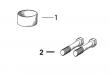
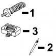
11 RE55662 ABSORBER 1 X
12 24H1884 WASHER 1 X 13/32" X 13/16" X 0.120" 13/32" X
13/16" X 0.120"
13 19M7166 CAP SCREW 1 X M10 X 20 M10 X 20
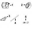
14 RE64184 INJECTION NOZZLE 6 X (A) (ROBERT BOSCH)
R51603 O-RING 6 X
15 R84472 WASHER 6 X 7.360 X 18.160 X 2 MM (0.290" X 0.715"
X 0.079") 7.360 X 18.160 X 2 MM
(0.290" X 0.715" X 0.079")
16 R504057 O-RING 6 087550- X
17 RE501970 ADAPTER 6 087550- X
18 R79604 TUBE NUT 6 087550- X
19 R51937 TUBE NUT 1 X
20 AR85519 PLUG 1 X
21 RE500803 FUEL LINE 1 087550- X
22 R77551 O-RING 6 -087549 X
23 R87082 FITTING 6 -087549 X
24 R79604 TUBE NUT 6 -087549 X
25 R79605 WASHER 6 -087549 X
26 R79606 TEE FITTING 6 -087549 X
27 R51936 SEALING WASHER 11 -087549 X
28 RE15807 FUEL LINE 2 -087549 X
29 RE15808 FUEL LINE 2 -087549 X
30 RE36421 FUEL LINE 2 -087549 X
31 R97061 TEE FITTING 1 -087549 X
(A) 2 PINK DOTS
(2) POINT ROSE
(2) ROSAFARBENER PUNKT
(2) PUNTO ROSA
(2) PUNTO ROSADA
(2) ROSAFAERGAD PUNKT
POWERTECH 8.1 L OEM ENGINE (ESN -199999) PC2527 (23-SEP-02) 1600A-1647
1600A-1648 POWERTECH 8.1 L OEM ENGINE (ESN -199999) PC2527 (10-DEC-02)
KEY PART NO. PART NAME QTY SERIAL NO. F F F REMARKS
1 R60277 SNAP RING 1 X
2 R375R O-RING 1 X
3 R60279 NUT 1 X
4 R60278 SNAP RING 1 X
5 .. NOZZLE HOLDER 1 X (SUB RE64184 OR SE500184)
6 R83720 WASHER 1 X 1.02 MM (.0402")
R83721 WASHER 1 X 1.08 MM (.0425")
R83722 WASHER 1 X 1.12 MM (.0441")
R83723 WASHER 1 X 1.18 MM (.0465")
R83724 WASHER 1 X 1.22 MM (.0480")
R83725 WASHER 1 X 1.28 MM (.0504")
R83726 WASHER 1 X 1.30 MM (.0512")
R83727 WASHER 1 X 1.38 MM (.0543")
R83728 WASHER 1 X 1.42 MM (.0559")
R83729 WASHER 1 X 1.48 MM (.0583")
R83730 WASHER 1 X 1.50 MM (.0591")
R83731 WASHER 1 X 1.58 MM (.0622")
R83732 WASHER 1 X 1.60 MM (.0630")
R83733 WASHER 1 X 1.68 MM (.0661")
R83734 WASHER 1 X 1.70 MM (.0669")
R83735 WASHER 1 X 1.78 MM (.0701")
R83736 WASHER 1 X 1.82 MM (.0717")
R83737 WASHER 1 X 1.88 MM (.0740")
R83738 WASHER 1 X 1.90 MM (.0748")
R83739 WASHER 1 X 1.98 MM (.0780")
7 R108699 SPRING 1 X
8 R108700 SEAT 1 X
9 R108701 PLATE 1 X
10 RE48360 NOZZLE 1 X (7 X .240)
11 R127176 NUT 1 X
12 R84472 WASHER 1 X
13 RE64184 INJECTION NOZZLE 6 X (A) (ROBERT BOSCH)
SE500184 INJECTION NOZZLE 6 X (REMANUFACTURED)
(A) (2) PINK DOTS
(2) POINT ROSE
(2) ROSAFARBENER PUNKT
(2) PUNTO ROSA
(2) PUNTO ROSADA
(2) ROSAFAERGAD PUNKT