配件详情
约翰迪尔 6068T/H 6.8T/H 活塞(米)RE507758 排放 2 & 3
|
|
|
发动机和设备型号
|
孔径:
4.19 in 106.5 mm
销径 Ø:
1.6250 in (+/- .0002) = 41mm
发动机型号:
6068HF475
|
|
|
美国强鹿JOHN DEERE柴油机配件、发动机配件、发电机组: 3029DF120、3029TF158、3029TFU80、3029HFU70、4045HF280、4045TF002、3029DF128、30294045TF258、4045TF275、4045TF220、4045HF285、4045TF258、4045TFU70、4045HF285V07、4045TF220、4045TF120、6068HF120、6068HF475、6068TF220、6068TF001、6068HF158、6135HF485communication software kit, available from john deere. the compression test is used to compare the compression of each cylinder to the average compression of all cylinders. the test will help determine if a cylinder has low compression compared to all other cylinders. during the test, the engine control unit (ecu) will disable the engine from starting (by not pulsing the unit injectors), then measure the time it takes the piston of each cylinder to accelerate through&past tdc. a piston that accelerated faster than the rest would indicate that cylinder has lower compression than the other cylinders. the compression test cannot determine the true compression pressure of any cylinder, it can only compare each cylinder to the average. the test results are only a guide to help determine if a cylinder has lower compression. the results alone should not be used as a conclusive reason for performing any major engine work. other information such as the results of the cylinder misfire test&other engine diagnostic procedures should be used to accurately determine the source of an engine problem. before executing the compression test ? warm engine to normal operating temperature ? repair the cause of any diagnostic trouble codes (dtcs) note: the ecu will not allow the test to run if there are any active dtcs. ? ensure that the battery&starter are in good working condition performing the compression test 1. engine off. 2. select compression test on the dst. 3. follow instruction given by the dst. the dst will instruct that the engine be cranked for up to 15 seconds. typically, it should take less than 5 seconds. the dst should be observed carefully for instructions during the test. the dst will inform the test operator if the test was not successfully completed. if the test was successfully completed, the results will be displayed on the screen. results shown will represent each cylinders’ compression as a percentage in relation to the average of all cylinders. if any cylinder is more than 10% below the rest, that indicates the cylinder’s compression is lower than the rest. note: it is recommended that the test be run at least 3 times to ensure repeatable, accurate results. further engine diagnostics should be performed to determine the cause of low compression. ctm188 (20mar01) 04-160-17 powertech 10.5 l & 12.5 l level 6 fuel system 032001 pn=205 trouble code diagnostics&tests 04 160 18 dpsg,rg40854,358 –19–12oct99–1/1 diagnostic scan tool (dst) engine test instructions— cylinder cutout test the diagnostic scan tool (dst) consists of a windows (’95, ’98/2000)/nt compatible computer, jdis121 - ecu communication hardware kit,&jdis122 - ecu communication software kit, available from john deere. the cylinder cutout test is used to aid in identifying a cylinder that is having a problem/to help in diagnosing mechanical/intermittent problems. during the test, the engine control unit (ecu) will disable the cylinder(s) that the technician selects on the dst. more than one cylinder can be selected at a time, and can be performed while operating the vehicle under the conditions that the problem occurs. the cylinder cutout test can not determine if an engine is developing low power. the test is only a guide to help determine if there is a problem in a cylinder. the results alone should not be used as a conclusive reason for replacing an electronic unit injector (eui). other information such as the results of a compression test&other engine diagnostic procedures should be used to accurately determine the source of the engine problem. before executing the cylinder cutout test ? warm engine to normal operating temperature ? repair the cause of any diagnostic trouble codes (dtcs) note: the ecu will not allow the test to run if there are any active dtcs. ? ensure that the battery&starter are in good working condition performing the cylinder cutout test 1. engine idling/under the conditions that the problem occurred. 2. select cylinder cutout test on the dst. 3. follow instructions given by the dst. 4. select the cylinder(s) to be cut out. 5. observe engine operation&the parameters on the dst. these parameters include: engine load at current speed, engine speed,&manifold air pressure. 6. use this data&observations to help in the diagnosis of the problem. note: it is recommended that the test be run at least 3 times to ensure repeatable, accurate results. ctm188 (20mar01) 04-160-18 powertech 10.5 l & 12.5 l level 6 fuel system 032001 pn=206 trouble code diagnostics&tests 04 160 19 dpsg,rg40854,467 –19–20oct99–1/1 diagnostic trouble codes (dtcs) there are several different methods of displaying both stored&active dtcs from the ecu. 2-digit codes most john deere applications display dtcs as 2-digit codes read from an on-board display. spn/fmi codes on some applications, the dtcs are output according to the j1939 standard as a two part code. the first part is a two to four-digit suspect parameter number (spn) followed by a one/two-digit failure mode identifier (fmi) code. in order to determine the exact failure, both parts (spn&fmi) of the code are needed. the spn identifies the system/the component that has the failure; for example spn 110 indicates a failure in the engine coolant temperature circuit. the fmi identifies the type of failure that has occurred; for example fmi 3 indicates value above normal. combining spn 110 with fmi 3 yields engine coolant temperature input voltage high,/the equivalent of 2-digit trouble code 25. if diagnosing an application that shows dtcs as spns and fmis, using the list below, determine the equivalent 2-digit code&use the diagnostic procedure later in this group for that 2-digit code. viewing active/stored spn/fmi codes dtcs can be cleared on the dst/through the diagnostic gauge on the john deere instrument panel. for directions on how to view active codes using the diagnostic gauge, see viewing active dtcs on diagnostic gauge in section 04, group 160. for directions on how to view stored codes on the diagnostic gauge, see viewing stored dtcs on diagnostic gauge in section 04, group 160. clearing stored dtcs stored dtcs can be cleared through the dst or through the diagnostic gauge on the john deere instrument panel. for directions on how to clear stored dtcs, see clearing stored dtcs on diagnostic gauge in section 04, group 160. ctm188 (20mar01) 04-160-19 powertech 10.5 l & 12.5 l level 6 fuel system 032001 pn=207 trouble code diagnostics&tests 04 160 20 rg,rg34710,1563 –19–30sep97–1/4 listing of diagnostic trouble codes (dtcs) note: if the dst is available, it will show the spn/fmi trouble code. ascending spn/fmi codes spn fmi 2-dgit code definition 28, 28, 91 3, 4, 8, 9 11, 12, 13, 14, see dtc spn 28, 29, 91 fmi 3, 4, 8, 9 to determine appropriate diagnostic 15, 27 procedure. 94 1 58, 89 fuel supply pressure extremely low 3 27, 50 fuel supply pressure input voltage high 4 29, 51 fuel supply pressure input voltage low 16 59 fuel supply pressure moderately high 18 57 fuel supply pressure moderately low 97 0 n/aa water in fuel continuously detected 3 53, 76 water in fuel signal voltage high 4 54, 76 water in fuel signal voltage low 16 75 water in fuel detected 31 75, 85 water in fuel detected 100 1 65 engine oil pressure extremely low 3 23 engine oil pressure input voltage high 4 24 engine oil pressure input voltage low 18 64 engine oil pressure moderately low 102 3 21 map input voltage high 4 22 map input voltage low 105 3 23 mat input voltage high 4 24 mat input voltage low 16 55, 66 mat moderately high 107 31 naa air filter restriction high 110 0 naa ect high most severe 3 25 ect input voltage high 4 26 ect input voltage low 15 62 ect high least severe 16 63 ect high moderately severe 111 1 61 engine coolant level low 158 17 84 ecu power down error 174 3 37 fuel temperature input voltage high 4 38 fuel temperature input voltage low 611 3 98 injector wiring shorted to power source 4 99 injector wiring shorted to ground 620 3 n/aa sen*** supply voltage high 4 n/aa sen*** supply voltage low 627 1 97 injector supply voltage problem 629 12, 13 n/aa ecu error 636 2 44 cam position input noise 8 43 cam position input missing 10 44 cam position input pattern error 637 2 42 crank position input noise 7 45 crank position/cam position out of sync 8 41 crank position input missing 10 42 crank position input pattern error 639 13 56 can error an/a = not applicable ctm188 (20mar01) 04-160-20 powertech 10.5 l & 12.5 l level 6 fuel system 032001 pn=208 continued on next page trouble code diagnostics&tests 04 160 21 rg,rg34710,1563 –19–30sep97–2/4 651 5 31 cylinder #1 eui circuit open 6 31, 91 cylinder #1 eui circuit shorted 652 5 32 cylinder #2 eui circuit open 6 32, 92 cylinder #2 eui circuit shorted 653 5 33 cylinder #3 eui circuit open 6 33, 93 cylinder #3 eui circuit shorted 654 5 34 cylinder #4 eui circuit open 6 34, 94 cylinder #4 eui circuit shorted 655 5 35 cylinder #5 eui circuit open 6 35, 95 cylinder #5 eui circuit shorted 656 5 36 cylinder #6 eui circuit open 6 36, 96 cylinder #6 eui circuit shorted 970 2 49 auxiliary engine shutdown switch signal invalid 31 52 auxiliary engine shutdown switch active 971 31 n/aa external fuel derate switch active 1109 31自贡约翰迪尔前油封RE505515的价格,宿州johndeere约翰迪尔强鹿柴油机油底壳厂家批发,运城强鹿6081柴油机气门锁夹价格,桂林约翰迪尔发动机气门帽批发商,盐城约翰迪尔强鹿3029柴油机气门锁夹代理,遂宁约翰迪尔强鹿活塞环供应商,黔西南强鹿6090柴油发动机衬垫套供应商,和田强鹿柴油机起动机RE70960批发,济南约翰迪尔发动机节温器批发商,吉安约翰迪尔WL53轮式装载机发动机配件供货商,益阳强鹿活塞环RE515941价格厂家批发,商丘约翰迪尔后齿轮R63326找哪家,滁州强鹿柴油发动机缸套R116236厂家批发,亳州johndeere约翰迪尔强鹿柴油机油底壳垫多少钱,漳州JohnDeereR91889气门锁夹批发价,秦皇岛约翰迪尔柴油发电机组活塞环批发,崇左强鹿柴油机节温器座哪家买, n/aa engine shutdown warning 1110 31 n/aa engine shutdown 1569 31 68 fuel derate an/a = not applicable continued on next page ctm188 (20mar01) 04-160-21 powertech 10.5 l & 12.5 l level 6 fuel system 032001 pn=209 trouble code diagnostics&tests 04 160 22 rg,rg34710,1563 –19–30sep97–3/4 ascending 2-digit codes 2-digit code spn fmi definition 11, 12, 13, 14, 15 28, 29, 91 3, 4, 8, 9 see dtc spn 28, 29, 91 fmi 3, 4, 8, 9 to determine appropriate diagnostic procedure. 21 102 3 map input voltage high 22 102 4 map input voltage low 23 105 3 mat input voltage high 24 105 4 mat input voltage low 25 110 3 ect input voltage high 26 110 4 ect input voltage low 27a 94 3 fuel supply pressure input voltage high 28 629 12, 13 ecu error 29 94 4 fuel supply pressure input voltage low 31 651 5, 6 cylinder #1 eui circuit open/shorted 32 652 5, 6 cylinder #2 eui circuit open/shorted 33 653 5, 6 cylinder #3 eui circuit open/shorted 34 654 5, 6 cylinder #4 eui circuit open/shorted 35 655 5, 6 cylinder #5 eui circuit open/shorted 36 656 5, 6 cylinder #6 eui circuit open/shorted 37 174 3 fuel temperature input voltage high 38 174 4 fuel temperature input voltage low 41 637 8 crank position input missing 42 637 2, 10 crank position input noise / pattern error 43 636 8 cam position input missing 44 636 2, 10 cam position input noise / pattern error 45 637 7 crank position/cam position out of sync 49 970 2 auxiliary engine shutdown switch signal invalid 50 94 3 fuel supply pressure input voltage high 51 94 4 fuel supply pressure input voltage low 52 970 31 auxiliary engine shutdown switch active 53 97 3 water in fuel signal voltage high 54 97 4 water in fuel signal volage low 56 639 13 can error 57 94 18 fuel supply pressure moderately low 58 94 1 fuel supply pressure extremely low 59 94 16 fuel supply pressure moderately high 62 110 15 ect high least severe 63 110 16 ect high moderately severe 68 1569 31 fuel derate 75 97 31 water in fuel detected 76 97 3, 4 water in fuel signal voltage high/low 84 158 17 ecu power down error 89 94 1 fuel supply pressure extremely low 91 651 6 cylinder #1 eui circuit shorted 92 652 6 cylinder #2 eui circuit shorted 93 653 6 cylinder #3 eui circuit shorted 94 654 6 cylinder #4 eui circuit shorted 95 655 6 cylinder #5 eui circuit shorted 96 656 6 cylinder #6 eui circuit shorted 97 627 1 injector supply voltage problem 98 611 3 injector wiring shorted to power source afor 744h/mh&lxe 230 loaders, see t7 - can throttle invalid. ctm188 (20mar01) 04-160-22 powertech 10.5 l & 12.5 l level 6 fuel system 032001 pn=210 continued on next page trouble code diagnostics&tests rg,rg34710,1563 –19–30sep97–4/4 99 611 4 injector wiring shorted to ground na 110 0 ect high most severe 04 160 23 rg,rg34710,1564 –19–30sep97–1/1 diagnostic procedure diagnosis of the electronic control system should be performed according to the following procedure: 1. make sure all engine mechanical&other systems not related to the electronic control system are operating properly. 2. read&record dtc(s). 3. go to the diagnostic chart that corresponds to the dtc(s) present. note: if more than one dtc is present, go to the chart corresponding to the lowest number dtc and diagnose that problem to correction unless directed to do otherwise. 4. if no dtc(s) are present, proceed to the appropriate symptom diagnostic chart in group 150. 5. after any repairs are made, recheck to make sure all dtcs have been eliminated. note: after using the dst, always replace the dust cover on the diagnostic connector. important: care should be used during diagnostic procedures to avoid damaging the terminals of connectors, sen***s,&actuators. probes should not be poked into or around the terminals/damage will result. probes should only be touched against the terminals to make measurements. it is recommended that jt07328 connector adapter test kit be used to make measurements in connectors, sen***s,&actuators. these adapters will ensure that terminal damage does not occur. ctm188 (20mar01) 04-160-23 powertech 10.5 l & 12.5 l level 6 fuel system 032001 pn=211 trouble code diagnostics&tests 04 160 24 rg,rg34710,1565 –19–30sep97–1/1 intermittent fault diagnostics intermittent faults are problems that periodically “go away”. a problem such as a loose terminal that intermittently doesn’t make contact is a likely cause of an intermittent fault. other intermittent faults may be set only under certain operating conditions such as heavy load, extended idle, etc. when diagnosing intermittent faults, take special note of the condition of wiring&connectors since a high percentage of intermittent problems originate here. check for loose, dirty,/disconnected connectors. inspect the wiring routing looking for possible shorts caused by contact with external parts (for example, rubbing against sharp sheet metal edges). inspect the connector vicinity looking for wires that have pulled out of connector terminals, damaged connectors, poorly positioned terminals,&corroded/damaged terminals. look for broken wires, damaged splices,&wire-to-wire shorts. use good judgement if component replacement is thought to be required. note: the ecu is the component least likely to fail. suggestions for diagnosing intermittent faults: ? if diagnostic chart indicates that the problem is intermittent, try to reproduce the operating conditions that were present when the dtc set. the diagnostic scan tool (dst) can be used to help locate intermittent problems, as it includes a function called snap shot. the snap shot function permits the recording of data parameter values during a diagnostic session. if a dtc sets during a certain diagnostic session, the parameters can be played back&observed to see what each parameter’s value was when the dtc occurred. ? if a faulty connection/wire is suspected to be the cause of the intermittent problem: clear dtcs, then check the connection/wire by wiggling it while watching the dst to see if the fault resets. ? to check the connection between the harness&a sen***/the harness&the ecu, use jt07328 connector adapter test kit. insert the male end of the appropriate test adapter into the female end of the ecu/sen*** connector terminal. there should be moderate resistance when the test adapter is inserted into the terminal. if the connection is loose, replace the female terminal. possible causes of intermittent faults: ? faulty connection between sen***/actuator and harness. ? faulty contact between terminals in connector. ? faulty terminal/wire connection. ? electromagnetic interference (emi) from an improperly installed 2-way radio, etc. can cause faulty signals to be sent to the ecu. ctm188 (20mar01) 04-160-24 powertech 10.5 l & 12.5 l level 6 fuel system 032001 pn=212 trouble code diagnostics&tests 04 160 25 dpsg,rg40854,290 –19–20aug99–1/1 level 6 ecu - dtc spn 28, 29, 91 fmi 3, 4, 8, 9 note: for each different application, a spn-fmi might refer to a different diagnostic procedure than another application. to get to the correct procedure, identify the application&the dtc,&proceed to the page that the table below lists. application spn/fmi 2-digit code goto page that reads: tractor 91 - 3 13 t8 - pwm throttle input high 91 - 4 14 t9 - pwm throttle input low 91 - 8 13, 14 t10 - pwm throttle abnormal pulse width marine 91 - 3 naa t3 - analog throttle (a) input high 91 - 4 naa t4 - analog throttle (a) input low 29 - 3 naa t5 - analog throttle (b) input high 29 - 4 naa t6 - analog throttle (b) input low spfh 91 - 3 11 t3 - analog throttle (a) input high 91 - 4 12 t4 - analog throttle (a) input low 744 loader 91 - 3 13 t8 - pwm throttle input high 91 - 4 14 t9 - pwm throttle input low 91 - 8 13, 14 t10 - pwm throttle abnormal pulse width 91 - 9 27 t7 - can throttle invalid 29 - 3 11 t3 - analog throttle (a) input high 29 - 4 12 t4 - analog throttle (a) input low oem 91 - 3 naa t1 - multi-state throttle input high 91 - 4 naa t2 - multi-state throttle voltage low 29 - 3 naa t3 - analog throttle (a) input high 29 - 4 naa t4 - analog throttle (a) input low 28 - 3 naa t5 - analog throttle (b) input high 28 - 4 naa t6 - analog throttle (b) input low excavator 91 - 3 naa t15 - excavator throttle input voltage high 91 - 4 naa t16 - excavator throttle input voltage low 29 - 3 naa t13 - excavator throttle ground voltage high 29 - 4 naa t14 - excavator throttle ground voltage low 28 - 3 naa t11 - excavator throttle reference voltage high 28 - 4 naa t12 - excavator throttle reference voltage low an/a = not applicable ctm188 (20mar01) 04-160-25 powertech 10.5 l & 12.5 l level 6 fuel system 032001 pn=213 trouble code diagnostics&tests 04 160 26 dpsg,rg40854,298 –19–26aug99–1/2 level 6 ecu - t1 - multi-state throttle input high rg10655 –19–19dec00 important: do not force probes into connector terminals/damage will result. use jt07328 connector adapter test kit to make measurements in connectors. this will ensure that terminal damage does not occur. multi-state throttle switch multi-state throttle is composed of an idle switch that allows engine speed to be at high/low idle. on some applications, there is a bump up&a bump down feature. this allows for high&low idle to be controlled. on certain applications, an additional throttle is used in addition to the multi-state throttle. if the desired engine speed of the additional throttle is greater than the multi-state throttle, the multi-state throttle will be overridden. when the desired engine speed of the multi-state throttle is greater than the additional throttle, the multi-state throttle will be in total control. this code will set if: ? the multi-state throttle input voltage exceeds the maximum threshold. the voltage is higher than what is physically possible for the throttle lever to achieve. if this code sets, the following will occur: ? if more than one throttle is available, the ecu will ignore the input from the multi-state throttle,&will use the input values from another throttle. ctm188 (20mar01) 04-160-26 powertech 10.5 l & 12.5 l level 6 fuel system 032001 pn=214 continued on next page trouble code diagnostics&tests dpsg,rg40854,298 –19–26aug99–2/2 ? if the multi-state throttle is the only throttle/all additional throttles are also faulted, the ecu will use a default “limp-home” throttle value that will only allow idle engine speed. 04 160 27 ctm188 (20mar01) 04-160-27 powertech 10.5 l & 12.5 l level 6 fuel system 032001 pn=215 trouble code diagnostics&tests ouo1004,0000c7b –19–08jan01–1/1 level 6 ecu - t1 - multi-state throttle input high - continued – – –1/1 level 6 ecu - t1 - multi-state throttle input high diagnostic procedure note: before using this diagnostic procedure, perform a preliminary inspection of the 60-way ecu connector and the multistate throttle connector looking for dirty, damaged,/poorly positioned terminals. 04 160 28 – – –1/1 1 intermittent fault test note: for wiring&theory of operation information, see t1 - multi-state throttle input high supporting information 1. ignition on, engine off 2. using the dst, monitor dtcs on the active code display parameter 3. make note of any dtcs, then clear all dtcs 4. ignition on, engine off 5. move the multistate switch through all the positions 6. using the dst, monitor dtcs on the active code display parameter spn 91 fmi 3 reoccurs: go to 2 spn 91 fmi 3 doesn’t reoccur: problem is intermittent. if no other codes are present, see intermittent fault diagnostics, earlier in this group. – – –1/1 2 multi-state throttle switch test note: for wiring&theory of operation information, see t1 - multi-state throttle input high supporting information 1. ignition off 2. disconnect multistate throttle switch at two wire connector behind instrument panel. 3. install a jumper wire between both terminals of the switch harness connector 4. clear all dtcs 5. ignition on, engine off 6. using the dst, monitor dtcs on the active code display parameter spn 91 fmi 3 reoccurs: go to 3 spn 91 fmi 4 occurs: faulty multistate throttle switch connector or faulty multistate throttle switch ctm188 (20mar01) 04-160-28 powertech 10.5 l & 12.5 l level 6 fuel system 032001 pn=216 trouble code diagnostics&tests 04 160 29 – – –1/1 3 multi-state throttle input wire test note: for wiring&theory of operation information, see t1 - multi-state throttle input high supporting information 1. ignition off 2. remove jumper wire 3. ignition on, engine off 4. using a multimeter, measure voltage between multistate switch 5 v input terminal and a good chassis ground 4.0 - 6.0 v: open in multistate switch ground circuit or faulty ecu connection or faulty ecu below 4.0 v: open in multistate switch input circuit or faulty ecu connection or faulty ecu ctm188 (20mar01) 04-160-29 powertech 10.5 l & 12.5 l level 6 fuel system 032001 pn=217 trouble code diagnostics&tests 04 160 30 dpsg,rg40854,299 –19–26aug99–1/2 level 6 ecu - t2 - multi-state throttle input low rg10655 –19–19dec00 important: do not force probes into connector terminals/damage will result. use jt07328 connector adapter test kit to make measurements in connectors. this will ensure that terminal damage does not occur. multi-state throttle switch multi-state throttle is composed of an idle switch that allows engine speed to be at high/low idle. on some applications, there is a bump up&a bump down feature. this allows for high&low idle to be controlled. on certain applications, an additional throttle is used in addition to the multi-state throttle. if the desired engine speed of the additional throttle is greater than the multi-state throttle, the multi-state throttle will be overridden. when the desired engine speed of the multi-state throttle is greater than the additional throttle, the multi-state throttle will be in total control. this code will set if: ? the multi-state throttle input voltage drops below the minimum threshold. the voltage is lower than what is physically possible for the throttle lever to achieve. if this code sets, the following will occur: ? if more than one throttle is available, the ecu will ignore the input from the multi-state throttle,&will use the input values from another throttle. ctm188 (20mar01) 04-160-30 powertech 10.5 l & 12.5 l level 6 fuel system 032001 pn=218 continued on next page trouble code diagnostics&tests dpsg,rg40854,299 –19–26aug99–2/2 ? if the multi-state throttle is the only throttle/all additional throttles are also faulted, the ecu will use a default “limp-home” throttle value that will only allow idle engine speed. 04 160 31 ctm188 (20mar01) 04-160-31 powertech 10.5 l & 12.5 l level 6 fuel system 032001 pn=219 trouble code diagnostics&tests ouo1004,0000c7c –19–08jan01–1/1 level 6 ecu - t2 - multi-state throttle input low - continued – – –1/1 level 6 ecu - t2 - multi-state throttle input low diagnostic procedure note: before using this diagnostic procedure, perform a preliminary inspection of the 60-way ecu connector and the multistate throttle connector looking for dirty, damaged,/poorly positioned terminals. 04 160 32 – – –1/1 1 intermittent fault test note: for wiring&theory of operation information, see t2 - multi-state throttle input low supporting information 1. ignition on, engine off 2. using the dst, monitor dtcs on the active code display parameter 3. make note of any dtcs, then clear all dtcs 4. ignition on, engine off 5. move the multistate switch through all the positions 6. using the dst, monitor dtcs on the active code display parameter spn 91 fmi 4 reoccurs: go to 2 spn 91 fmi 4 doesn’t reoccur: problem is intermittent. if no other codes are present, see intermittent fault diagnostics, earlier in this group. – – –1/1 2 multi-state throttle switch test note: for wiring&theory of operation information, see t2 - multi-state throttle input low supporting information 1. ignition off 2. disconnect multistate throttle switch at two wire connector behind instrument panel 3. clear all dtcs 4. ignition on, engine off 5. using the dst, monitor dtcs on the active code display parameter spn 91 fmi 4 reoccurs: short to ground in multistate input circuit or faulty ecu spn 滁州强鹿连杆螺丝R501124信息,宣城强鹿柴滤RE533910找哪家,绵阳强鹿柴油发动机缸体价格,克拉玛依约翰迪尔8320RT拖拉机发动机配件供货商,迪庆强鹿6068柴油机主轴瓦哪家买,秦皇岛强鹿柴油机发电机RE506197厂家价格,南宁约翰迪尔装载机发动机副线束批发价,黔东南强鹿柴油机RE65908曲轴瓦厂家供货,聊城美国约翰.迪尔(强鹿)JOHNDEERE纯正配件厂家供货,91 fmi 3 occurs: faulty multistate throttle switch connector or faulty multistate throttle switch ctm188 (20mar01) 04-160-32 powertech 10.5 l & 12.5 l level 6 fuel system 032001 pn=220 trouble code diagnostics&tests 04 160 33 ctm188 (20mar01) 04-160-33 powertech 10.5 l & 12.5 l level 6 fuel system 032001 pn=221 trouble code diagnostics&tests 04 160 34 dpsg,rg40854,77 –19–26may99–1/1 level 6 ecu - t3 - analog throttle (a) input high rg10403 –19–19dec00 note: wiring diagram shows oem engine applications. for wiring information non-oem engines, refer to machine manual. analog throttle position sen*** ? the analog throttle position sen*** is a variable resistor (potentiometer) used to measure the position of the throttle. the throttle input voltage normally varies between 1.0&4.0 volts depending on throttle position. analog throttle voltage at low idle will be approximately 1.0 volt&4.0 volts at high idle. note: the ecu has the ability to learn different voltages for low&high idle, so the voltages above may change depending on application. this code will set if: ? the analog throttle input voltage exceeds the 4.75 volts. the voltage is higher than what is physically possible for the throttle lever to achieve. if this code sets, the following will occur: ? if more than one throttle is available, the ecu will ignore the input from the analog throttle,&will use the input values from another throttle. ? if the analog throttle is the only throttle/all additional throttles are also faulted, the ecu will use a default “limp-home” throttle value that will only allow idle engine speed. ctm188 (20mar01) 04-160-34 powertech 10.5 l & 12.5 l level 6 fuel system 032001 pn=222 trouble code diagnostics&tests ouo1004,0000c7d –19–08jan01–1/1 level 6 ecu - t3 - analog throttle (a) input high - continued – – –1/1 level 6 ecu - t3 - analog throttle (a) input high diagnostic procedure note: before using this diagnostic procedure, perform a preliminary inspection of black 60-way ecu connector and the analog throttle (a) sen*** connector looking for dirty, damaged,/poorly positioned terminals. 04 160 35 – – –1/1 1 intermittent fault test note: for wiring&theory of operation information, see t3 - analog throttle (a) input high supporting information 1. ignition on, engine off 2. analog throttle (a) in the idle position 3. using the dst, read the analog throttle (a) voltage parameter 4.75 v/greater: go to 3 below 4.75 v: go to 2 – – –1/1 2 throttle travel voltage test note: for wiring&theory of operation information, see t3 - analog throttle (a) input high supporting information using the dst, read the analog throttle (a) voltage parameter while slowly operating the analog throttle (a) through full travel goes above 4.75 v: faulty analog throttle (a) sen*** connector or open in analog throttle (a) sen*** ground circuit or faulty analog throttle (a) sen*** never goes above 4.75 v: problem is intermittent. if no other codes are present, see intermittent fault diagnostics, earlier in this group ctm188 (20mar01) 04-160-35 powertech 10.5 l & 12.5 l level 6 fuel system 032001 pn=223 trouble code diagnostics&tests – – –1/1 3 throttle position input shorted test note: for wiring&theory of operation information, see t3 - analog throttle (a) input high supporting information 1. ignition off 2. disconnect analog throttle (a) sen*** connector 3. ignition on, engine off 4. using the dst, read the analog throttle (a) voltage parameter 0.25 v/less: go to 4 above 0.25 v: short to voltage in analog throttle (a) input circuit or faulty ecu 04 160 36 – – –1/1 4 throttle position ground circuit open test note: for wiring&theory of operation information, see t3 - analog throttle (a) input high supporting information 1. ignition off 2. analog throttle (a) sen*** connector disconnected 3. using a test light connected to battery (+), probe the ground terminal in throttle (a) sen*** harness connector light on: faulty analog throttle (a) sen*** connector or faulty analog throttle (a) sen*** light off: open in analog throttle (a) ground circuit ctm188 (20mar01) 04-160-36 powertech 10.5 l & 12.5 l level 6 fuel system 032001 pn=224 trouble code diagnostics&tests 04 160 37 ctm188 (20mar01) 04-160-37 powertech 10.5 l & 12.5 l level 6 fuel system 032001 pn=225 trouble code diagnostics&tests 04 160 38 dpsg,rg40854,170 –19–28jun99–1/1 level 6 ecu - t4 - analog throttle (a) input low rg10403 –19–19dec00 note: wiring diagram shows oem engine applications. for wiring information non-oem engines, refer to machine manual. analog throttle position sen*** ? the analog throttle position sen*** is a variable resistor (potentiometer) used to measure the position of the throttle. the throttle input voltage normally varies between 1.0&4.0 volts depending on throttle position. analog throttle voltage at low idle will be approximately 1.0 volt&4.0 volts at high idle. note: the ecu has the ability to learn different voltages for low&high idle, so the voltages above may change depending on application. this code will set if: ? the analog throttle input voltage drops below 0.25 volts. the voltage is lower than what is physically possible for the throttle lever to achieve. if this code sets, the following will occur: ? if more than one throttle is available, the ecu will ignore the input from the analog throttle,&will use the input values from another throttle. ? if the analog throttle is the only throttle/all additional throttles are also faulted, the ecu will use a default “limp-home” throttle value that will only allow idle engine speed. ctm188 (20mar01) 04-160-38 powertech 10.5 l & 12.5 l level 6 fuel system 032001 pn=226 trouble code diagnostics&tests ouo1004,0000c7e –19–08jan01–1/1 level 6 ecu - t4 - analog throttle (a) input low - continued – – –1/1 level 6 ecu - t4 - analog throttle (a) input low diagnostic procedure note: before using this diagnostic procedure, perform a preliminary inspection of black 60-way ecu connector and the analog throttle (a) sen*** connector looking for dirty, damaged,/poorly positioned terminals. 04 160 39 – – –1/1 1 intermittent fault test note: for wiring&theory of operation information, see t4 - analog throttle (a) input low supporting information 1. ignition on, engine off 2. analog throttle (a) in the idle position 3. using the dst, read the analog throttle (a) voltage parameter. 0.25 v/less: go to 3 above 0.25 v: go to 2 – – –1/1 2 throttle travel voltage test note: for wiring&theory of operation information, see t4 - analog throttle (a) input low supporting information using the dst, read the analog throttle (a) voltage parameter while slowly operating the analog throttle (a) through full travel. goes below 0.25 v: faulty analog throttle (a) sen*** connector or open in analog throttle (a) sen*** ground circuit or faulty analog throttle (a) sen*** never goes below 0.25 v: problem is intermittent. if no other codes are present, see intermittent fault diagnostics, earlier in this group ctm188 (20mar01) 04-160-39 powertech 10.5 l & 12.5 l level 6 fuel system 032001 pn=227 trouble code diagnostics&tests – – –1/1 3 throttle position wiring test note: for wiring&theory of operation information, see t4 - analog throttle (a) input low supporting information 1. ignition off 2. disconnect analog throttle (a) sen*** connector 3. install a jumper wire between the 5 v supply terminal&the input terminal in the harness side of the sen*** connector 4. ignition on, engine off 5. using the dst, read the analog throttle (a) voltage parameter below 4.75 v: go to 4 4.75 v/greater: faulty analog throttle (a) sen*** connector or faulty analog throttle (a) sen*** 04 160 40 – – –1/1 4 throttle position 5 v supply KEY PART NO. PART NAME QTY SERIAL NO. F F F REMARKS
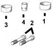
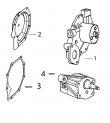
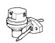
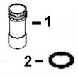
1 .. PACKING 1 X (ORDER RE504827)
2 .. PACKING 2 X (ORDER RE504827)
3 RE506868 FITTING 1 X (IN)
RE503796 FITTING 1 X (OUT)
4 R54025 WASHER 1 X
5 RE65265 HAND PRIMER 1 X
6 RE503803 FUEL PUMP 1 X
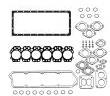
FUEL INJECTION SYSTEM
SECTIONAL INDEX
INDEX DE SECTION
GRUPPENINDEX
INDICE DELLA SEZIONE
INDICE DE SECCION
GRUPPSFORTECKNING
RGP7042 -UN-23SEP02
KEY PART NO. PART NAME QTY SERIAL NO. F F F REMARKS
1 RE47431 FUEL LINE 1 X NO. 6
2 RE47430 FUEL LINE 1 X NO. 5
3 RE47429 FUEL LINE 1 X NO. 4
4 R120185 BOLT 5 X
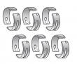
R58186 CLAMP 10 X
R120181 STRAP 5 X
R120182 STRAP 5 X
5 RE47428 FUEL LINE 1 X NO. 3
6 RE47427 FUEL LINE 1 -080424 X
RE502930 FUEL LINE 1 080425- X NO. 2, (SUB FOR RE47427)
7 RE47426 FUEL LINE 1 -080424 X
RE502929 FUEL LINE 1 080425- X NO. 1, (SUB FOR RE47426)
8 R120186 BOLT 2 X
R71212 CLAMP 1 X
R120183 STRAP 1 X
R120184 STRAP 1 X
R59297 HALF CLAMP 2 X
9 R59305 STRAP 1 X
R58186 CLAMP 1 X
R74030 CLAMP 1 X
R74804 CLAMP 1 X
R120186 BOLT 1 X
R120181 STRAP 1 X
R120182 STRAP 1 X
10 R120185 BOLT 1 X
R59297 HALF CLAMP 2 X
R120183 STRAP 2 X
11 RE55662 ABSORBER 1 X
12 24H1884 WASHER 1 X 13/32" X 13/16" X 0.120" 13/32" X
13/16" X 0.120"
13 19M7166 CAP SCREW 1 X M10 X 20 M10 X 20
14 RE61593 INJECTION NOZZLE 6 X (A) (ROBERT BOSCH)
R51603 O-RING 6 X
15 R84472 WASHER 6 X 7.360 X 18.160 X 2 MM (0.290" X 0.715"
X 0.079") 7.360 X 18.160 X 2 MM
(0.290" X 0.715" X 0.079")
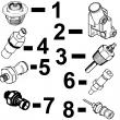
16 R504057 O-RING 6 087550- X
17 RE501970 ADAPTER 6 087550- X
18 R79604 TUBE NUT 6 087550- X
19 R51937 TUBE NUT 1 X
20 AR85519 PLUG 1 X
21 RE500803 FUEL LINE 1 087550- X
22 R77551 O-RING 6 -087549 X
23 R87082 FITTING 6 -087549 X
24 R79604 TUBE NUT 6 -087549 X
25 R79605 WASHER 6 -087549 X
26 R79606 TEE FITTING 6 -087549 X
27 R51936 SEALING WASHER 11 -087549 X
28 RE15807 FUEL LINE 2 -087549 X
29 RE15808 FUEL LINE 2 -087549 X
30 RE36421 FUEL LINE 2 -087549 X
31 R97061 TEE FITTING 1 -087549 X
(A) 1 ORANGE DOT
(1) POINT ORANGE
(1) ORANGEFARBENER PUNKT
(1) PUNTO ARANCIONE
(1) PUNTO ANARANJADO
(1) ORANGEFAERGAD PUNKT
KEY PART NO. PART NAME QTY SERIAL NO. F F F REMARKS
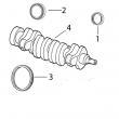
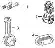
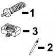
1 R60277 SNAP RING 1 X
2 R375R O-RING 1 X
3 R60279 NUT 1 X
4 R60278 SNAP RING 1 X
5 .. NOZZLE HOLDER 1 X (SUB RE61593)
6 R83720 WASHER 1 X 1.02 MM (.0402")
R83721 WASHER 1 X 1.08 MM (.0425")
R83722 WASHER 1 X 1.12 MM (.0441")
R83723 WASHER 1 X 1.18 MM (.0465")
R83724 WASHER 1 X 1.22 MM (.0480")
R83725 WASHER 1 X 1.28 MM (.0504")
R83726 WASHER 1 X 1.30 MM (.0512")
R83727 WASHER 1 X 1.38 MM (.0543")
R83728 WASHER 1 X 1.42 MM (.0559")
R83729 WASHER 1 X 1.48 MM (.0583")
R83730 WASHER 1 X 1.50 MM (.0591")
R83731 WASHER 1 X 1.58 MM (.0622")
R83732 WASHER 1 X 1.60 MM (.0630")
R83733 WASHER 1 X 1.68 MM (.0661")
R83734 WASHER 1 X 1.70 MM (.0669")
R83735 WASHER 1 X 1.78 MM (.0701")
R83736 WASHER 1 X 1.82 MM (.0717")
R83737 WASHER 1 X 1.88 MM (.0740")
R83738 WASHER 1 X 1.90 MM (.0748")
R83739 WASHER 1 X 1.98 MM (.0780")
7 R108699 SPRING 1 X
8 R108700 SEAT 1 X
9 R108701 PLATE 1 X
10 RE42306 INJECTION NOZZLE 1 X (7 X .240)
11 R127176 NUT 1 X
12 R84472 WASHER 1 X
13 RE61593 INJECTION NOZZLE 6 X (A) (ROBERT BOSCH)
(A) (1) ORANGE DOT
(1) POINT ORANGE
(1) ORANGEFARBENER PUNKT
(1) PUNTO ARANCIONE
(1) PUNTO ANARANJADO
(1) ORANGEFAERGAD PUNKT