配件详情
强鹿JOHNDEERE 高压油泵型号:
RE506965、RE53785、RE506879、RE506879、RE64241、RE503049、RE505052、SE501237、RE518089、RE506883、RE503051、RE508613、RE502711、SE501237、RE518164、SE501234、RE518167、RE501317、RE506085、RE506084、RE51866、SE501235、SE501234、RE505475、RE539769、RE518088、RE518166、RE503049
麦克福斯约翰迪尔发动机零配件
|
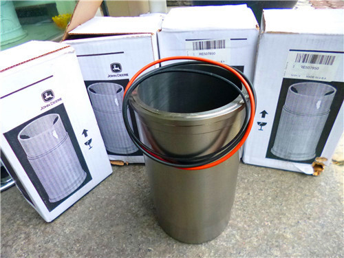
约翰迪尔 6068T/H 6.8T/H 活塞(米)RE515037 排放 2 & 3
|
|
|
|
|
|
发动机和设备型号
|
孔径:
4.19 in 106.5 mm
销径 Ø:
1.6250 in (+/- .0002) = 41mm
|
|
|
information&recommendations. ctm100 (20mar01) 01-002-7 powertech 10.5 l & 12.5 l diesel engines 032001 pn=35 fuels, lubricants&coolant 01 002 8 dpsg,ouod002,1824 –19–02aug00–1/1 oilscan?and coolscan? t6829ab –un–18oct88 t6828ab –un–15jun89 oilscan?and coolscan? are john deere sampling programs to help you monitor machine performance and identify potential problems before they cause serious damage. oil&coolant samples should be taken from each system prior to its recommended change interval. check with your john deere dealer for the availability of oilscan?&coolscan? kits. oilscan is a registered trademark of deere & company. coolscan is a registered trademark of deere & company. ctm100 (20mar01) 01-002-8 powertech 10.5 l & 12.5 l diesel engines 032001 pn=36 fuels, lubricants&coolant 01 002 9 dx,grea1 –19–24jan00–1/1 grease ts1667 –un–30jun99 grease use grease based on nlgi consistency numbers&the expected air temperature range during the service interval. the following greases are preferred: ? john deere sd polyurea grease the following greases are also recommended: ? john deere hd moly grease ? john deere hd lithium complex grease ? john deere hd water resistant grease ? john deere grease-gard other greases may be used if they meet the following: ? nlgi performance classification gc-lb important: some types of grease thickener are not compatible with others. consult your grease supplier before mixing different types of grease. ctm100 (20mar01) 01-002-9 powertech 10.5 l & 12.5 l diesel engines 032001 pn=37 fuels, lubricants&coolant 01 002 10 dx,cool3 –19–05feb99–1/1 diesel engine coolant the engine cooling system is filled to provide year-round protection against corrosion&cylinder liner pitting,&winter freeze protection to -37°c (-34°f). the following engine coolant is preferred for service: ? john deere cool-gard prediluted coolant the following engine coolant is also recommended: ? john deere cool-gard coolant concentrate in a 40 to 60% mixture of concentrate with quality water. other low silicate ethylene glycol base coolants for heavy-duty engines may be used if they meet one of the following specifications: ? astm d5345 (prediluted coolant) ? astm d4985 (coolant concentrate) in a 40 to 60% mixture of concentrate with quality water coolants meeting these specifications require use of supplemental coolant additives, formulated for heavy-duty diesel engines, for protection against corrosion&cylinder liner erosion&pitting. a 50% mixture of ethylene glycol engine coolant in water provides freeze protection to -37°c (-34°f). if protection at lower temperatures is required, consult your john deere dealer for recommendations. water quality is important to the performance of the cooling system. distilled, deionized,/demineralized water is recommended for mixing with ethylene glycol base engine coolant concentrate. important: do not use cooling system sealing additives/antifreeze that contains sealing additives. coolant drain intervals drain the factory fill engine coolant, flush the cooling system,&refill with new coolant after the first 3 years/3000 hours of operation. subsequent drain intervals are determined by the coolant used for service. at each interval, drain the coolant, flush the cooling system,&refill with new coolant. when john deere cool-gard is used, the drain interval may be extended to 5 years/5000 hours of operation, provided that the coolant is tested annually and additives are replenished, as needed, by adding a supplemental coolant additive. if cool-gard is not used, the drain interval is reduced to 2 years/2000 hours of operation. ctm100 (20mar01) 01-002-10 powertech 10.5 l & 12.5 l diesel engines 032001 pn=38 fuels, lubricants&coolant 01 002 11 dpsg,ouod002,1835 –19–03aug00–1/2 diesel engine coolants, supplemental additive information engine coolants are a combination of three chemical components: ethylene glycol (antifreeze), inhibiting coolant additives,&quality water. coolant specifications some products, including john deere john deere cool-gard prediluted coolant, are fully formulated coolants that contain all three components in their correct concentrations. do not add an initial charge of supplemental coolant additives to these fully formulated products. some coolant concentrates, including john deere cool-gard coolant concentrate, contain both ethylene glycol antifreeze&inhibiting coolant additives. mix these products&quality water, but do not add an initial charge of supplemental coolant additives. coolants meeting astm d5345 (prediluted coolant) or astm d4985 (coolant concentrate) require an initial charge of supplemental coolant additives. replenish coolant additives the concentration of coolant additives is gradually depleted during engine operation. periodic replenishment of inhibitors is required, even when john deere cool-gard is used. follow the recommendations in this manual for the use of supplemental coolant additives. why use supplemental coolant additives? operating without proper coolant additives will result in increased corrosion, cylinder liner erosion&pitting, and other damage to the engine&cooling system. a simple mixture of ethylene glycol&water will not give adequate protection. use of supplemental coolant additives reduces corrosion, erosion,&pitting. these chemicals reduce the number of vapor bubbles in the coolant and help form a protective film on cylinder liner surfaces. this film acts as a barrier against the harmful effects of collapsing vapor bubbles. avoid automotive-type coolants never use automotive-type coolants (such as those meeting astm d3306/astm d4656). these coolants do not contain the correct additives to protect heavy-duty diesel engines. they often contain a high concentration of silicates&may damage the engine or cooling system. non-aqueous propylene glycol non-aqueous propylene glycol should not be used with john deere diesel engines. this coolant works best with coolant temperatures above the acceptable engine operating range. this could decrease engine life due to lower engine oil viscosity. in addition, electronically controlled engines could experience premature power de-rate due to high coolant temperature. water quality water quality is important to the performance of the cooling system. distilled, deionized,/demineralized water is recommended for mixing with ethylene glycol base engine coolant concentrate. all water used in the cooling system should meet the following minimum specifications for quality: chlorides 40 mg/l/less sulfates 100 mg/l/less total dissolved solids 340 mg/l/less total hardness 170 mg/l/less ph level 5.5 to 9.0 freeze protection the relative concentrations of ethylene glycol and water in the engine coolant determine its freeze protection limit. refer to the chart on the following page. ctm100 (20mar01) 01-002-11 powertech 10.5 l & 12.5 l diesel engines 032001 pn=39 continued on next page fuels, lubricants&coolant 01 002 12 dpsg,ouod002,1835 –19–03aug00–2/2 ethylene glycol freeze protection limit 40% -24°c (-12°f) 50% -37°c (-34°f) 60% -52°c (-62°f) do not use a coolant-water mixture greater than 60% ethylene glycol. dx,cool9 –19–17feb99–1/1 testing diesel engine coolant maintaining adequate concentrations of glycol and inhibiting additives in the coolant is critical to protect the engine&cooling system against freezing, corrosion,&cylinder liner erosion&pitting. test the coolant solution at intervals of 12 months or less&whenever excessive coolant is lost through leaks/overheating. coolant test strips coolant test strips are available from your john deere dealer. these test strips provide a simple, effective method to check the freeze point&additive levels of your engine coolant. compare the results to the supplemental coolant additive (sca) chart to determine the amount of inhibiting additives in your coolant&whether more john deere coolant conditioner should be added. coolscan for a more thorough evaluation of your coolant, perform a coolscan analysis. see your john deere dealer for information about coolscan. ctm100 (20mar01) 01-002-12 powertech 10.5 l & 12.5 l diesel engines 032001 pn=40 fuels, lubricants&coolant 01 002 13 dx,cool4 –19–15jun00–1/1滨州约翰迪尔联合收割机发动机活塞厂家批发,白山强鹿发电机RE504836滤芯滤清器厂家供应,莱芜约翰迪尔强鹿柴油机R98062进气门代理商,临夏约翰迪尔传感器RE167207供应商,阿里强鹿柴油机凸轮轴齿哪里买,辽阳JohnDeere气缸垫RE55475多少钱,牡丹江强鹿启动机RE53186的价格,中山约翰迪尔拖拉机发动机全车线束找哪家,黄冈约翰迪尔挖掘机柴油机配件找哪家,梅州强鹿6068柴油机机油底壳垫片信息,铜陵约翰迪尔铰接自卸卡车柴油机配件哪家好,百色JohnDeere主轴瓦RE529319批发,潮州约翰迪尔联合收割机发动机电脑板哪家买,松原强鹿6081柴油发动机连杆批发商,四平JohnDeere气门导管R106831厂家供应,舟山强鹿6068柴油机水泵厂家批发,台北强鹿柴油机缸套阻水圈AR72351代理商,大同约翰迪尔柴油发电机组缸套找哪家,泰安约翰迪尔CH530甘蔗收获机发动机配件厂家价格,黄冈美国约翰迪尔输油泵一级代理,昌都强鹿发电机控制板RE251374供应商,湖北JohnDeere进气门R520223信息,徐州强鹿连杆螺丝TR501124哪家买,崇左JohnDeere连杆铜衬套R74008诚信推荐,吕梁约翰迪尔挖掘机进排气门价格,克孜勒苏强鹿柴油发动机3029气缸垫供货商,台中强鹿柴油发电机组涡轮增压器信息,钦州JohnDeere连杆RE535555批发商,临夏JohnDeere曲轴齿轮R104587找哪家,黄石约翰迪尔曲轴RE534314多少钱,扬州强鹿6068柴油机喷油器O型圈诚信推荐,长沙强鹿滤芯滤清器RT6005011112哪家买,丹东约翰迪尔6068柴油机气门室盖垫片批发商,揭阳JohnDeere活塞销R502755批发价,白山约翰迪尔空气加热器TRE502668价格,中山强鹿6081柴油发动机水泵O型圈供货商,鄂尔多斯强鹿柴油机曲轴RE505921批发商,松原JOHNDERE四配套哪家买,衡阳强鹿R26125气门弹簧信息,甘南JohnDeere挺铜柱RE540586厂家批发, supplemental coolant additives the concentration of coolant additives is gradually depleted during engine operation. for all recommended coolants, replenish additives between drain intervals by adding a supplemental coolant additive every 12 months/as determined necessary by coolant testing. john deere coolant conditioner is recommended as a supplemental coolant additive in john deere engines. important: do not add a supplemental coolant additive when the cooling system is drained&refilled with john deere cool-gard. if other coolants are used, consult the coolant supplier and follow the manufacturer’s recommendation for use of supplemental coolant additives. the use of non-recommended supplemental coolant additives may result in additive drop-out&gelation of the coolant. add the manufacturer’s recommended concentration of supplemental coolant additive. do not add more than the recommended amount. ctm100 (20mar01) 01-002-13 powertech 10.5 l & 12.5 l diesel engines 032001 pn=41 fuels, lubricants&coolant 01 002 14 rg,01,dt7035 –19–14nov00–1/2 replenishing supplemental coolant additives (scas) between coolant changes rg6261 –un–08dec97 radiator coolant check rg6262 –un–05dec97 jt07298 refractometer important: do not add supplemental coolant additives when the cooling system is drained&refilled with john deere antifreeze/summer coolant or john deere cool-gard?. note: if a system is to be filled with coolant that does not contain scas, the coolant must be precharged. determine the total system capacity&premix with 3% john deere coolant conditioner. through time&use, the concentration of coolant additives is gradually depleted during engine operation. periodic replenishment of inhibitors is required, even when john deere六盘水JohnDeere平衡轴铜套TR115299代理,榆林强鹿RE501578修理包公司,湛江JohnDeere传感器RE52722代理商,巴中强鹿皮带张紧轮RE68715的价格,昭通约翰迪尔强鹿4045活塞供应商,郑州约翰迪尔强鹿7930拖拉机RE541925油水分离燃油滤清器厂家价格,太原强鹿柴油发电机组进排气门供货商,文山约翰迪尔温度传感器R501130厂家供应,枣庄强鹿RE500608连杆组件哪里买,保山强鹿3029R91889气门锁夹厂家批发,日喀则强鹿6068柴油机温度传感器找哪家,曲靖强鹿6090柴油发动机风扇张紧轮代理商,张家界约翰迪尔3029DF128机体信息,大理约翰迪尔发动机连杆总成多少钱,丽水约翰迪尔1000拖拉机发动机配件厂家供应,哈尔滨强鹿柴油机启动马达RE515843代理商,丹东美国强鹿发电机大修包供应商,吉安JohnDeereel36936喷油器哪家买,宝鸡强鹿JOHNDEERE柴油发动机原厂活塞环哪家买,六盘水强鹿柴油机加大连杆瓦RE65909批发价,香港岛约翰迪尔装载机发动机主线束哪家买,六安JohnDeere电热塞厂家供应,佛山约翰迪尔发动机继电器厂家批发,丽水约翰迪尔4039连杆R80032市场报价,丽江强鹿柴油发动机3029修理包市场报价,汕尾强鹿柴油机发电机RE500227供应商, antifreeze/summer coolant is used. the cooling system must be recharged with additional supplemental coolant additives available in the form of liquid coolant conditioner. maintaining the correct coolant conditioner concentration (scas)&freeze point is essential in your cooling system to protect against rust, liner pitting and corrosion,&freeze-ups due to incorrect coolant dilution. john deere liquid coolant conditioner is recommended as a supplemental coolant additive in john deere engines. do not mix one brand of sca with a different brand. test the coolant solution at 600 hours/12 months of operation using either john deere coolant test strips or a coolscan? analysis. if a coolscan? analysis is not available, recharge system per instructions printed on label of john deere liquid coolant conditioner. cool-gard is a registered trademark of deere & company coolscan is a registered trademark of deere & company. continued on next page ctm100 (20mar01) 01-002-14 powertech 10.5 l & 12.5 l diesel engines 032001 pn=42 fuels, lubricants&coolant 01 002 15 rg,01,dt7035 –19–14nov00–2/2 important: always maintain coolant at correct level&concentration. do not operate engine without coolant for even a few minutes. if frequent coolant makeup is required, the glycol concentration should be checked with jt07298 coolant/battery tester to ensure that the desired freeze point is maintained. follow manufacturer’s instructions provided with refractometer. add the manufacturer’s recommended concentration of supplemental coolant additive. do not add more than the recommended amount. the use of non-recommended supplemental coolant additives may result in additive drop-out&gelation of the coolant. if other coolants are used, consult the coolant supplier and follow the manufacturer’s recommendation for use of supplemental coolant additives. see diesel engine coolants and supplemental additive information earlier in this group for proper mixing of coolant ingredients before adding to the cooling system. dx,cool6 –19–18mar96–1/1 operating in warm temperature climates john deere engines are designed to operate using glycol base engine coolants. always use a recommended glycol base engine coolant, even when operating in geographical areas where freeze protection is not required. important: water may be used as coolant in emergency situations only. foaming, hot surface aluminum and iron corrosion, scaling,&cavitation will occur when water is used as the coolant, even when coolant conditioners are added. drain cooling system&refill with recommended glycol base engine coolant as soon as possible. ctm100 (20mar01) 01-002-15 powertech 10.5 l & 12.5 l diesel engines 032001 pn=43 fuels, lubricants&coolant 01 002 16 rg,01,dt7033 –19–29oct97–1/2 flush&service cooling system ts281 –un–23aug88 caution: explosive release of fluids from pressurized cooling system can cause serious burns. shut off engine. only remove filler cap when cool enough to touch with bare hands. slowly loosen cap to first stop to relieve pressure before removing cap completely. important: air must be expelled from cooling system when system is refilled. follow procedure given in your operator’s manual. the ethylene glycol base (antifreeze) can become depleted of scas allowing various acids to form that will damage engine components. in addition, heavy metals, such as lead, copper&zinc, accumulate in the ethylene glycol base. the heavy metals come from corrosion that occurs to some degree with in a cooling system. when a coolant is saturated to the point where it can no longer hold heavy metals&other dissolved solids, they settle out&act as abrasives on engine parts. note: refer to your operator’s manual for a specific service interval. flush cooling system as described in your operator’s manual. clean cooling system with clean water and ty15979 john deere heavy-duty cooling system cleaner/an equivalent cleaner such as fleetguard? restore?or restore plus?. follow the instructions provided with the cleaner. refill cooling system with the appropriate coolant solution. see engine coolant specifications, earlier in this group. fleetguard is a registered trademark of the cummins engine company. restore is a trademark of fleetguard. restore plus is a trademark of fleetguard. continued on next page ctm100 (20mar01) 01-002-16 powertech 10.5 l & 12.5 l diesel engines 032001 pn=44 fuels, lubricants&coolant 01 002 17 rg,01,dt7033 –19–29oct97–2/2 important: never overfill the system. a pressurized system needs space for heat expansion without overflowing at the top of the radiator. coolant level should be at bottom of radiator filler neck. air must be expelled from cooling system when system is refilled. loosen plug in side of thermostat housing to allow air to escape when filling system. retighten plug when all the air has been expelled. after adding new coolant solution, run engine until it reaches operating temperature. this mixes the coolant solution uniformly&circulates it through the entire system. after running engine, check coolant level and entire cooling system for leaks. contact your engine servicing dealer, if there are further questions. rg,01,dt7032 –19–29oct97–1/1 disposing of coolant ts1133 –un–26nov90 improperly disposing of engine coolant can threaten the environment&ecology. use leakproof containers when draining fluids. do not use food/beverage containers that may mislead someone into drinking from them. do not pour waste onto the ground, down a drain,/into any water source. inquire on the proper way to recycle/dispose of waste from your local environmental/recycling center,/from your engine servicing dealer. ctm100 (20mar01) 01-002-17 powertech 10.5 l & 12.5 l diesel engines 032001 pn=45 fuels, lubricants&coolant 01 002 18 ctm100 (20mar01) 01-002-18 powertech 10.5 l & 12.5 l diesel engines 032001 pn=46 section 02 repair&adjustments contents 02 page page group 010—engine rebuild guide, break-in&remove valve assembly 02-020-24 tune-up inspect&measure valve springs 02-020-25 engine overhaul guidelines 02-010-1 inspect valve rotators 02-020-26 engine repair stand 02-010-1 clean, inspect,&measure valves 02-020-27 safety precautions 02-010-2 grind valves .02-020-28 disconnect turbocharger oil inlet line 02-010-3 clean&inspect cylinder head 02-020-29 install engine adapter onto repair stand 02-010-3 check cylinder head flatness 02-020-30 engine lifting procedure 02-010-4 measure cylinder head thickness 02-020-31 mount engine onto repair stand 02-010-5 resurface cylinder head combustion clean engine .02-010-7 face 02-020-32 6105&6125 engine disassembly measure valve guide id 02-020-33 sequence 02-010-8 replace valve guides 02-020-33 sealant application guidelines 02-010-11 clean&inspect valve seats 02-020-34 6105&6125 engine assembly grind valve seats 02-020-35 sequence .02-010-13 remove valve seat inserts 02-020-36 engine break-in guidelines 02-010-15 measure valve seat bore in cylinder perform engine break-in 02-010-16 head 02-020-37 check crankcase ventilation system 02-010-17 install valve seat inserts 02-020-38 check air intake system 02-010-18 install valves .02-020-38 check exhaust system 02-010-18 replace unit injector sleeve in cylinder check&service cooling system 02-010-19 head using jdg981 02-020-40 check electrical system 02-010-21 replace unit injector sleeve in cylinder preliminary engine testing before head using jdg1184 02-020-45 tune-up 02-010-22 clean&inspect top deck of cylinder general tune-up recommendations 02-010-23 block 02-020-55 measure cylinder liner standout (height group 020—cylinder head&valves above block) 02-020-56 remove&install rocker arm cover 02-020-1 install cylinder head 02-020-57 clean&inspect crankcase ventilation torque-turn cylinder head cap screws 02-020-59 assembly 02-020-2 install rocker arm assembly 02-020-61 replace rocker arm cover gasket 02-020-3 complete final assembly for cylinder head check&adjust valve assembly installation .02-020-68 clearances&injector preload 02-020-4 remove rocker arm assembly 02-020-10 group 030—cylinder block, liners, pistons, and remove cylinder head 02-020-12 rods diagnosing head gasket joint failures 02-020-17 front plate-to-cylinder block torque head gasket inspection&repair sequence 02-030-1 sequence .02-020-19 remove&install cylinder block front disassemble&inspect rocker arms&plate 02-030-2 shaft assembly 02-020-21 preliminary liner, piston,&rod checks 02-030-6 preliminary cylinder head&valve connecting rods—general information 02-030-7 checks 02-020-22 remove pistons&connecting rods 02-030-8 assemble rocker arms&shaft measure cylinder liner standout (height assembly 02-020-23 above block) 02-030-12 check valve height in relation to head surface (valve recess) 02-020-23 continued on next page ctm100 (20mar01) 02-1 powertech 10.5 l & 12.5 l diesel engines 032001 pn=1 contents page page remove cylinder liners using d01062aa rear seal torque sequence 02-040-3 or d01073aa cylinder liner puller 02-030-13 flywheel torque sequence 02-040-3 remove cylinder liners using jdg1145 crankshaft vibration damper torque cylinder liner service set 02-030-15 sequence 02-040-4 visually inspect cylinder liners 02-030-17 inspect crankshaft vibration damper 02-040-5 deglaze cylinder liners 02-030-18 check crankshaft end play 02-040-6 02 clean cylinder liners 02-030-19 remove crankshaft vibration damper and cylinder liner manufacturing date code pulley 02-040-7 explanation 02-030-20 remove crankshaft front oil seal 02-040-8 disassemble piston/rod assembly&clean remove timing gear cover 02-040-9 piston 02-030-21 check flywheel housing face runout 02-040-10 check piston compression ring groove check flywheel face flatness 02-040-11 wear—6105 engines 02-030-23 remove flywheel 02-040-11 check piston compression ring groove inspect&repair flywheel 02-040-12 wear—6125 engines 02-030-24 replace flywheel ring gear 02-040-13 check piston oil control ring groove remove&install flywheel housing 02-040-14 wear—6105&6125 engines 02-030-25 install flywheel 02-040-15 inspect piston pin&pin bore in piston 02-030-26 remove rear crankshaft oil seal and determine piston-to-liner clearance 02-030-27 housing assembly 02-040-16 measure liner flange thickness 02-030-29 crankshaft&main bearing failure inspect&measure connecting rod analysis 02-040-18 bearings 02-030-30 remove crankshaft main bearings 02-040-19 inspect connecting rod&cap 02-030-32 check main bearing-to-journal oil inspect piston pins&rod bushings 02-030-35 clearance .02-040-21 remove piston pin bushing, clean,&remove crankshaft 02-040-22 inspect bushing bore 02-030-37 inspect crankshaft 02-040-23 install piston pin bushing 02-030-38 measure assembled id of bearings and complete disassembly of cylinder block (if od of crankshaft journals 02-040-25 required) 02-030-39 measure assembled id of main bearing inspect&clean cylinder block 02-030-40 caps (without bearings) 02-040-26 measure cylinder block 02-030-42 crankshaft grinding guidelines 02-040-27 recheck cylinder liner standout (height crankshaft grinding specifications 02-040-28 above block) 02-030-44 replace crankshaft drive gear 02-040-29 install cylinder liner o-rings&inspect thrust bearings 02-040-30 packings 02-030-45 thrust bearing new part specifications 02-040-30 install cylinder liners 02-030-46 install main bearing inserts in block 02-040-31 assemble pistons&connecting rods 02-030-48 install crankshaft 02-040-32 install pistons&connecting rods 02-030-49 install crankshaft rear oil seal housing 02-040-35 torque-turn connecting rod cap install crankshaft rear oil seal&wear screws 02-030-53 sleeve assembly 02-040-36 check engine rotation for excessive install timing gear cover 02-040-37 tightness 02-030-54 install crankshaft vibration damper and measure piston protrusion 02-030-54 front oil seal 02-040-42 remove&install piston spray jets 02-030-55 complete final assembly 02-040-46 complete final assembly 02-030-56 group 050—camshaft&timing gear train group 040—crankshaft, main bearings,&camshaft gear retainer torque sequence 02-050-1 flywheel camshaft gear access cover torque timing gear cover torque sequence 02-040-1 sequence 02-050-1 camshaft gear access cover torque check&adjust camshaft-to-crankshaft sequence 02-040-1 timing 02-050-2 front seal torque sequence 02-040-2 rear seal housing torque sequence 02-040-2 continued on next page ctm100 (20mar01) 02-2 powertech 10.5 l & 12.5 l diesel engines 032001 pn=2 contents page page adjust front timing gear backlash 02-050-4 install thermostats 02-070-11 remove&install camshaft 02-050-8 test thermostat opening temperature 02-070-12 replace fuel supply pump drive pin 02-050-17 remove&install thermostat housing 02-070-13 02 visually inspect camshaft&roller remove&install coolant heater—if followers 02-050-17 equipped 02-070-14 inspect&measure camshaft bushing id&journal od 02-050-18 group 080—air intake&exhaust system measure camshaft lobe lift height 02-050-19 extending turbocharger life 02-080-1 inspect camshaft position sen lobe 02-050-19 remove turbocharger 02-080-3 replace camshaft bushings 02-050-20 turbocharger failure analysis 02-080-4 sae “a” (front)&sae “b” (rear) auxiliary turbocharger seven-step inspection 02-080-6 drive assembly 02-050-25 perform radial bearing clearance test 02-080-13 sae “b” rear auxiliary drive 02-050-26 perform axial bearing end play test 02-080-14 align sae “a” front auxiliary drive repair turbocharger 02-080-14 adapter 02-050-27 prelube turbocharger 02-080-15 install turbocharger 02-080-16 group 060—lubrication system turbocharger break-in 02-080-17 oil filter&valve housing torque remove, inspect,&install exhaust sequence 02-060-1 manifold 02-080-18 oil pan torque sequence 02-060-2 remove, inspect,&install intake oil filter&oil conditioning housing manifold 02-080-21 assembly 02-060-3 remove&install aftercooler assembly remove oil filter&valve housing/oil (6105a&6125a engines) 02-080-23 cooler cover&valve housing 02-060-4 inspect&repair aftercooler (6105a and inspect&replace oil filter adapter 02-060-4 6125a engines) 02-080-25 remove, inspect,&install oil pressure regulating valve 02-060-5 group 090—fuel system remove, inspect,&install oil cooler fuel system 02-090-1 and oil filter bypass valves 02-060-6 remove, inspect,&install oil pressure group 100—starting&charging systems relief valve (if equipped) 02-060-7 remove&install alternator (oem remove, clean,&inspect engine oil engines) 02-100-1 cooler 02-060-8 remove&install starter motor (oem install oil cooler/oil filter valve housing engines) 02-100-2 assembly/oil cooler cover/valve housing assembly 02-060-10 remove engine oil pump 02-060-12 clean&inspect oil pump&drive gear 02-060-13 install engine oil pump 02-060-14 remove engine oil pan 02-060-15 remove&install oil pickup tube 02-060-16 install engine oil pan 02-060-17 group 070—cooling system replace bearings in fan drive assembly 02-070-1 inspect&check belt tensioner spring tension 02-070-4 replace belt tensioner assembly 02-070-6 remove coolant pump 02-070-7 clean&inspect coolant pump parts 02-070-8 install coolant pump 02-070-9 remove thermostats 02-070-10 ctm100 (20mar01) 02-3 powertech 10.5 l & 12.5 l diesel engines 032001 pn=3 contents 02 ctm100 (20mar01) 02-4 powertech 10.5 l & 12.5 l diesel engines 032001 pn=4 group 010 engine rebuild guide, break-in&tune-up 02 010 1 dpsg,ouo1032,3410 –19–15jun00–1/1 engine overhaul guidelines engine life&performance will vary depending on operating conditions&the level of regular engine maintenance. engines can be brought back to original performance standards through proper overhaul procedure and replacement of parts with genuine john deere service parts. overhauling the engine prior to failure can avoid costly repairs&downtime. consider installing a john deere overhaul kit when: ? the engine begins to experience power loss&there are no known engine component failures. ? the engine is hard to start due to low cranking compression. ? the engine begins to smoke&there are no known engine component failures. ? the engine begins to use oil. refer to section 04 for acceptable oil consumption. ? the engine has high usage hours&the owner wants to take preventive measure to avoid high-cost repairs and costly downtime. john deere overhaul kits have a 1500-hour/12-month warranty, whichever comes first. installation labor is covered by warranty if an authorized john deere dealer installed the overhaul kit&the replacement parts. rg,rg34710,1043 –19–23oct97–1/1 engine repair stand rg4929 –un–05dec97 engine repair stand a—engine repair stand note: only the 2722 kg (6000 lb) heavy-duty engine repair stand (a) no. d05223st manufactured by owatonna tool co., owatonna, minnesota is referenced in this manual. when any other repair stand is used, consult the manufacturer’s instructions for mounting the engine. refer to machine technical manual for steps to remove engine from machine before installing it on repair stand. ctm100 (20mar01) 02-010-1 powertech 10.5 l & 12.5 l diesel engines 032001 pn=49 engine rebuild guide, break-in&tune-up 02 010 2 rg,rg34710,45 –19–30sep97–1/1 safety precautions the engine repair stand should be used only by qualified service technicians familiar with this equipment. to maintain shear strength specifications, alloy steel class 12.9/sae grade 8/higher cap screws must be used to mount adapters&engine to repair stand. use loctite? 242 thread lock&sealer on cap screws when installing lifting straps on engine. tighten cap screws to specifications given. for full thread engagement, be certain that tapped holes in adapters&engine blocks are clean? damaged. a thread length engagement equal to 1-1/2 screw diameters minimum is required to maintain strength requirements. to avoid structural/personal injury, do not exceed the maximum capacity rating of 2722 kg (6000 lb). maximum capacity is determined with the center of the engine located not more than 330 mm (13 in.) from the mounting hub surface of the engine stand. the center of balance of an engine must be located within 51 mm (2 in.) of the engine stand rotating shaft. engine center of balance is generally located a few millimeters above the crankshaft. to prevent possible personal injury due to engine slippage, recheck to make sure engine is solidly mounted before releasing support from engine lifting device. never permit any part of the body to be positioned under a load being lifted/suspended. accidental slippage may result in personal injury. the lifting jack is to be used when it is necessary to lift the engine for rotation. when working on the engine, the jack should be at its lowest position to keep the center of gravity&the possibility of tipping low. to prevent possible personal injury due to sudden engine movement, lower the engine by operating jack release valve slowly. do not unscrew release valve knob more than two turns from its closed position. loctite is a registered trademark of loctite corp. ctm100 (20mar01) 02-010-2 powertech 10.5 l & 12.5 l diesel engines 032001 pn=50 engine rebuild guide, break-in&tune-up 02 010 3 dpsg,ouo1004,918 –19–30jun99–1/1 disconnect turbocharger oil inlet line rg10241 –un–09jul99 turbocharger oil inlet line a—turbocharger oil inlet line 1. drain all engine oil&coolant, if not previously done. important: when servicing turbocharged engines on a rollover stand, disconnect turbocharger oil inlet line (a) from oil filter housing/turbocharger before rolling engine over. failure to do so may cause a hydraulic lock upon starting engine. hydraulic lock may cause possible engine failure. hydraulic lock occurs when trapped oil in the oil filter housing drains through the turbocharger, the exhaust and intake manifolds,&then into the cylinder head. after starting the engine, the trapped oil in the manifold&head is released into the 扬州迪尔柴油机大修包价格,喀什强鹿柴油发电机组电磁阀一级代理,乌海JohnDeere传感器RE522794厂家供应,株洲美国JohnDeere曲轴后油封RE53687信息,湖州JohnDeere机油底壳垫片R520844批发价,乐山强鹿RE561742量油尺、厂家供货,南京强鹿柴油机输油泵的价格,松原JOHNDERE四配套诚信推荐,遵义约翰迪尔?Johndeere活塞组件?RE61467哪家买,cylinder(s) filling them with oil causing hydraulic lock&possible engine failure. 2. disconnect turbocharger oil inlet line at turbocharger or oil filter base. rg,rg34710,46 –19–07nov00–1/1 install engine adapter onto repair stand rg8183 –un–08dec97 d05223st repair stand with 205466 adapter attach the no. 205466 adapter assembly (a) to engine repair stand using four 5/8-11 x 2 in. sae grade 8 (or higher grade) cap screws. tighten cap screws to specifications. specification engine adapter cap screws— torque . 135 n?m (100 lb-ft) ctm100 (20mar01) 02-010-3 powertech 10.5 l & 12.5 l diesel engines 032001 pn=51 engine rebuild guide, break-in&tune-up 02 010 4 rg,rg34710,47 –19–30jun99–1/2 engine lifting procedure rg10349 –un–13oct99 engine lift points rg10350 –un–13oct99 engine lifting a—alternator b—front plate lift eye c—exhaust shield d—jdg23 lift sling e—r128000 rear lift strap1 f—r128001 front lift strap1 caution: the only approved method for lifting the 6105&6125 engine is with the use of jdg23 lifting sling (d), r128000 rear lift strap (e)&r128001 front lift strap (f). the front plate lift eye (b) can be used as a lifting point instead of r128001 front lift strap. use extreme caution when lifting&never permit any part of the body to be positioned under an engine being lifted/suspended. lift engine with longitudinal loading on lift sling and lifting brackets only. angular loading greatly reduces lifting capacity of sling and brackets. important: ensure that engine lifting straps are secured with class 12.9 (or higher class) cap screws. apply ty9370 loctite? 242 thread lock&sealer to lift strap cap screws. note: if lift eye in front plate (b) is used instead of r128001 front lift strap, remove alternator (a). if front lift strap (f) is being used, remove exhaust shield (c)&install lift strap using shield mounting cap screw holes. 1. install r128001 front lift strap&r128000 rear lift strap (or attach sling to front plate lift eye)&tighten cap screws to specifications. specification engine lift strap cap screws— torque . 90 n?m (66 lb-ft) note: lift spacing on sling is adjustable. position each lifting point so that engine hangs level when lifted. 2. attach the jdg23 engine lifting sling (d) to lift straps and overhead hoist/floor crane of adequate lifting capacity. loctite is a registered trademark of loctite corp. 1 can be ordered from parts catalog. ctm100 (20mar01) 02-010-4 powertech 10.5 l & 12.5 l diesel engines 032001 pn=52 continued on next page engine rebuild guide, break-in&tune-up 02 010 5 rg,rg34710,47 –19–30jun99–2/2 important: lifting straps are designed to lift the engine&small acces ies such as hydraulic pumps&air compres s mounted to the engine auxiliary gear drive,/belt-driven components, such as air conditioning compres s and alternators. if larger components, such as pto’s, transmissions, generators or air compres s, are attached to other locations on the engine, the lift straps provided with the engine are not intended for this purpose. technician is responsible for providing adequate lifting devices under these situations. see machine technical manual for additional information on removing engine from machine. 3. carefully lift engine to desired location. rg,rg34710,48 –19–07nov00–1/3 mount engine onto repair stand rg8184a –un–05dec97 component removal for repair stand mounting a—starter motor b—primary fuel filter caution: never remove the overhead lifting equipment until the engine is securely mounted onto the repair stand&all mounting hardware is tightened to specified torque. always release the overhead lifting equipment slowly. 1. remove starter motor (a). 2. on engines with primary fuel filter/water separator (b) on left side of engine, remove primary fuel filter/water separator. on later engines with large single fuel filter mounted on left side of engine, remove fuel filter assembly. ctm100 (20mar01) 02-010-5 powertech 10.5 l & 12.5 l diesel engines 032001 pn=53 continued on next page engine rebuild guide, break-in&tune-up 02 010 6 rg,rg34710,48 –19–07nov00–2/3 rg8185 –un–05dec97 front repair stand cap screws a—cap screws important: do not use shorter cap screws than recommended since mounting threads in block bore may be stripped when tightening to specified torque. use only jdg980 metric bolt kit for mounting engine to repair stand. 3. mount engine to front engine adapter using two1 m16 x 2.0 x 65 mm (class 12.9) cap screws (a). tighten cap screws to specifications. specification engine-to-stand adapter cap screws—torque 400 n?m (300 lb-ft) 1 from jdg980 metric bolt kit. rg,rg34710,48 –19–07nov00–3/3 rg8186 –un–05dec97 rear repair stand cap screws b—cap screws 4. mount engine to rear engine adapter using two1 m16 x 2.0 x 65 mm (class 12.9) cap screws (b). tighten cap screws to specifications. specification engine-to-stand adapter cap screws—torque 400 n?m (300 lb-ft) 1 from jdg980 metric bolt kit. ctm100 (20mar01) 02-010-6 powertech 10.5 l & 12.5 l diesel engines 032001 pn=54 engine rebuild guide, break-in&tune-up 02 010 7 rg,rg34710,49 –19–21dec00–1/1 clean engine rg8188 –un–21may98 6125hrw engine on repair stand 1. cap/plug all openings (air intake, exhaust, fuel, coolant, etc.). 2. remove electrical components (starter, alternator, etc.). cover electrical components that are not removed with plastic&tape securely to prevent moisture damage. 3. thoroughly steam clean engine. important: never steam clean/pour cold water on an engine while it is still hot. to do so may cause seizure of precision parts. ctm100 (20mar01) 02-010-7 powertech 10.5 l & 12.5 l diesel engines 032001 pn=55 engine rebuild guide, break-in&tune-up 02 010 8 rg,rg34710,50 –19–16oct00–1/3 6105&6125 engine disassembly sequence the following sequence is suggested when complete engine disassembly for overhaul is required. refer to the appropriate repair group when removing individual components. note: remove starter motor&primary fuel filter/water separator before mounting engine onto repair stand. engine disassembly sequence procedure reference drain all coolant, fuel&engine oil. see disposing of coolant, section 01, group 002. perform john deere coolscan?&oilscan? analysis. dispose see oilscan&coolscan in section 01, group 002. of remaining fluids properly. see testing diesel engine coolant, section 01, group 002. remove starter motor. see
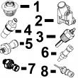
KEY PART NO. PART NAME QTY SERIAL NO. F F F REMARKS
1 RE57151 FUEL LINE 1 X X NO. 6
2 RE57150 FUEL LINE 1 X X NO. 5
3 RE57149 FUEL LINE 1 X X NO. 4
4 R71398 SCREW 5 X X
R58186 CLAMP 10 X X
R59305 STRAP 5 X X
R61144 STRAP 5 X X
R74030 CLAMP 1 X X
5 RE57148 FUEL LINE 1 X X NO. 3
6 RE57147 FUEL LINE 1 -081549 X X NO. 2
RE502933 FUEL LINE 1 081550- X X NO. 2
7 RE57146 FUEL LINE 1 -081549 X X NO. 1
RE502932 FUEL LINE 1 081550- X X NO. 1
8 21H1463 CAP SCREW 2 X X 0.190" X 7/8"
R59298 STRAP 1 X X
R61145 STRAP 1 X X
R120184 STRAP 1 X X
R59297 HALF CLAMP 2 X X
9 R59298 STRAP 1 X X
R58186 CLAMP 1 X X
R71212 CLAMP 1 X X
R74804 CLAMP 1 X X
R71398 SCREW 1 X X
R61145 STRAP 1 X X
R120182 STRAP 1 X X
10 21H1463 CAP SCREW 1 X X 0.190" X 7/8"
R59297 HALF CLAMP 2 X X
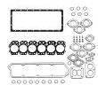
R59598 GASKET 2 X X
11 RE55662 ABSORBER 1 X X
12 24H1884 WASHER 1 X X 13/32" X 13/16" X 0.120" 13/32" X
13/16" X 0.120", (NLR)
13 19M7166 CAP SCREW 1 X X M10 X 20 M10 X 20
14 RE61593 INJECTION NOZZLE 6 X X (A) (ROBERT BOSCH)
R51603 O-RING 6 X X
15 R84472 WASHER 6 X X 7.360 X 18.160 X 2 MM (0.290" X 0.715"
X 0.079") 7.360 X 18.160 X 2 MM
(0.290" X 0.715" X 0.079")
16 R504057 O-RING 6 087550- X X
17 RE501970 ADAPTER 6 087550- X X
18 R79604 TUBE NUT 6 087550- X X
19 R51937 TUBE NUT 1 X X
20 AR85519 PLUG 1 X X
21 RE500803 FUEL LINE 1 087550- X X
22 R77551 O-RING 6 -087549 X X
23 R87082 FITTING 6 -087549 X X
24 R79604 TUBE NUT 6 -087549 X X
25 R79605 WASHER 6 -087549 X X
26 R79606 TEE FITTING 6 -087549 X X
27 R51936 SEALING WASHER 11 -087549 X X
28 RE15807 FUEL LINE 2 -087549 X X
29 RE15808 FUEL LINE 2 -087549 X X
30 RE36421 FUEL LINE 2 -087549 X X
31 R97061 TEE FITTING 1 -087549 X X
(A) 1 ORANGE DOT
(1) POINT ORANGE
(1) ORANGEFARBENER PUNKT
(1) PUNTO ARANCIONE
(1) PUNTO ANARANJADO
(1) ORANGEFAERGAD PUNKT
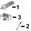
KEY PART NO. PART NAME QTY SERIAL NO. F F F REMARKS
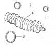
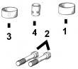
1 R60277 SNAP RING 1 X X
2 R375R O-RING 1 X X
3 R60279 NUT 1 X X
4 R60278 SNAP RING 1 X X
5 .. NOZZLE HOLDER 1 X X (SUB RE61593)
6 R83720 WASHER 1 X X 1.02 MM (.0402")
R83721 WASHER 1 X X 1.08 MM (.0425")
R83722 WASHER 1 X X 1.12 MM (.0441")
R83723 WASHER 1 X X 1.18 MM (.0465")
R83724 WASHER 1 X X 1.22 MM (.0480")
R83725 WASHER 1 X X 1.28 MM (.0504")
R83726 WASHER 1 X X 1.30 MM (.0512")
R83727 WASHER 1 X X 1.38 MM (.0543")
R83728 WASHER 1 X X 1.42 MM (.0559")
R83729 WASHER 1 X X 1.48 MM (.0583")
R83730 WASHER 1 X X 1.50 MM (.0591")
R83731 WASHER 1 X X 1.58 MM (.0622")
R83732 WASHER 1 X X 1.60 MM (.0630")
R83733 WASHER 1 X X 1.68 MM (.0661")
R83734 WASHER 1 X X 1.70 MM (.0669")
R83735 WASHER 1 X X 1.78 MM (.0701")
R83736 WASHER 1 X X 1.82 MM (.0717")
R83737 WASHER 1 X X 1.88 MM (.0740")
R83738 WASHER 1 X X 1.90 MM (.0748")
R83739 WASHER 1 X X 1.98 MM (.0780")
7 R108699 SPRING 1 X X
8 R108700 SEAT 1 X X
9 R108701 PLATE 1 X X
10 RE42306 INJECTION NOZZLE 1 X X (7 X .240)
11 R127176 NUT 1 X X
12 R84472 WASHER 1 X X
13 RE61593 INJECTION NOZZLE 6 X X (A) (ROBERT BOSCH)
(A) (1) ORANGE DOT
(1) POINT ORANGE
(1) ORANGEFARBENER PUNKT
(1) PUNTO ARANCIONE
(1) PUNTO ANARANJADO
(1) ORANGEFAERGAD PUNKT
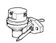
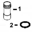
KEY PART NO. PART NAME QTY SERIAL NO. F F F REMARKS
1 R51936 SEALING WASHER 2 X
2 RE49589 FUEL LINE 1 -087549 X
RE501218 FUEL LINE 1 087550-090585 X (SUB RE504748)
RE504748 FUEL LINE 1 090586- X
R83490 FITTING 1 X
3 R76358 O-RING 1 X
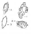
4 R121195 CAP SCREW 4 X (SUB FOR R112975)
5 R121164 GEAR 1 X
6 R67364 ELBOW FITTING 1 -087549 X
RE502650 FITTING 1 087550- X
R79060 O-RING 1 087550- X
7 R114130 STUD 4 X (SUB FOR R55396, THIS APPLICATION)
8 M72490 WASHER 4 X
9 14H1090 NUT 4 X (SUB FOR R55662, THIS APPLICATION)
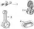
10 RE46375 FUEL PUMP 1 X (ROBERT BOSCH)
11 R79060 O-RING 1 X (SUB FOR R73858)
12 AR88903 ELBOW FITTING 1 X
13 R67264 PACKING 2 X
14 RE509065 OIL LINE 1 X (SUB FOR RE60577)
15 T18012 ELBOW FITTING 1 X
16 RE64214 FUEL INJECTION PUMP 1 X (A) (ROBERT BOSCH) (ALSO ORDER R504886
AND (2) 19M8826)
.. RE71255 PIPE PLUG 2 X
(A) "SEE YOUR AUTHORIZED PUMP REPAIR STATION FOR PARTS NOT LISTED"
CONSULTEZ VOTRE REPARATEUR DE POMPE AGREE POUR LES PIECES NON CATALOGUES
NICHT GEZEIGTE TEILE VON PUMPENWERKSTAT BEZIEHEN
PER LE PARTI NON ELENCATE, RIVOLGETEVI AL CENTRO
CONZULTE CON SU ESTACION AUTORIZADA RE PEPARACIONES DE BOMBA.
RAADGOER MED EN AUTORISERAD PUMPSERVICVERKSTAD BETRAEFFANDE EJ UPPTAGNA