配件详情
强鹿JOHN DEERE柴油机配件、发动机配件、发电机组:
4039DFM,6068SM50 ,RE522528、RE519774、RE532628、RE518176、RE507980、RE518503、RE522515、RE504836、RE509031、RE509032、RE59754、RE507284、RE59754、RE519626、RE518977、RE508202、RE58935、T19044、RE62418、RE62419、RE521248、RE520842、C085004、AR95758、LVA10419、AH128449、RE509672、RE196945、RE191915、RE522688、RE522687、RE519774、RE532628
麦克福斯约翰迪尔发动机零配件
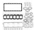
发动机大修包
|
型号
|
数量
|
描述
|
|
TZ10211
|
6
|
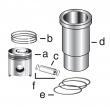
活塞缸套组件
|
|
TRE529319
|
6
|
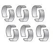
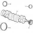
主轴瓦(标准)
|
|
TRE529320
|
1
|
止推瓦(标准)
|
|
TRE529318
|
6
|
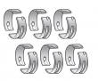
连杆瓦(标准
|
|
TRE543639
|
1
|
后油封
|
|
TRE520036
|
1
|
SEAL, 曲轴 REAR
|
|
TRE528400
|
1
|
大修包
|
|
TR74008
|
6
|
连杆衬套
|
|
TR501035
|
12
|
连杆螺钉
|
|
TR527877
|
6
|
凸轮轴衬套
|
发动机内部修理套件
|
型号
|
数量
|
描述
|
|
TZ10211
|
6
|
活塞缸套组件
|
|
TRE529319
|
6
|
主轴瓦(标准)
|
|
TRE529320
|
1
|
止推瓦(标准)
|
|
TRE529318
|
6
|
连杆瓦(标准
|
|
TRE528402
|
1
|
GASKET, CYL HEAD SET
|
|
TR532464
|
1
|
GASKET, OIL PAN
|
|
TR501035
|
12
|
连杆螺钉
|
约翰迪尔 6090A 9.0L
|
|
|
发动机和设备型号
|
孔径:
4.664 in 118.35 mm
冲程:
5.400 in 136 mm
|
|
|
block&you discover that the head is not positioned correctly on locating dowels, remove cylinder head and install a new gasket. do not try to reposition cylinder head on the same gasket again since the fire ring will possibly be damaged. 2. lower cylinder head in correct position on block using lifting straps&a hoist. make sure that head is positioned correctly over dowels&that it is all the way down on gasket. continued on next page ctm100 (20mar01) 02-020-57 powertech 10.5 l & 12.5 l diesel engines 032001 pn=129 cylinder head&valves 02 020 58 rg,rg34710,95 –19–27nov00–2/2 rg8347 –un–19may98 cylinder head cap screw torque sequence important: whenever cylinder head is removed for service, all cap screws must be replaced when head is installed. these cap screws can only be used one time. note: all 26 cylinder head cap screws are the same length. 3. dip new cap screws&washers in clean sae 30 engine oil. allow excess to drain off threads. 4. initially tighten no. 17 cap screw to specifications. specification step 1—cylinder head no. 17 cap screw—initial torque 100 n?m (74 lb-ft) this prevents head from tipping during tightening sequence. 5. use torque-turn method to tighten all cylinder head cap screws to specifications. (see torque-turn cylinder head cap screws next in this group.) ctm100 (20mar01) 02-020-58 powertech 10.5 l & 12.5 l diesel engines 032001 pn=130 cylinder head&valves 02 020 59 rg,rg34710,96 –19–28nov00–1/2 torque-turn cylinder head cap screws rg8346 –un–09dec97 torque-turn cylinder head cap screws a—front of engine arrow (a) points toward front of engine. important: do not use multi-viscosity oils to lubricate cap screws. 1. lubricate cap screws with clean sae 30 engine oil and install in their proper locations as outlined previously. 2. if not done, initially tighten cap screw no. 17 to specification to prevent head from tipping during tightening sequence. specification step 1—cylinder head no. 17 cap screw—initial torque 100 n?m (74 lb-ft) following figure on previous page, sequentially start at cap screw no. 1&proceed through cap screw no. 26 and tighten all cap screws to 163 n?m (120 lb-ft). specification step 2—all cap screws (nos. 1—26)—initial torque . 163 n?m (120 lb-ft) 3. wait 5 minutes&verify above torque. specification step 3—verify all cap screws (nos. 1—26)—torque . 163 n?m (120 lb-ft) 4. using an oil-proof pen, pencil,/marker, draw a line parallel to the crankshaft across the entire top of each cap screw head. this line will be used as a reference mark. important: if a cap screw is accidentally tightened more than 90° in first sequence, do not loosen cap screw but make adjustments in the next tightening sequence. 5. sequentially (start at cap screw no. 1&proceed through cap screw no. 26) turn each cap screw 90°. line on top of cap screw will be perpendicular to crankshaft. ctm100 (20mar01) 02-020-59 powertech 10.5 l & 12.5 l diesel engines 032001 pn=131 continued on next page cylinder head&valves 02 020 60 rg,rg34710,96 –19–28nov00–2/2 specification step 4—all cap screws (nos. 1—26)—initial torque-turn . 90° important: cap screws must not be tightened more than a total of 180°—190°. 6. finally, sequentially (start at cap screw no. 1 and proceed through cap screw no. 26) turn each cap screw an additional 90°, so that line on top of cap screw is as close as possible to being parallel to the crankshaft. it is not necessary to obtain the final turn in one swing of the wrench. total amount of turn from steps 5, and 6, is 180°—190°. specification step5—all cap screws (nos. 1— 26)—final torque-turn . 90° cylinder head torque procedure summarized as follows: cylinder head—specification step 1—no. 17 cap screw— initial torque 100 n?m (74 lb-ft) step 2—all cap screws (nos. 1—26)—initial torque . 163 n?m (120 lb-ft) step 3—wait 5 minutes and verify all cap screws (nos. 1— 26)—torque . 163 n?m (120 lb-ft) step 4—all cap screws (nos. 1—26)—initial torque-turn . 90° step 5—all cap screws (nos. 1—26)1—final torque-turn 90° 1 total torque-turn for steps 4&5 is 180°. ctm100 (20mar01) 02-020-60 powertech 10.5 l & 12.5 l diesel engines 032001 pn=132 cylinder head&valves 02 020 61 rg,rg34710,97 –19–01nov00–1/9 install rocker arm assembly rg8227a –un–05dec97 timing pin in crankshaft a—timing pin 1. make sure crankshaft&camshaft are locked at no. 1 cylinder tdc with timing pins (a) installed. rg,rg34710,97 –19–01nov00–2/9 rg8304 –un–06dec97 lifting rocker arm assembly a—jdg970a rocker arm lifting fixture b—cap screw c—cap screw important: later 12.5 l engines (30000— ) use different rocker arm assembly parts. refer to parts catalog for correct applications. 2. with rocker arms properly spaced on shaft&cap screws (b)&(c) on each end, install jdg970a rocker arm assembly lifting fixture (a) onto rocker arm&shaft assembly. 3. firmly depress buttons on two lifting arms, install lifting plate with two locator pins&lifting arms positioned in holes of rocker arm shaft. release buttons so that ball actuating pins lock onto shaft&can be safely lifted. important: always loosen all intake, exhaust and eui rocker arm adjusting screws before removal/installation of rocker arm assembly to relieve pressure. this allows for a more uniform rocker arm cap screw clamp load&reduces the possibility of damage to valve train components. 4. install front&rear rocker arm&shaft assembly onto locating roll pins of cylinder head. make sure all push rods are aligned properly. ctm100 (20mar01) 02-020-61 powertech 10.5 l & 12.5 l diesel engines 032001 pn=133 continued on next page cylinder head&valves 02 020 62 rg,rg34710,97 –19–01nov00–3/9 rg8262a –un–06dec97 rocker arm oil tube rg10343 –un–09sep99 valve bridges&push tubes a—hold-down clamps b—oil tube (early engines with dual rail fuel system) c—push tubes d—valve bridges e—slots important: do not reuse rocker arm shaft hold-down clamp cap screws. ensure that new cap screws are used for reassembly. note: on early engines with dual rail fuel system, install hold-down clamps (a) with oil tube (b) at second clamp location from front&rear of engine. 5. install rocker arm hold-down clamps. install cap screws finger tight. 6. install twelve valve bridges (d) with slots (e) facing exhaust manifold side of engine. be sure each bridge is properly seated onto two respective intake and exhaust valves within a given cylinder. 7. install twelve push tubes (c) on top of bridges. 8. make sure intake, exhaust,&injector rocker arm adjusting screws are loose to eliminate binding shaft as clamps are tightened. 9. initially tighten rocker arm hold-down cap screws in the end of each shaft to pull shaft down onto locking roll pins. next, going from front-to-rear of engine, tighten hold-down clamp cap screws to the following specification: specification rocker arm shaft hold-down clamp cap screws (all engines)—initial torque 30 n?m (22 lb-ft) make an additional pass from front-to-rear&verify torque specification above. important: torque-turn procedures for rocker arm shaft clamp cap screws differ between engines with dual rail&single rail fuel systems. use proper procedure for engine application. 10. torque-turn rocker arm shaft clamp cap screws using proper procedure for type of fuel system as detailed on following pages. ctm100 (20mar01) 02-020-62 powertech 10.5 l & 12.5 l diesel engines 032001 pn=134 continued on next page cylinder head&valves 02 020 63 rg,rg34710,97 –19–01nov00–4/9 rg9200a –un–30jul99 torque-turn clamp cap screws rg9202a –un–30jul99 torque-turn clamp cap screws a—line on socket b—line on shaft clamp c—line on spacer torque-turn rocker arm hold-down clamp cap screws on engines with dual rail fuel systems 1. after applying initial torque of 30 n?m (22 lb-ft), start at front cap screw&proceed to the rear and torque-turn each cap screw 60° ± 5° as follows: ? position a six point socket onto rocker arm shaft clamp cap screw. ? with clockwise tension on socket (viewed from rear of engine), mark a line (a) on socket&another aligning mark on shaft clamp (b) [or spacers (c) at each end location)]. continued on next page ctm100 (20mar01) 02-020-63 powertech 10.5 l & 12.5 l diesel engines 032001 pn=135 cylinder head&valves 02 020 64 rg,rg34710,97 –19–01nov00–5/9 rg9201a –un–30jul99 torque-turn clamp cap screws rg9203a –un–30jul99 torque-turn clamp cap screws a—line on socket b—line on shaft clamp c—line on spacer ? remove socket from cap screw&rotate socket counterclockwise (viewed from rear of engine) one flat&reinstall on cap screw. marks should now be 60° apart. ? tighten cap screws (clockwise) until marks on socket (a)&shaft clamp [or spacers (c) at each end location] are aligned. note: if cap screw is tightened beyond aligning mark, loosen cap screw&repeat procedure starting with initial torque of 30 n?m (22 lb-ft). 2. repeat procedure on remaining cap screws and torque-turn cap screws to the following specifications. specification rocker arm shaft hold-down clamp cap screws (dual rail fuel system)—final torque-turn . 60° ± 5° important: position electronic unit injector wiring harness so that wires do not touch rocker arms. 3. install unit injector wiring harness. apply loctite? 222 (ty24311) thread lock&sealer (low strength) to harness cap screws. tighten cap screws to specifications below. specification unit injector wiring harness bracket-to-rear of head—torque 25 n?m (18 lb-ft) unit injector wiring harness solenoid wire retaining nut1— torque . 2.0 n?m (1.5 lb-ft) unit injector harness clips-to-rocker arm shaft clamps—torque 35 n?m (26 lb-ft) 4. adjust valve-to-bridge clearance&injector preload. (see check&adjust valve assembly clearances&injector preload, earlier in this group.) loctite is a registered trademark of loctite corp. 1apply loctite 222 (ty24311) thread lock&sealer (low strength). ctm100 (20mar01) 02-020-64 powertech 10.5 l & 12.5 l diesel engines 032001 pn=136 continued on next page cylinder head&valves 02 020 65 rg,rg34710,97 –19–01nov00–6/9 rg9743 –un–04dec98 inspect bridges&push tubes a—valve bridge b—valve stems c—push tube important: thoroughly inspect intake&exhaust valve bridges (a) for proper seating on valve stems (b) from both sides of engine. also, make sure that push tubes (c) are properly seated in top of valve bridges. use a flashlight&carefully check each bridge (for proper seating on valve stems) from both sides of the engine. lift up on each bridge to verify proper seating. valve bridges that are not properly seated on valve stems will result in major engine failure. before installing rocker arm cover, make sure that all eui wires are positioned so that rocker arm will not contact wires when engine is running. 5. install rocker arm cover. (see remove&install rocker arm cover, earlier in this group.) continued on next page ctm100 (20mar01) 02-020-65 powertech 10.5 l & 12.5 l diesel engines 032001 pn=137 cylinder head&valves 02 020 66 rg,rg34710,97 –19–01nov00–7/9 rg10281 –un–20aug99 index rocker cap screw rg10282 –un–20aug99 ratchet parallel to crankshaft rg10283 –un–23sep99 ratchet perpendicular to crankshaft a—line on rocker cap screw head b—ratchet parallel to crankshaft c—ratchet perpendicular to crankshaft torque-turn rocker arm hold-down clamp cap screws on engines with single rail fuel systems 1. after applying initial torque of 30 n?m (22 lb-ft), start at front cap screw&proceed to the rear and torque-turn each cap screw 90° + 10° — 0° as follows: ? using an oil proof pen, pencil,/marker, draw a line (a) parallel to the crankshaft across the entire top of each cap screw head. this line will be used as a reference mark. ? install ratchet/socket on cap screw with ratchet handle parallel (b) to crankshaft. ? tighten each cap screw 90° so ratchet handle is perpendicular (c) to crankshaft. remove ratchet/socket from cap screw&verify line on top of cap screw is perpendicular to crankshaft. note: if cap screw is tightened beyond aligning mark, loosen cap screw&repeat procedure starting with initial torque of 30 n?m (22 lb-ft). ? repeat procedure on remaining cap screws and torque-turn cap screws to the following specifications. specification rocker arm shaft hold-down clamp cap screws (single rail fuel system)—final torque-turn . 90° + 10° — 0° important: position electronic unit injector wiring harness so that wires do not touch rocker arms. 2. install unit injector wiring harness. apply loctite? 222 (ty24311) thread lock&sealer (low strength) to harness cap screws. tighten cap screws to specifications below. specification unit injector wiring harness bracket-to-rear of head—torque 25 n?m (18 lb-ft) loctite is a registered trademark of loctite corp. ctm100 (20mar01) 02-020-66 powertech 10.5 l & 12.5 l diesel engines 032001 pn=138 continued on next page cylinder head&valves 02 020 67 rg,rg34710,97 –19–01nov00–8/9 specification unit injector wiring harness solenoid wire retaining nut1— torque . 2.0 n?m (1.5 lb-ft) unit injector harness clips-to-rocker arm shaft clamps—torque 35 n?m (26 lb-ft) 3. adjust valve-to-bridge clearance&injector preload. (see check&adjust valve assembly clearances&injector preload, earlier in this group.) 1apply loctite 222 (ty24311) thread lock&sealer (low strength). rg,rg34710,97 –19–01nov00–9/9 rg9743 –un–04dec98 inspect bridges&push tubes a—valve bridge b—valve stems c—push tube important: thoroughly inspect intake&exhaust valve bridges (a) for proper seating on valve stems (b) from both sides of engine. also, make sure that push tubes (c) are properly seated in top of valve bridges. use a flashlight&carefully check each bridge (for proper seating on valve stems) from both sides of the engine. lift up on each bridge to verify proper seating. valve bridges that are not properly seated on valve stems will result in major engine failure. before installing rocker arm cover, make sure that all eui wires are positioned so that rocker arm will not contact wires when engine is running. 4. install rocker arm cover. (see remove&install rocker arm cover, earlier in this group.) ctm100 (20mar01) 02-020-67 powertech 10.5 l & 12.5 l diesel engines 032001 pn=139 cylinder head&valves 02 020 68 rg,rg34710,98 –19–16oct00–1/1 complete final assembly for cylinder head installation 1. install camshaft gear access cover. (see install timing gear cover in group 040.) 2. install thermostat housing/water manifold assembly. (see remove&install thermostat housing in group 070.) 3. install intake manifold. (see remove, inspect and install intake manifold in group 080.) install exhaust manifold. (see remove, inspect and install exhaust manifold in group 080.) install turbocharger. (see install turbocharger in group 080.) 4. install fuel supply pump. refer to the appropriate fuel system repair manual. lucas ecu controlled fuel systems: ? see remove&install fuel supply pump in ctm115, section 02, group 090. john deere level 6 ecu controlled fuel systems: ? see remove&install fuel supply pump in ctm188, section 02, group 090 (dual rail fuel systems). ? see remove&install fuel supply pump in ctm188, section 02, group 091 (single rail fuel systems). 5. install fuel manifold assembly (if equipped) from rear of cylinder head. see the appropriate fuel system repair manual. lucas ecu controlled fuel systems: ? see remove&install fuel manifold in ctm115, section 02, group 090 (dual rail fuel system). john deere level 6 ecu controlled fuel systems: ? see remove&install fuel manifold in ctm188, section 02, group 090 (dual rail fuel system). 6. install&securely tighten all fuel lines&fuel filter. (ctm115, section 02, group 090/ctm188, section 02, group 090/091.) 7. fill engine with proper fuel&coolant. (section 01, group 002.) 8. perform engine break-in. (see perform engine break-in in group 010.) ctm100 (20mar01) 02-020-68 powertech 10.5 l & 12.5 l diesel engines 032001 pn=140 group 030 cylinder block, liners, pistons,&rods 02 030 1 rg,rg34710,105 –19–30sep97–1/1 front plate-to-cylinder block torque sequence rg8814 –un–20may98 front plate torque sequence ctm100 (20mar01) 02-030-1 powertech 10.5 l & 12.5 l diesel engines 032001 pn=141 cylinder block, liners, pistons,&rods 02 030 2 rg,rg34710,106 –19–01nov00–1/4 remove&install cylinder block front plate rg8787 –un–10dec97 front plate&timing gear cover exploded view a—timing gear cover d—oil pump gear g—front plate gasket i—without auxiliary drive b—camshaft gear e—screws (5 used) h—auxiliary drive gear gear c—idler gear f—front plate remove front plate 1. lock engine at no.1 tdc compression stroke by installing jdg971 timing pins in camshaft and crankshaft. (see check&adjust camshaft-to-crankshaft timing in group 050.) 2. remove timing gear cover (a). (see remove timing gear cover in group 040.) 3. remove camshaft gear (b)&idler gear assembly (c). (see check&adjust camshaft-to-crankshaft timing in group 050.) 4. remove engine oil pump assembly (d). (see remove engine oil pump in group 060.) 5. remove auxiliary drive gear (h) if equipped. (see remove&install auxiliary drive idler gear&bearing in ctm67, oem engine acces ies, group 54.) important: tap head of countersunk cap screws sharply with a brass punch&use an allen-head adapter that does not have corners rounded off. 6. remove five countersunk screws (e)&remove front plate (f) from dowels. ctm100 (20mar01) 02-030-2 powertech 10.5 l & 12.5 l diesel engines 032001 pn=142 continued on next page cylinder block, liners, pistons,&rods 02 030 3 rg,rg34710,106 –19–01nov00–2/4 note: older front plate gaskets required the use of sealant on some of the upper threaded cap screw holes. new service gaskets are rubberized in these locations, so sealant is no longer required. 7. remove gasket (g)&discard. thoroughly clean gasket surfaces on cylinder block&front plate. if present, ensure all sealant is removed. continued on next page ctm100 (20mar01) 02-030-3 powertech 10.5 l & 12.5 l diesel engines 032001 pn=143 cylinder block, liners, pistons,&rods 02 030 4 rg,rg34710,106 –19–01nov00–3/4 rg8814 –un–20may98 front plate torque sequence install front plate important: all gasket contact surfaces must be clean, dry,&free of sealant&oil. earlier service front plate gaskets used sealant. new gaskets do not require sealant. 1. install new gasket onto dowels in cylinder block. 2. install front plate onto front face of block. 3. install five countersunk screws&tighten to specifications, following sequence in illustration. specification front plate-to-cylinder block cap screws—torque 50 n?m (37 lb-ft) 4. install engine oil pump assembly. (see install engine oil pump in group 060.) 5. install idler gear&camshaft gear. adjust gear backlash. (see check&adjust camshaft-to-crankshaft timing in group 050.) 6. install auxiliary drive gear (if equipped). (see remove and install auxiliary drive idler gear and bearing in ctm67, oem engine acces ies, group 54.) 7. install timing gear cover. (see install timing gear cover in group 040.) 8. install engine oil pan. (see install engine oil pan in group 060.) 9. install crankshaft vibration damper&pulley. (see install crankshaft vibration damper and front oil seal in group 040.) 10. remove jdg971 timing pins&install rocker arm cover. (see remove&install rocker arm cover in group 020.) 11. install crankshaft timing pin plug&tighten to specifications. ctm100 (20mar01) 02-030-4 powertech 10.5 l & 12.5 l diesel engines 032001 pn=144 continued on next page cylinder block, liners, pistons,&rods 02 030 rg,rg34710,106 –19–01nov00–4/4 specification crankshaft timing pin plug— torque . 33 n?m (24 lb-ft) 5 ctm100 (20mar01) 02-030-5 powertech 10.5 l & 12.5 l diesel engines 032001 pn=145 cylinder block, liners, pistons,&rods 02 030 6 rg,rg34710,1112 –19–06may99–1/1 preliminary liner, piston,&rod checks scuffed/scored pistons: ? overheating. ? overfueling. ? insufficient lubrication. ? insufficient cooling. ? improper piston-to-liner clearance. ? coolant leakage into crankcase. ? misaligned/bent connecting rod. ? improperly installed piston. ? low oil level. ? improper operation. ? incorrect connecting rod bearing clearance. ? carbon build-up in ring groove. ? improper engine break-in. ? worn piston. ? contaminated oil. ? distorted cylinder liner. ? plugged piston cooling orifice. ? ingestion of dust through air intake. worn/broken compression rings: ? insufficient lubrication. ? insufficient cooling. ? improper ring installation. ? improper timing. ? abrasives in combustion chamber. clogged oil control ring: ? improper oil. ? excessive blow-by. ? contaminated oil. ? improper periodic service. ? low operating temperature. stuck rings: ? improper oil classification. ? improper periodic service. ? poor operating conditions. ? coolant leakage into crankcase. ? excessive cylinder liner taper. mottled, grayish/pitted compression rings: ? internal coolant leaks. dull satin finish&fine vertical scratches on rings: ? dirt&abrasives in air intake system. piston pin&snap ring failure: ? misaligned connecting rod. ? excessive crankshaft end play. ? incorrect snap rings. broken connecting rod: ? inadequate piston-to-liner clearance. ? worn connecting rod bearing. ? distorted cylinder liner. ? piston pin failure. cylinder liner wear&distortion: ? incorrectly installed compression rings. ? insufficient lubrication. ? uneven cooling around liner. ? inadequate piston-to-liner clearance. ? liner bore damage. warped cylinder block: ? insufficient cooling. ctm100 (20mar01) 02-030-6 powertech 10.5 l & 12.5 l diesel engines 032001 pn=146 cylinder block, liners, pistons,&rods 02 030 7 dpsg,ouo1004,871 –19–30jul99–1/1 connecting rods—general information rg10300 –un–27aug99 connecting rods rg9616 –un–02dec98 precision joint? rod (later engines) a—tongue-and-groove rod (early engines) b—precision joint? rod (later engines) c—precision joint? details earlier engines have the traditional tongue-and-groove between the connecting rod&cap (a). later engines have the precision joint? rod&cap (b). to create the precision joint?, the connecting rod is notched with a laser beam. then a precision mandrel in the rod bore is powered to separate the cap from the rod at the joints (c). both types of rods provide a strong joint. removal and installation is similar, with differences noted, including different torque specifications for cap screws. important: replace rods with the same type. do not mix tongue-and-groove with precision joint? rods in the same engine. see parts catalog for recommendations. precision joint is a trademark of deere & company ctm100 (20mar01) 02-030-7 powertech 10.5 l & 12.5 l diesel engines 032001 pn=147 cylinder block, liners, pistons,&rods 02 030 8 rg,rg34710,107 –19–01nov00–1/4 remove pistons&connecting rods rg8203 –un–05dec97 piston&rod exploded view rg8299b –un–06dec97 removing piston spray jets a—piston with rings b—piston pin c—snap ring (2 used) d—connecting rod with bushing e—rod bearings f—connecting rod cap g—special cap screws h—piston spray jet the engine does not always have to be removed from the machine to service the pistons&connecting rods. if engine is to be removed, see your machine technical manual. note: the piston&liner sets on later 12.5 l engines are different from earlier engines. do not mix sets in engines. see parts catalog for correct applications. caution: do not drain engine coolant until it cools below operating temperature. then slowly loosen block drain valve to relieve any pressure. 1. drain all coolant&engine oil. 2. remove all piston spray jets. note: if engine is to be completely disassembled, follow engine disassembly sequence in group 010. 3. remove cylinder head. (see remove cylinder head in group 020.) 4. remove oil pan. (see remove engine oil pan in group 060.) remove oil pick-up tube. (see remove and install oil pickup tube in group 060.) continued on next page ctm100 (20mar01) 02-030-8 powertech 10.5 l & 12.5 l diesel engines 032001 pn=148 cylinder block, liners, pistons,&rods 02 030 9 rg,rg34710,107 –19–01nov00–2/4 rg8302 –un–06dec97 bolting liners down a—long cap screws b—thick washers c—bolt down cylinder liners important: do not rotate crankshaft with cylinder head removed unless liners are bolted down. bolt liners down before removing piston. cap screws&washers must be tightened to 68 n?m (50 lb-ft) to achieve an accurate reading when checking liner standout (height above block), as detailed later in this group. 5. use seven m16 x 2.0 x 55 mm (2.17 in.) long cap screws (a)&5/8 in. id x 1-3/4 in. od x 3.18 mm (1/8 in.) thick washers (b) to bolt down cylinder liners (c) in the seven locations as shown. tighten cap screws to specifications. specification cylinder liner cap screws (for checking liner standout)— torque . 68 n?m (50 lb-ft) 6. before removing pistons, visually inspect condition of cylinder liners with pistons at bottom dead center “bdc”. liners will require replacement if: ? the crosshatch honing pattern is not visible immediately below the top ring turn-around area. ? liners are pitted/contain deep vertical scratches that can be detected by the fingernail. no further inspection is required if any one of the above conditions is found. continued on next page ctm100 (20mar01) 02-030-9 powertech 10.5 l & 12.5 l diesel engines 032001 pn=149 cylinder block, liners, pistons,&rods 02 030 10 rg,rg34710,107 –19–01nov00–3/4 rg8364 –un–09dec97 using liner ridge reamer a—jt07277 ridge reamer note: always follow manufacturer’s directions provided with ridge reamer. 7. remove carbon ridge from liner bore with a scraper or jt07277 ridge reamer (a). use compressed air to remove loose carbon from cylinders. continued on next page ctm100 (20mar01) 02-030-10 powertech 10.5 l & 12.5 l diesel engines 032001 pn=150 cylinder block, liners, pistons,&rods 02 030 11 rg,rg34710,107 –19–01nov00–4/4 rg8396a –un–09dec97 removing rod caps rg8398 –un–21may98 measuring rod bushing oil clearance a—rod caps 8. mark rods, pistons,&caps to ensure correct assembly in same location. important: keep bearing inserts with their respective caps for rod&main bearings. 9. remove all rod caps (a) with bearings. note: use plastigage? to determine bearing-to-journal oil clearance as directed by the manufacturer. plastigage? will determine bearing-to-journal oil clearance, but will not indicate the condition of either surface. 10. measure rod bearing-to-journal oil clearance with plastigage? before removing piston&rod assembly. record measurements. (see inspect and measure connecting rod bearings, later in this group.) important: hold on to piston to prevent piston from dropping. piston will drop once piston rings have cleared cylinder liner bore. if liners are to be reused, be extremely careful not to let connecting rod hit liner bore when removing piston and rod assembly. 11. gently tap piston through top of cylinder block from the bottom. 12. remove remaining pistons&rods from engine. plastigage is a registered trademark of dana corp. ctm100 (20mar01) 02-030-11 powertech 10.5 l & 12.5 l diesel engines 032001 pn=151 cylinder block, liners, pistons,&rods 02 030 12 rg,rg34710,108 –19–13aug99–1/2 measure cylinder liner standout (height above block) rg6439 –un–03nov97 liner standout rg8330b –un–09dec97 measuring liner standout a—liner height b—jdg451 gauge c—kjd10123 gauge important: remove all gasket material, rust, carbon and other foreign material from top deck of cylinder block. use compressed air to remove all loose foreign material from cylinders&top deck. note: liners having obvious defects must be replaced as a matched piston&liner set. 1. bolt liners down in seven locations using cap screws and washers. (see remove pistons and connecting rods, earlier in this group.) tighten cap screws to 68 n?m (50 lb-ft). specification cylinder liner cap screws (for checking liner standout)— torque . 68 n?m (50 lb-ft) 2. using jdg451 gauge (b) along with d17526ci (english scale)/d17527ci (metric scale) dial indicator/kjd10123 gauge (c), measure liner height (a) for all cylinders. 3. measure each liner in four places at approximately 1, 5, 7,&11 o’clock positions as viewed from rear of engine (flywheel end). 泰州强鹿柴油机止推轴承RE65168供应商,秦皇岛强鹿机滤RE504836供货商,泰安强鹿柴油滤清器P556745多少钱,运城柴油发电机配件约翰迪尔哪家买,淮安平衡轴铜套约翰迪尔4045柴油机批发,芜湖强鹿皮带涨紧轮一级代理,马鞍山约翰迪尔止推轴承瓦RE65168批发商,长沙约翰迪尔机油底壳垫片R521498价格,宁波强鹿平衡轴铜套TR115299价格,庆阳约翰迪尔6068柴油机活塞环公司,六安JohnDeere电热塞厂家价格,盘锦约翰迪尔RE522688滤芯价格行情,宜昌强鹿活塞销R502755信息,长沙强鹿滤芯滤清器RT6005011112批发商,眉山约翰迪尔强鹿机油底壳垫片R520844厂家价格,遂宁强鹿水泵总成RE500734信息,临沂约翰迪尔RE521348曲轴哪里买,钦州强鹿柴油机水泵AR97708的价格,record all measurements by cylinder number. note: variations in measurement readings may occur within one cylinder and/or between adjacent cylinders. 4. if liner standout is below specification, measure liner flange thickness. (see measure liner flange thickness later in this group.) measure liner counterbore depth in cylnder block. (see inspect and clean cylinder block, later in this group.) continued on next page ctm100 (20mar01) 02-030-12 powertech 10.5 l & 12.5 l diesel engines 032001 pn=152 cylinder block, liners, pistons,&rods 02 030 13 rg,rg34710,108 –19–13aug99–2/2 specification cylinder liner height (standout)—height above block 0.030—0.117 mm (0.0012—0.0046 in.) . maximum permissible height difference at nearest point of two adjacent liners/within one liner 0.05 mm (0.002 in.) cylinder liner shims available— thickness 0.05 mm (0.002 in.) thickness 0.10 mm (0.004 in.) important: one liner shim only may be installed under any given liner flange. 5. add shims/replace any liner that does not meet standout specification at any location. rg,rg34710,109 –19–13aug99–1/2 remove cylinder liners using d01062aa or d01073aa cylinder liner puller rg1179 –un–05dec97 removing cylinder liners a—liner b—cylinder liner puller c—jaw 1. remove cap screws&washers securing liners to cylinder block. 2. number cylinder liners&mark fronts to ensure correct assembly. note: each cylinder liner must be reinstalled in same cylinder bore from which removed. always keep matched pistons&liners together. 3. use d01062aa/d01073aa cylinder liner puller (b) with a 2.27 kg (5.0 lb) slide hammer to remove cylinder liner (a). important: when using d01062aa (or d01073aa) cylinder liner puller (b) to remove liner (a), be sure jaw (c) of puller is correctly positioned before attempting to remove liner. do not over-tighten liner puller to remove liners. doing so could easily break liners. ctm100 (20mar01) 02-030-13 powertech 10.5 l & 12.5 l diesel engines 032001 pn=153 continued on next page cylinder block, liners, pistons,&rods 02 030 14 rg,rg34710,109 –19–13aug99–2/2 rg6668 –un–05dec97 cylinder liner packing a—square packing (neoprene) b—red o-ring (silicone) c—black o-ring (viton) d—cylinder block e—cylinder liner f—coolant passage 4. remove the cylinder liner square packing (a) from liner (e). 5. remove red o-ring (b)&black o-ring (c) from cylinder block (d). ctm100 (20mar01) 02-030-14 powertech 10.5 l & 12.5 l diesel engines 032001 pn=154 cylinder block, liners, pistons,&rods 02 030 15 dpsg,ouo1004,1026 –19–09sep99–1/2 remove cylinder liners using jdg1145 cylinder liner service set rg10341 –un–10sep99 jdg1145 installation rg10339 –un–09sep99 remove cylinder liner a—jdg1145 b—slide hammer c—liner puller note: jdg1145 liner puller (a) shown with liner removed to illustrate proper assembly of tool. 1. remove cap screws&washers securing liners to cylinder block. 2. number cylinder liners&mark fronts to ensure correct assembly. note: each cylinder liner must be reinstalled in same cylinder bore from which removed. always keep matched pistons&liners
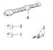
KEY PART NO. PART NAME QTY SERIAL NO. F F F REMARKS
1 R60914 SET SCREW 1 X X
2 R53918 PACKING 1 X X
3 T31556 NUT 1 X X
4 R68715 PIN 1 X X
5 AR89339 SEAL 1 X X
6 AR89578 LEVER 1 X X
7 24M7054 WASHER 1 X X 6.400 X 12 X 1.600 MM
8 T24229 LOCK WASHER 2 X X
9 R68716 NUT 1 X X
10 R129240 LEVER 1 -XXXXXX X (A)
R112128 LEVER 1 X (A)
11 19M8826 SCREW 2 X X M6 X 16
12 R53976 SCREW 1 X X (B)
13 24H1287 WASHER 1 X X (B) 9/32" X 5/8" X 0.065"
14 RE54741 LEVER 1 X (C) (LH)
R98677 LEVER 1 X (C)
15 R68438 RETAINER 1 X X
16 R53955 O-RING 1 X X
(A) THROTTLE (TWO HOLES AT TOP) (B) NOT INCLUDED (C) SHUT-OFF
MANETTE DES GAZ NON INCLUS ROBINET D’ARRET
DROSSELKLAPPE NICHT MIT ABSCHALTUNG
ACCELERATORE NON COMPRESO RUBINETTO D’ARRESTO
ACELERADOR NO FORMA PARTE GRIFO DECIERRE
GASREGLAGE INGAAR INTE AVSTAENGING
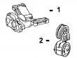
KEY PART NO. PART NAME QTY SERIAL NO. F F F REMARKS
1 R126207 BRACKET 1 X
2 14M7165 LOCK NUT 2 X M6
3 RE504223 SOLENOID 1 X (A) (24 V) (SUB FOR RE54747)
4 19H1914 CAP SCREW 1 X 1/4" X 1"
5 24H1287 WASHER 1 X 9/32" X 5/8" X 0.065"
6 RE54741 LEVER 1 X
7 03M7068 BOLT 1 X M6 X 20
8 19H1900 CAP SCREW 2 X 5/16" X 3/4"
9 24H1136 WASHER 2 X 11/32" X 11/16" X 0.065"
10 R104592 PIPE PLUG 1 X
11 R128694 BASE 1 X (SUB FOR R127415) (ALSO ORDER (2)
R104592)
(A) ENERGIZE TO RUN
METTRE SOUS TENSION POUR FAIRE MARCHER
FUER BETRIEB AKTIVIEREN
ATTIVARE PER IL FUNZIONAMENTO
ACTIVAR PARA MARCHA
MAGNETISERA FOER ATT SAETTA IGAANG
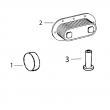
KEY PART NO. PART NAME QTY SERIAL NO. F F F REMARKS
1 .. HOLDER NA X X
2 T24210 O-RING 6 X X
3 R76358 O-RING 1 X X
4 14M7272 NUT 3 X X M6
5 12M7006 LOCK WASHER 3 X X 0.236"
6 R67879 GASKET 1 X X
7 51M4238 SEALING RING 1 X X (SUB FOR R53899)
8 AR77114 CONTROL VALVE 1 X X
9 R53901 WASHER 1 X X
10 R63016 ADAPTER 1 X X
11 R67364 ELBOW FITTING 1 -087549 X X
RE502650 FITTING 1 087550- X X
KEY PART NO. PART NAME QTY SERIAL NO. F F F REMARKS
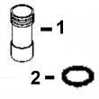
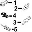
1 RE65265 HAND PRIMER 1 X X (SUB FOR RE48048)
2 R54025 WASHER 1 X X
3 R26448 O-RING 2 X X
4 RE10258 ELBOW FITTING 2 X (M14 X 5/8 IN.)
RE34128 ELBOW FITTING 1 X (IN)
RE10258 ELBOW FITTING 1 X (OUT)
5 R67879 GASKET 1 X X
6 RE46375 FUEL PUMP 1 X X (ROBERT BOSCH)
7 51M4238 SEALING RING 1 X X
8 R83490 FITTING 1 X X