帕金斯发动机涡轮增压器的维修保养技术参数资料3012
帕金斯发动机涡轮增压器的维修保养技术参数资料3012
To remove
1 Remove the air ducts between the air cleaner, the
turbocharger and the radiator.
2 Disconnect the pipe that supplies oil to the
turbocharger. Disconnect also the drain pipes.
3 Disconnect and remove the exhaust pipe from the
elbow and remove the elbow, and the exhaust
bellows if relevant.
4 If relevant for early engines, bend back the tabs of
the lock washers on the bolts that retain the
turbocharger. Remove the bolts and lift away the
turbocharger from the engine. For new engines,
release the four nuts which hold the turbocharger to
the exhaust manifold; remove the plain washers and
lift away the turbocharger.
1 Ensure that there is no internal contamination of the
castings of the induction manifold and the exhaust
manifold. Check that they are not damaged and that
there is no erosion on the joint faces. Check that the
pipes for the supply of lubricating oil and the drain
pipes are clean, and that they are not damaged.
2 Ensure that the joint faces of the turbocharger and
the exhaust manifold are absolutely clean. Ensure
that the stainles s steel studs in the joint face of the
exhaust manifold are not damaged and apply
’Copaslip’ anti-seize compound to the threads. Put
the turbocharger on the joint face of its exhaust
|
|
manifold and retain with the four stainless steel nuts
and the plain washers. Tighten securely the nuts.
3 Refit the exhaust bellows if relevant, the elbow and
the exhaust system.
4 Use new hoses to fit the air ducts between the
turbocharger, the radiator and the air filters.
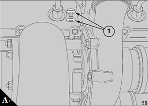
5 Before the engine is started, the bearings of the
turbocharger must be flushed with lubricating oil.
Clean around the blanking plug (A1) on the bearing
housing and remove the blanking plug from the inlet
lubricating oil into the bearing housing through the
inlet. Fit and tighten the blanking plug.
Caution: After a complete engine overhaul, a s pecial
temporary filter for the engine lubricating oil must be
fitted to the oil inlet of each turbocharger. The special
filters are not usable again, and must be removed and
discarded after the first period of running-in of the
engine.
o dismantle and to assemble
To dismantle
5 Hold upright the bearing housing and use a socket
or spanner with a tee handle to remove the nut (A14)
which retains the impeller of the compressor.
Caution: To prevent distortion, ensure that a
The relevant kit of service parts must be used when a
turbocharger is dismantled and assembled.
1 Clean the outside of the unit and use a scriber to
mark the relationships of the housings for the
bearings (A10), the compressor (A1) and the turbine
(A16).
2 Remov e the bolts (A3) and the clamps (A2) which
hold the housing of the compressor. Use a soft faced
hammer to remove the housing. Ensure that the
impeller of the compressor (A4) is not damaged
during the operation. Remove and discard the ’O’ ring
(A5).
3 Loosen the stiffnut (A17) of the ’V’ band clamp
(A18) and disengage the clamp from the flanges of
the turbine housing and the central bearing housing.
Do not press on the rotating assembly.
4 Select a socket, or a suitable spanner, of the
correct size to fit the hexagon extension on the hub of
the turbine rotor (A7) and securely fasten it in a vice.
Fit the hexagon extension in the socket or spanner.
bending moment is not applied to the shaft.
6 Use a suitable support to hold upright the bearing
housing, with the impeller of the compressor at the
top. Press the shaft of the turbine out of the housing.
The shroud (A9) of the turbine is also removed with
the shaft.
7 Remove and disc ard the piston ring ty pe seal (A8)
at the turbine rotor end of the shaft.
8 Release the bolts (A13) which retain the assembly
of the backplate (A6) and remove the assembly of the
backplate and the sealing ring (A23). Discard the
sealing ring.
9 Remove the spacer (A21) from the assembly of the
backplate. Remove and discard the two piston type
rings (A22) from the spacer.
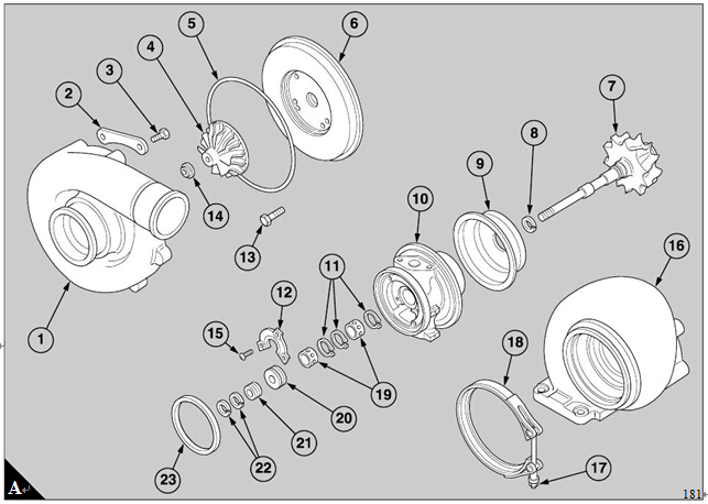
10 Remove three sc rews (A15) that fasten the thrust
plate (A12) to the bearing housing. Remove the
thrust plate and the collar (A20).
11 Remove the circ lips (A11) and the bearings (A19)
from the bearing housing and discard the bearings.
To assemble
Caution: Before the turbocharger is assembled,
lubricate lightly all bearing surfaces with clean engine
lubricating oil. The circlips which retain the bearings
have round shoulders on one side. When they are
assembled, ens ure that the sides with the round
shoulders are toward the bearings.
1 Fit the inner c irclips of both bearings in the bore of
the bearing housing. Ensure that the round shoulders
are on the outer faces of the circlips.
2 Fit a new bearing in the bore of the bearing housing,
at the end for the turbine housing. Retain it by
another circlip, fitted with the round shoulder on the
inner face.
3 Fit a new bearing in the bore of the bearing housing,
at the end for the compressor. Assemble the collar
and thrust plate, and install the assembly in the
bearing housing.
Caution: All the threaded holes in the turbocharger
are metric.
4 Retain the collar and the thrust plate in the bearing
housing with three screws and tighten them to 2,5 Nm
(22 lbf in).
5 Fit a new seal and assemble the backplate to the
bearing housing. Retain with four bolts and tighten
them to 9,0 Nm (80 lbf in).
6 Fit a new piston ring type seal to the shaft of the
turbine rotor.
7 Assemble the shroud of the turbine rotor over the
shaft and insert carefully the shaft through the
bearings. Turn and move carefully the shaft in
various directions to allow the piston ring type seal to
enter its seat in the bore. Do not apply force because
the piston ring type seal can be broken easily.
8 Assemble the new piston ring type seals on to the
spacer. Fit the spac er over the shaft and carefully
compress the seals to insert it into the assembly of the
backplate.
9 Put the assembly of the bearing housing in a
suitable support to hold it upright and fit the impeller
of the compressor on to the shaft.
10 Lubricate lightly the threads of the shaft and the
contact face of the nut which retains the impeller. Fit
the nut and use a socket or a spanner with a tee
handle to tighten the nut to a torque of 3,6 to 4,7 Nm
(32 to 42 lbf in).
Caution: To prevent distortion, ensure that a
bending moment is not applied to the shaft.
11 Ensure that the faces of the impeller and the
spacer are in contact and tighten the nut another 120°
to extend the shaft 0,20 to 0,23 mm (0.008 to 0.009
in).
12 Put loosely the 'V' band clamp on the bearing
housing and apply some 'Copaslip' anti-seize
compound to the threads of the 'T' bolt. Hold the
turbine housing in the correct position and fit the 'V'
band c lamp. Tighten the stiffnut to approximately
18,1 Nm (160 lbf in), loosen to approximately 5,6 Nm
(50 lbf in) and tighten again to approximately 17,0 to
19,2 Nm (150 to 170 lbf in).
13 Fit a new 'O' ring on the outer lip of the backplate
assembly. Hold the housing of the compressor in the
correct position and fit the clamps and the bolts.
Tighten the bolts to a torque of 9,0 to 11,3 Nm (80 to
100 lbf in).
14 Check the rotating assembly for interference. If
interference occurs, find the fault and ensure that it is
corrected.
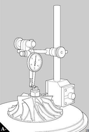
15 Check the end float and the radial movement of
the rotating assembly.
16 Set the tip of a dial test indicator in contact with the
end of the turbine rotor (A). Move manually in an axial
direction the shaft of the turbine rotor. Do not allow
the shaft to move radially. The total end-float must be
between 0,05 mm and 0,08 mm (0.002 and 0.0032
in).
17 A dial test indicator with an extended plunger is
required to measure the radial movement of the shaft.
Insert the plunger through the oil supply hole of the
bearing housing so that the end of the plunger is in
contact with the side of the shaft. The turbocharger
assembly and the dial test indicator must be
supported firmly. Hold the turbine shaft at both ends
and move it carefully towards and away from the
plunger to the limits of its movement. Ensure that an
equal amount of movement is applied to both ends of
the turbine shaft and check the reading on the dial test
indicator. The radial movement must be between
0,12 and 0,17 mm (0.0048 and 0.0065 in).
18 If the unit is to be held in storage, lubricate the
inner components and seal all openings.
帕金斯发动机涡轮增压器的清洁和检查
1 Before all the components are cleaned, inspect
them for burning, for rubbing and for other damage
that may not be seen easily after they are cleaned.
2 Soak all the components in a non-caustic cleaning
fluid and use a brush, or a scraper that is made of
plastic, to remove all the loosened depos its. Ensure
that all surfaces are clean, especially the bearing
surfaces and the bores of the bearing housing;
remove loose particles with dry compressed air. Do
not remove the s urface finish. Check especially inside
the bearing housing and ensure that it is absolutely
clean.
3 Check all the permissible worn dimensions which
are giv en in at the end of this section.
4 Renew the bearing housing if the bores for the
bearings or the piston type seals have deep
sc ratches, or are worn. Very small scratches are
acceptable.
5 Inspect the journals of the shaft for wear, scratches
or other marks. A fine abrasive can be used carefully
to remove very small s cratches. The component is
unserv iceable if there are deeper scratches and other
indications of wear.
6 Inspect the groove for the piston ring type seal for
wear and scratches. Small scratches are acceptable.
7 Inspect the turbine rotor for distortion, for erosion,
for cracks, for signs of friction and for damage caused
by impact. A small amount of erosion is acceptable if
the thickness at the tip of the blade is not less than 0,6
mm (0.025 in), and no other damage is existent. Do
NOT try to correct a bent blade.
8 Ensure that the bore of the backplate is not worn
within the area of the piston type seal. Check that the
thrust face is clean and smooth.
9 If necessary, a fine abrasive can be used carefully
to obtain smooth faces.
10 Remove the two piston ring type seals and inspect
the grooves in the spacer for wear and scratches.
Step type wear is not permissible.
11 Discard and renew the thrust plate and also the
bearings for the journals.
12 Renew the impeller of the compressor if there are
signs of friction, of erosion or of other damage.
13 Renew the shroud if it is distorted or eroded, or if
it has marks which are caused by friction.
帕金斯发动机涡轮增压器允许磨损尺寸
Fits and clearances
Turbocharger permissible worn dimensions
Bearing housing
Bore of bearing (maximum diameter) . . . . . . . . . . . . . . . . . . . . . . . . . . . . . . . . . . . . . . 20,188 mm (0.7948 in)
Bore of seal (maximum diameter) . . . . . . . . . . . . . . . . . . . . . . . . . . . . . . . . . . . . . . . . . 20,930 mm (0.8240 in)
Shaft of turbine rotor
Journal of bearing (minimum diameter). . . . . . . . . . . . . . . . . . . . . . . . . . . . . . . . . . . . . 12,992 mm (0.5115 in)
Groove for piston ring type seal (minimum diameter) . . . . . . . . . . . . . . . . . . . . . . . . . . 17,475 mm (0.6880 in)
Groove for piston ring type seal (minimum width) . . . . . . . . . . . . . . . . . . . . . . . . . . . . . . 1,740 mm (0.0685 in)
Hub (minimum diameter) . . . . . . . . . . . . . . . . . . . . . . . . . . . . . . . . . . . . . . . . . . . . . . . . 19,960 mm (0.7860 in)
Turbine rotor
Blade tips (minimum thick ness). . . . . . . . . . . . . . . . . . . . . . . . . . . . . . . . . . . . . . . . . . . . . . 0,64 mm (0.025 in)
Backplate
Bore of seal (maximum diameter) . . . . . . . . . . . . . . . . . . . . . . . . . . . . . . . . . . . . . . . . . 17,500 mm (0.6890 in)
Collar
Groove in collar (maximum width) . . . . . . . . . . . . . . . . . . . . . . . . . . . . . . . . . . . . . . . . . . 4,440 mm (0.1748 in)
Bore of collar (maximum diameter) . . . . . . . . . . . . . . . . . . . . . . . . . . . . . . . . . . . . . . . . . 7,945 mm (0.3128 in)
Spacer
Outside of spacer (minimum diameter) . . . . . . . . . . . . . . . . . . . . . . . . . . . . . . . . . . . . . 17,056 mm (0.6715 in)
Bore of spacer (max imum diameter) . . . . . . . . . . . . . . . . . . . . . . . . . . . . . . . . . . . . . . . . 7,945 mm (0.3128 in)
Groove for piston ring type seal (maximum width) . . . . . . . . . . . . . . . . . . . . . . . . . . . . . 1,765 mm (0.0695 in)
Thrust plate
Pads (minimum thicknes s) . . . . . . . . . . . . . . . . . . . . . . . . . . . . . . . . . . . . . . . . . . . . . . . 4,359 mm (0.1716 in)
Bearing
Outs ide of bearing (minimum diameter) . . . . . . . . . . . . . . . . . . . . . . . . . . . . . . . . . . . . 20,068 mm (0.7901 in)
Bore of bearing (maximum diameter) . . . . . . . . . . . . . . . . . . . . . . . . . . . . . . . . . . . . . . 13,038 mm (0.5133 in)
Impeller of compressor
Bore of impeller (maximum diameter) . . . . . . . . . . . . . . . . . . . . . . . . . . . . . . . . . . . . . . . 7,935 mm (0.3124 in)
Shroud of turbine rotor
Shroud . . . . . . . . . . . . . . . . . . . . . . . . . . . . . . . . . . . . . . . . . . . . . . . . . . . . . . . . . . . . . . . . . Renew if damaged
Turbine housing
Housing . . . . . . . . . . . . . . . . . . . . . . . . . . . . . . . . . . . . . . . . . . . . Renew if there is distortion or other damage
Housing of compressor
Housing . . . . . . . . . . . . . . . . . . . . . . . . . . . . . . . . . . . . . . . . . . . . Renew if there is distortion or other damage