帕金斯2806发动机气门间隙如何调整方法
帕金斯2806发动机气门间隙如何调整方法

How to c heck/adjust the tappet clearances
Special requirements
Operation
|
Special tools |
Tappet clearances |
||
|
Description |
Part number |
Inlet |
Exhaust |
|
Engine turning tool |
CH48 |
0,8 mm (0.05 in) |
0,76 mm (0.00 in) |
|
The tappet clearance is measured between the rocker levers and the top of the valve bridge pieces. The
operation must be done with the engine cold and stopped. Refer also to Operation -, How to check/adjust
the electronic unit injectors.
 Remove the rocker cover, Operation -.
2 Remove the cover (A2) from the flywheel housing. The top bolt (A) is the timing bolt.
Caution: If a customer-fitted speed sensor is fitted to the flywheel housing, it must be removed before the
engine turning tool can be inserted.
Remove the plug (A) from the timing bolt location in the flywheel housing and fit the timing bolt.
Note: There are two locations for the timing bolt, one at each side of the flywheel housing. Use the location
that is the most convenient.
4 Insert the engine turning tool, CH48, into the fly wheel housing through the aperture behind the cover
(A2). Us e a /2 inch drive ratchet with the turning tool to rotate the engine flywheel in the normal direction of
rotation (anti-clock wise when viewed on the flywheel) until the timing bolt engages with the threaded hole in
the flywheel. The piston of number cylinder is now at TDC (top dead centre).
Caution: If the flywheel is turned past the threaded hole, the flywheel must be turned in the opposite direction
for approximately 45 degrees and then back in the normal direction of rotation until the timing bolt engages
with the threaded hole. This is to eliminate backlash.
Continued
![]() 2800
2800
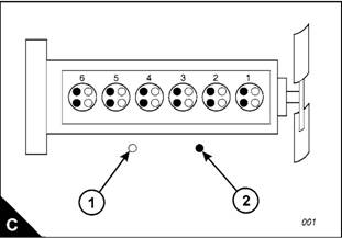
5 Check the inlet and exhaust valves of the number cylinder. If they are fully closed the piston is on its
compression stroke and the rocker levers can be moved by hand. If the rocker levers can not be moved
because the valves are slightly open, the piston is on its exhaust stroke. If it is on its exhaust stroke, withdraw
the timing bolt and turn the flywheel a further 60 degrees in the normal direction of rotation so that the number
cylinder is set to TDC on its compression stroke, then insert again the timing bolt.
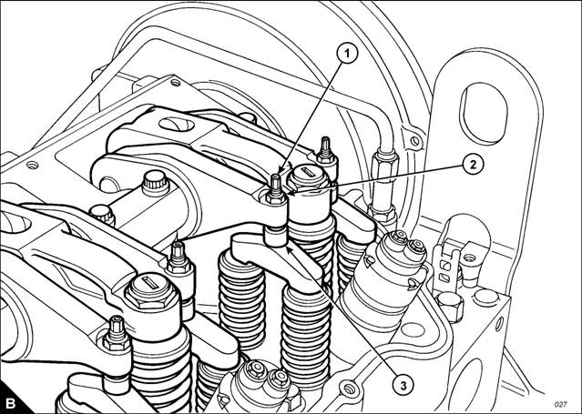
6 Before each set of tappet clearances is adjusted, ensure that the roller of the rocker lever is fully against the
camshaft lobe.
7 Use a set of feeler gauges, inserted at the position shown (B) between the valve bridge piece and the rocker
lever button, to c heck the tappet clearances for the inlet valves (C) on cylinders , 2 and 4. Adjust the
clearances if necessary. Check the tappet clearance for the exhaust valv es (C2) on cylinders , and 5, and
adjust the clearances if necessary.
Continued
Notes:
l Move each valve bridge piece before the feeler gauge is inserted to reduce the effect of the oil film.
l During the procedure, ensure that the feeler gauge is fully inserted
2800
8 After each unit has been adjusted, tighten the lock nut (B2) of the adjustment screw (B) to a torque of 0 +/
- 4 Nm (22 +/- lbf ft).
9 Withdraw the timing bolt and rotate the flywheel by 60 degrees so that the number 6 piston is at TDC on
its compression stroke. Insert again the timing bolt into the threaded hole.
0 Check the tappet clearances for the inlet valves (C) on cylinders , 5 and 6. Adjust the clearances if
necessary. Check the tappet clearances for the exhaust valves (C2) on cylinders 2, 4 and 6, and adjust the
clearances if necessary.
After each unit has been adjusted, tighten the lock nut of the adjustment screw to a torque of 0 +/- 4 Nm
(22 +/- lbf ft).
2 Check again the tappet clearances for all six cylinders.
Fit the rocker cover. Remove the engine turning tool and the timing bolt and fit the cover to the flywheel
housing. Fit the plug to the timing bolt location.