Perkins柴油机如何检查气门间隙
Perkins柴油机如何检查气门间隙

How to check the tappet clearances
Special tools
Descript ion
Engine turning tool
Tappet clearances
Part number
CH11148
Inlet
Exhaust
0,38 +/- 0,08 mm (0.015 +/- 0.003 in)
0,76 +/- 0,08 mm (0.030 +/- 0.003 in)
|
|
The tappet clearance is measured between the rocker levers and the top of the valve bridge pieces. The
operation must be done with the engine cold and stopped. Refer also to "How to check/adjust the electronic
unit injectors" on page 42.
1 Remove the rocker cover.
2 Remove the top bolt (A1) from the cover (A2) on the flywheel housing and slacken the other cover bolt to
allow the cover to open. The top bolt (A1) is the timing bolt.
Caution: If a customer-fitted speed sensor is fitted to the flywheel housing, it must be remov ed before the
engine turning tool c an be inserted.
3 Remove the plug (A3) from the timing bolt location in the flywheel housing and fit the timing bolt.
Note: There are two locations for the timing bolt, one at each side of the flywheel housing. Use the location
which is the most convenient.
4 Insert the engine turning tool, CH11148, into the flywheel housing through the aperture behind the cover
rotation (anti-clockwise when viewed on the flywheel) until the timing bolt engages with the threaded hole in
the flywheel. The piston of number 1 cylinder is now at TDC (top dead centre).
Caution: If the flywheel is turned past the threaded hole, the flywheel must be turned in the opposite direction
for approximately 45 degrees and then back in the normal direction of rotation until the timing bolt engages
with the threaded hole. This is to eliminate backlash.
User’s Handbook, TPD1516E, Issue 1
39
 4
4
2800 Series
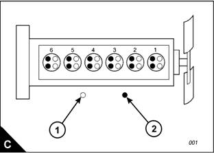
5 Check the inlet and exhaust valves of the number 1 cylinder. If they are fully closed the piston is on its
compression stroke and the rocker levers can be moved by hand. If the rocker levers can not be moved
because the valves are slightly open, the piston is on its exhaust stroke. If it is on its exhaust stroke, withdraw
the timing bolt and turn the flywheel a further 360 degrees in the normal direction of rotation so that the number
1 cylinder is set to TDC on its compression stroke, then insert again the timing bolt.
6 Before each set of tappet clearances is adjusted, ensure that the roller of the rocker lever is fully against the
camshaft lobe.
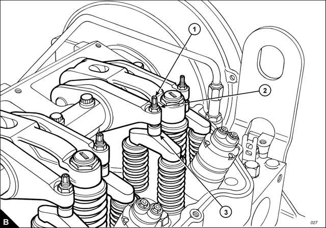
7 Use a set of feeler gauges, inserted at the position shown (B3) between the valve bridge piece and the rocker
lever button, to check the tappet clearances for the inlet valves (C1) on cylinders 1, 2 and 4. Adjust the
clearances if necessary. Check the tappet clearance for the exhaust valves (C2) on cylinders 1, 3 and 5, and
adjust the clearances if neces sary.
Notes:
Move each valve bridge piece before the feeler gauge is inserted to reduce the effect of the oil film.
During the procedure, ensure that the feeler gauge is fully inserted
8 After each unit has been adjusted, tighten the lock nut (B2) of the adjustment screw (B1) to a torque of
30 ± 4 Nm (22 ± 3 lbf ft) 3 ± 0,4 kgf m.
9 Withdraw the timing bolt and rotate the flywheel by 360 degrees so that the number 6 piston is at TDC on
its compression strok e. Insert again the timing bolt into the threaded hole.
Continued
40
User’s Handbook, TPD1516E, Issue 1
 2800 Series
10 Check the tappet clearances for the inlet valves (C1) on cylinders 3, 5 and 6. Adjust the clearances if
4
necessary. Check the tappet clearances for the exhaust valves (C2) on cylinders 2, 4 and 6, and adjust the
clearances if necessary.
11 After each unit has been adjusted, tighten the lock nut of the adjustment screw to a torque of 30 ± 4 Nm
(22 ± 3 lbf ft) 3 ± 0,4 kgf m.
12 Check again the tappet clearances for all six cylinders.
13 Fit the rock er cover. Remove the engine turning tool and the timing bolt and fit the cov er to the flywheel
housing.
14 Fit the plug to the timing bolt location.
User’s Handbook, TPD1516E, Issue 1