 English
 Espaol
 Franais
 阿拉伯
阿拉伯 中文(简)
中文(简) Deutsch
 Italiano
 Português
 日本
日本 韩国
韩国 български
 hrvatski
 esky
esky Dansk
Dansk Nederlands
 suomi
suomi Ελληνικ
 印度
印度 norsk
norsk Polski
 Roman
Roman русский
 Svenska
 Perkins珀金斯100维修手册一,Perkins珀金斯100维修手册一技术支持中心,Perkins珀金斯100维修手册一代理商,Perkins珀金斯100维修手册一销售服务中心,Perkins珀金斯100维修手册一价格规格资料查询,宁波日昕动力科技有限公司

Perkins珀金斯100维修手册一(英文)
详细描述
o remove and to fit
Operation 6-10
Special requirements
Clearance (B1) mm (in)
Standard
Service limit
0,01 - 0,15 (0.0004 - 0.0060)
0,25 (0.0098) max
Extra shims may be required to achieve the standard clearance. To check the end float refer to Operation 6-13.
1
Workshop Manual, TPD 1377E, issue 4
75
This document has been printed from SPI². Not for Resale
![]()
![]()
![]()
![]()


6
100 Series
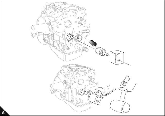
Idler hub
To fit
Operation 6-11
Special requirements
Special tools
Description
Part number
21825624
Idler hub assembly tool - 102-05, 103-07
Idler hub assembly tool - 103-10
21825625
Idler hub assembly tool - 103-13, 103-15,
104-19, 104-22
21825626
Caution: If the idler hub is removed, it must be renewed.
76
Workshop Manual, TPD 1377E, issue 4
This document has been printed from SPI². Not for Resale
![]()
![]()
![]()
![]()

6
100 Series
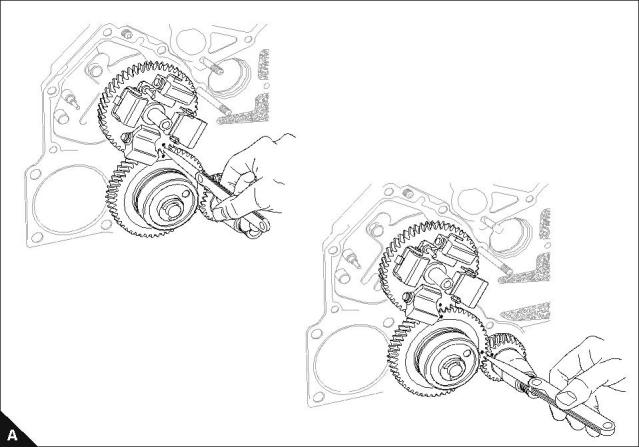
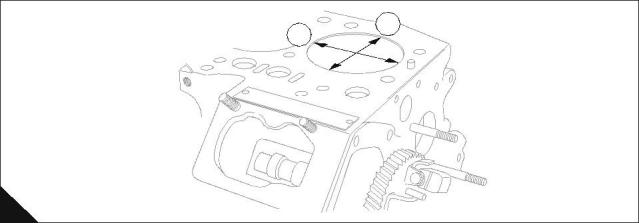
Gear teeth backlash
To check backlash
Operation 6-12
Special requirements
Timing gear tolerances mm (in)
Standard
Service limit
0,08 (0.0032)
0,25 (0.0098)
1 Align the set marks.
2 Measure the clearance with a feeler gauge.
Workshop Manual, TPD 1377E, issue 4
77
This document has been printed from SPI². Not for Resale
![]()
![]()
![]()
![]()

6
100 Series
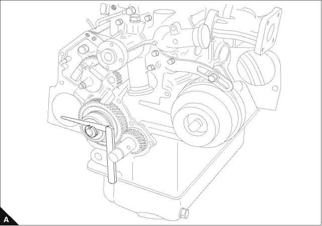
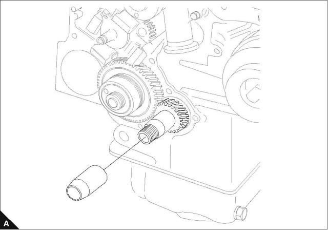
Oil pump end float
To check
Operation 6-13
Special requirements
Clearance mm (in)
Standard
Service limit
0,10 - 0,15 (0.0040 - 0.0060)
0,20 (0.0079)
Use a feeler gauge to check the end float clearance of the oil pump. Adjust with 0,1. 0,15. 0,2. and 0,5 mm
shims.
78
Workshop Manual, TPD 1377E, issue 4
This document has been printed from SPI². Not for Resale
![]()
![]()
![]()
![]()

6
100 Series
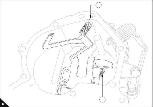
Governor spring
To locate and to check
Operation 6-14
The main governor springs are colour coded to assist with identification. The colour code is as follows:
Part Number
198217580
198217570
198217320
198217110
Description
Main Spring
Main Spring
Main Spring
Main Spring
Colour Code
Black
Purple
Yellow - green
Silver
Note: Remember the locations of the start spring (A1) and the governor spring (A2).
1
2
Workshop Manual, TPD 1377E, issue 4
79
This document has been printed from SPI². Not for Resale
![]()
![]()
![]()
![]()

6
100 Series
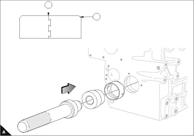
Oil seal protector
To fit
Operation 6-15
Note: Fit the oil seal protector before the timing cover is fitted.
80
Workshop Manual, TPD 1377E, issue 4
This document has been printed from SPI². Not for Resale
![]()
![]()
![]()
![]()
6
100 Series
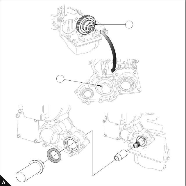
Timing cover
To fit
Operation 6-16
1 Ensure the oil pin (A1) locates in the hole (A2) in the idler gear.
2 Remove the oil seal protector after the timing cover is fitted. Fit the key onto the crankshaft nose, refer to
Operation 5-1.
3 To fit the crankshaft pulley refer to Operation 5-1.
2
1
Workshop Manual, TPD 1377E, issue 4
81
This document has been printed from SPI². Not for Resale
![]()
![]()
![]()
![]()
This page is intentionally blank
This document has been printed from SPI². Not for Resale
100 Series
7
Cylinder block assembly
7
Front bush
To fit
Operation 7-1
The bush must be fitted with the chamfered side (A2) into the block first, with the joint (A1) uppermost. To
remove, use the tool from the inside of the cylinder block.
Note: Make sure that the oil way in the bush is aligned with the oil way in the block.
1
2
Workshop Manual, TPD 1377E, issue 4
83
This document has been printed from SPI². Not for Resale
![]()
![]()
![]()
![]()
7
100 Series
Cylinder block top face
To inspect
Operation 7-2
Inspect the cylinder block top face for cracks, damage and distortion in the same way as for the cylinder head,
refer to Operation 3-19.
If outside limit, renew the cylinder block.
Distortion mm (in)
Standard
Service limit
Less than 0,05 (0.002)
0,12 (0.005)
Note: For emissions approved engines. If a new cylinder block is fitted, the engine should be tested on an
engine test brake and the fuel adjustment screw set. This procedures is only done by a Perkins approved
dealer. This will ensure that the engine will conform with emissions legislation.
2
1
A
84
Workshop Manual, TPD 1377E, issue 4
This document has been printed from SPI². Not for Resale
![]()
![]()
![]()
![]()

100 Series
8
Engine timing
8
Fuel injection pump timing
To check timing
Operation 8-1
Special requirements
Special tools
Description
Torque Nm (lbf ft) kgf m
Part number
Fuel pump spill pipe
21825680
Delivery valve holder
42 (31) 4,2
1 Set the piston for number 1 cylinder to TDC on the compression stroke. Turn the crankshaft counter-
clockwise a quarter of a revolution.
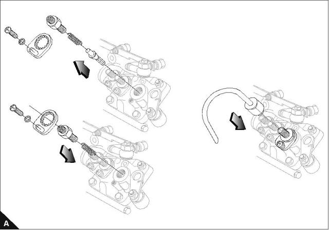
2 Disconnect or remove the ESOS, HP pipes and LP fuel inlet pipes from pump (A).
3 Ensure the throttle lever is held in the maximum fuel position after the procedure.
4 Remove the delivery valve holder for number 1 cylinder and remove the delivery valve. Store the delivery
valve in appropriate clean fuel until assembly.
Note: The fuel pump may need to be moved to an upright position to remove and to fit the delivery valves.
Continued
Workshop Manual, TPD 1377E, issue 4
85
This document has been printed from SPI². Not for Resale
![]()
![]()
![]()
![]()

8
100 Series
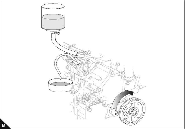
5 Connect a suitable tank, which has a tap and contains 0,2 litres (¼ pint) of clean fuel, to the pump inlet.
6 Connect the fuel pump spill pipe to the delivery valve holder for number 1 cylinder. Put a suitable waste fuel
container below the pipe neck and open the tap, if correctly set fuel should flow (B).
Note: The outlet from the tank should be approximately 152 mm (6 in) above the pump.
7 Turn the crankshaft slowly until the flow of fuel reduces to a drop which falls from pipe neck every 7-10
seconds. This is then the timing point.
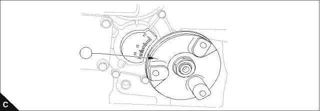
8 Use the value shown by the timing mark (C1) with the injection timing tables given in "Injection timing" on
page 15.
1
Continued
86
Workshop Manual, TPD 1377E, issue 4
This document has been printed from SPI². Not for Resale
![]()
![]()
8
100 Series
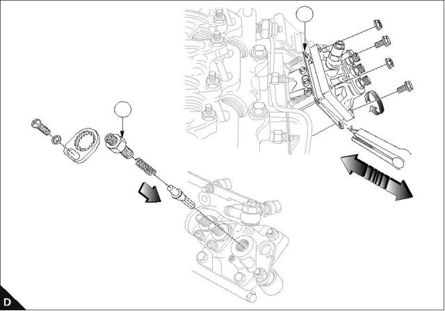
9 If engine timing is incorrect adjust the thickness of shim (D2) to correct.
Note: If the shim thickness is adjusted by 0,1 mm, the timing will alter by approximately one degree. An
increase in the number of shims will retard the timing, but if the number of shims are decreased this will
advance the timing.
10 Fit the delivery valve.
Notes:
Ensure that the delivery valve holder (D1) is tightened to the specified torque.
For emissions approved engines. If it is necessary to change the fuel injection pump, the fuel delivery must
be reset on a suitable test dynamometer with the new pump. The procedure above, on injection pump
timing explains how to change the timing.
When changing the timing, it is important that this procedure is done before the engine is tested on a
suitable dynamometer.
2
1
Workshop Manual, TPD 1377E, issue 4
87
This document has been printed from SPI². Not for Resale
![]()
![]()
![]()
![]()
![]()
This page is intentionally blank
This document has been printed from SPI². Not for Resale
9
100 Series
Aspiration system
9
Breather system
To clean and renew
Operation 9-1
Cautions:
Failure to change a damaged, blocked or restricted engine breather hose may cause a back pressure in
the crankcase, causing premature failure of the rear engine oil seal.
Do not start an engine that is found to have a damaged, blocked or restricted breather hose, starting the
engine may cause damage to the rear engine oil seal.
Special requirements
POWERPART products
Description
Part number
21826039
Platelock
Threadlock
21820119 or 21820118
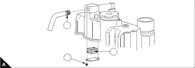
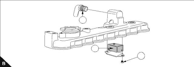
Clean the breather gauze (A2/B2) with suitable cleaning solvent. If damaged renew.
If the engine breather pipe (A1/B1) is damaged, blocked or restricted, it must be renewed.
On assembly, apply Powerpart Platelock to the threaded area on the breather pipes (A1/B1).
On assembly, apply Powerpart Threadlock to the threaded area on the setscrew (A3/B3).
102-05
103-07
103-10
1
2
3
103-13
103-15
104-19
104-22
1
2
33
Workshop Manual, TPD 1377E, issue 4
89
This document has been printed from SPI². Not for Resale
![]()
![]()
![]()
![]()
![]()
![]()

This page is intentionally blank
This document has been printed from SPI². Not for Resale
100 Series
10
Lubrication system
10
Oil filter canister
To remove and to fit
Operation 10-1
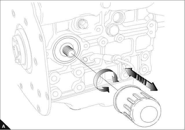
1 Remove the filter canister with a strap wrench or a similar tool and then discard the canister.
2 Clean the seal face of the filter head.
3 Lubricate the seal of the new canister with clean engine oil before assembly.
4 Install the new canister and tighten it by hand only. Do not use a strap wrench.
5 Tighten the canister by a further ½ to ¾ of a turn by hand only.
6 After the lubricating oil has been added to the sump, operate the engine and check for leakage from the
filter. When the engine has cooled, check the oil level on the dipstick and add oil to the sump, as necessary.
Caution: Do not use a strap wrench to tighten the filter canister.
Workshop Manual, TPD 1377E, issue 4
91
This document has been printed from SPI². Not for Resale
![]()
![]()
![]()
![]()
10
100 Series
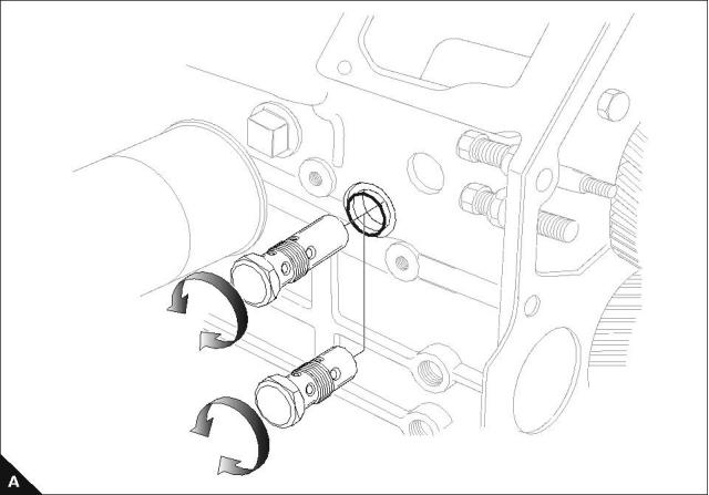
Pressure relief valve
To remove and to fit
Operation 10-2
Special requirements
Torque Nm (lbf ft) kgf m
Pressure relief valve
64 (47) 6,5
Renew the 'O' ring when the pressure relief valve is fitted to the cylinder block.
Caution: When the crankshaft is removed or fitted the pressure relief valve must be removed first.
102-05
103-07
103-10
103-13
103-15
104-19
104-22
92
Workshop Manual, TPD 1377E, issue 4
This document has been printed from SPI². Not for Resale
![]()
![]()
![]()
![]()
![]()
10
100 Series
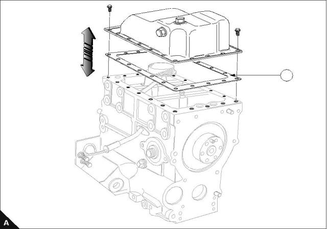
Lubricating oil sump
To remove and to fit
Operation 10-3
Special requirements
Torque Nm (lbf ft) kgf m
Sump setscrews
11 (8) 1,1
Note: When the sump is fitted renew the joint (A1).
1
Workshop Manual, TPD 1377E, issue 4
93
This document has been printed from SPI². Not for Resale
![]()
![]()
![]()
![]()
![]()
10
100 Series
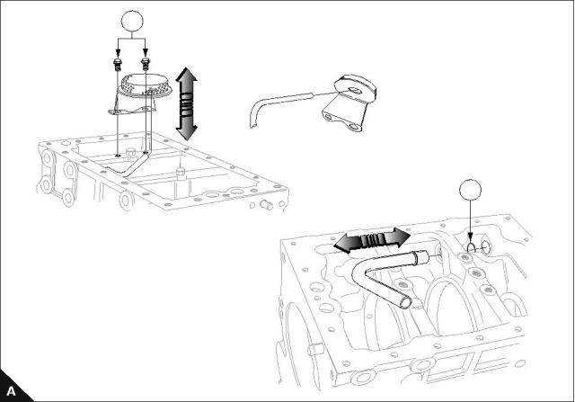
Strainer and suction pipe
To remove and to fit
Operation 10-4
Special requirements
Torque Nm (lbf ft) kgf m
Filter setscrews (A1)
11 (8) 1,1
Note: On assembly renew the 'O' ring (A2).
1
2
94
Workshop Manual, TPD 1377E, issue 4
This document has been printed from SPI². Not for Resale
![]()
![]()
![]()
![]()
![]()
10
100 Series
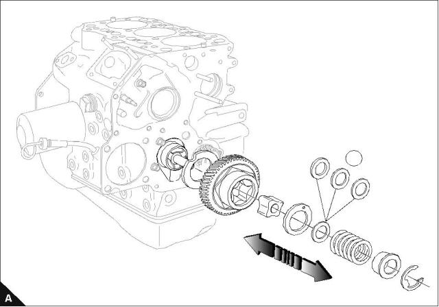
Lubricating oil pump
To remove, to fit and to inspect
Operation 10-5
For the tolerances see "Idler gear and oil pump" on page 75 and "Oil pump end float" on page 78.
Note: Extra shims (A1) may be needed to achieve the standard clearance.
1
Workshop Manual, TPD 1377E, issue 4
95
This document has been printed from SPI². Not for Resale
![]()
![]()
![]()
![]()
10
100 Series
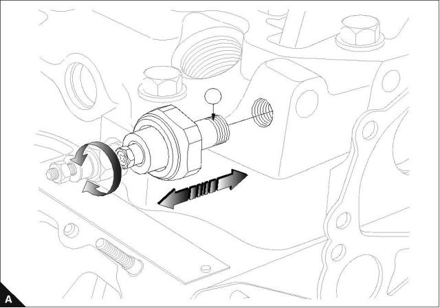
Oil pressure switch
To remove and to fit
Operation 10-6
Special requirements
POWERPART products
Torque Nm (lbf ft) kgf m
Description
Part number
Platelock
21826039
Oil pressure switch
11 (8) 1,1
Powerpart Platelock must be applied to the thread (A1) when the oil pressure switch is fitted to the cylinder
block.
Oil pressure switch range of operation 19,3 - 39,3 KPa (2.8-5.7 lbf/in²).
1
96
Workshop Manual, TPD 1377E, issue 4
This document has been printed from SPI². Not for Resale
![]()
![]()
![]()
![]()

100 Series
11
Fuel system
11
Atomisers
To remove
Operation 11-1
Cautions:
Deep sockets should always be used for this procedure.
Connections should be blanked off until assembly.
103-13
103-15
104-19
104-22
102-05
103-07
103-10
3
2
1
A
Workshop Manual, TPD 1377E, issue 4
97
This document has been printed from SPI². Not for Resale
![]()
![]()
![]()
![]()
![]()
![]()

11
100 Series
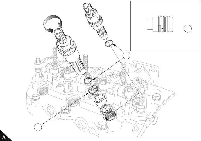
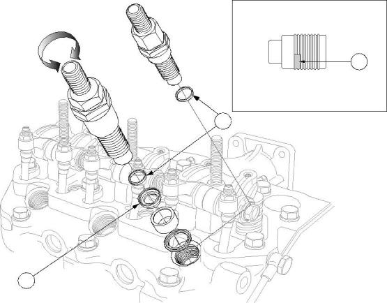
To fit
Operation 11-2
Special requirements
Torque Nm (lbf ft) kgf m
Test pressures kgf/cm² (lbf/in²) ats
102-05, 103-07
64 (47) 6,5
81 (60) 8,2
64 (47) 6,5
102-05, 103-07
120 (1707) 116
120 (1707) 116
150 (2133) 145
103-10
103-10
103-13, 103-15, 104-19, 104-22
103-13, 103-15, 104-19, 104-22
1 Clean and dry the male and female threads of the atomiser and the cylinder head.
2 Apply a 2 mm (0.08 in) bead of sealant POWERPART universal jointing compound, part number 1861117,
to extend 6 mm (0.24 in) along the first two threads of the atomiser (A3).
Engine serial numbers KR-----924551F to KR-----926370F require two nozzle washers (A2) fitted when
servicing any of the above engine serial numbers.
All 104-22 engines built from engine serial number KR-----926371F require one nozzle washer (A2) fitted when
servicing.
If a new cylinder head is fitted on engine serial numbers KR-----924551F to KR-----926370F then only one
nozzle washer (A2) is fitted.
Notes:
Item (A1) is used on 103-10 engine only.
Item (A2) is part number 131426200.
103-13
103-15
104-19
104-22
102-05
103-07
103-10
3
2
1
A
98
Workshop Manual, TPD 1377E, issue 4
This document has been printed from SPI². Not for Resale
![]()
![]()
![]()
![]()
![]()
![]()


11
100 Series
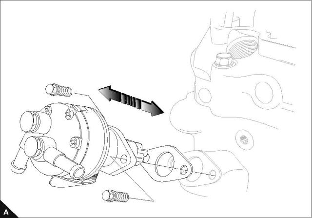
Fuel lift pump
To remove and to fit early fuel lift pump
Operation 11-3
Note: Camshaft eccentric must be in the maximum lift position for the priming lever to operate correctly.
Workshop Manual, TPD 1377E, issue 4
99
This document has been printed from SPI². Not for Resale
![]()
![]()
![]()
![]()
11
100 Series
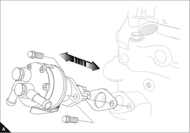
To remove and to fit the latest fuel lift pump
Operation 11-4
Engine
Torque Nm (lbf ft) kgf m
Lift pump setscrew
6 (4.4) 0,6
All models
Lift pump inlet adjusting bolt (A1)
2,5 (1.8) 0,25
The fuel inlet for the fuel lift pump can rotate 360° and is adjustable in 15° increments.
The fuel lift pump flange has two sets of locating holes this allows the pump to be fitted in four positions for the
outlet connection.
Note: Camshaft eccentric must be in the minimum lift position for the priming lever to operate correctly.
100
Workshop Manual, TPD 1377E, issue 4
This document has been printed from SPI². Not for Resale
![]()
![]()
![]()
![]()

11
100 Series
To dismantle and to assemble the early fuel lift pump
Operation 11-5
Workshop Manual, TPD 1377E, issue 4
101
This document has been printed from SPI². Not for Resale
免费热线
400-100-8969 15088860848
400-100-8969 15088860848
机组销售
0574-26871589 15267810868
0574-26871589 15267810868
配件销售
0574-26886646 15706865167
0574-26886646 15706865167
维修热线
0574-26871569 18658287286
0574-26871569 18658287286
手机端

微信公众号