 English
 Espaol
 Franais
 阿拉伯
阿拉伯 中文(简)
中文(简) Deutsch
 Italiano
 Português
 日本
日本 韩国
韩国 български
 hrvatski
 esky
esky Dansk
Dansk Nederlands
 suomi
suomi Ελληνικ
 印度
印度 norsk
norsk Polski
 Roman
Roman русский
 Svenska
 珀金斯403F-15T、404F-22、404F-22T柴油机维修操作保养,珀金斯403F-15T、404F-22、404F-22T柴油机维修操作保养技术支持中心,珀金斯403F-15T、404F-22、404F-22T柴油机维修操作保养代理商,珀金斯403F-15T、404F-22、404F-22T柴油机维修操作保养销售服务中心,珀金斯403F-15T、404F-22、404F-22T柴油机维修操作保养价格规格资料查询,宁波日昕动力科技有限公司

珀金斯403F-15T、404F-22、404F-22T柴油机维修操作保养一
详细描述
Operation and
Maintenance
Manual
403F-15T, 404F-22 and 404F-22T
Industrial Engines
EL (Engine)
EN (Engine)
EP (Engine)
This document is printed from SPI². Not for RESALE
![]()
![]()
![]()
![]()

Important Safety Information
Most accidents tha t involve produc t op eration, ma intena nc e and repair are caus ed by failure to
ob serve basic safety rules or precautions . An accident can often be avoided by recog nizing pote ntially
ha za rdous situations before an accident oc curs . A person mus t be alert to pote ntial ha za rds. This
person should also ha ve the ne cessary training, skills and tools to perform the se func tions properly.
Improper operation, lubrication, maintenance or repair of this product can be dangerous and
could result in injury or death.
Do not operate or perform any lubrication, maintenance or repair on this product, until you have
read and understood the operation, lubrication, maintenance and repair information.
Sa fety precautions and warning s are provided in this ma nua l and on the produc t. If the se ha za rd
warning s are not he eded, bod ily injury or death could oc cur to you or to othe r persons .
The ha za rds are identified by the “Safety Alert Symb ol” and followed by a “Signa l Word” suc h as
“DANGER”, “WARNING” or “CAUTION”. The Sa fety Alert “WARNING” label is shown below.
The me aning of this safety alert symb ol is as follows:
Attention! Become Alert! Your Safety is Involved.
The me ssage tha t appears und er the warning explains the ha za rd and can be either written or
pictorially presente d.
Op erations tha t ma y caus e produc t dama ge are identified by “NOTICE” labels on the produc t and in
this pub lication.
Perkins cannot anticipate every possible circumstance that might involve a potential hazard. The
warnings in this publication and on the product are, therefore, not all inclusive. If a tool, procedure,
work method or operating technique that is not specifically recommended by Perkins is used,
you must satisfy yourself that it is safe for you and for others. You should also ensure that the
product will not be damaged or be made unsafe by the operation, lubrication, maintenance or
repair procedures that you choose.
The informa tion, specifications , and illustrations in this pub lication are on the basis of informa tion tha t
was available at the time tha t the pub lication was written. The specifications , torque s, pressure s,
me asure me nts , adjustme nts , illustrations , and othe r items can cha ng e at any time. These cha ng es can
affect the service tha t is given to the produc t. Ob tain the comp lete and mos t current informa tion before
you start any job. Pe rkins dealers or Pe rkins distributors ha ve the mos t current informa tion available.
When replacement parts are required for this
product Perkins recommends using Perkins
replacement parts.
Failure to heed this warning can lead to prema-
ture failures, product damage, personal injury or
death.
This document is printed from SPI². Not for RESALE
![]()
![]()
SEBU8609
3
Table of Contents
Table of Contents
Refill Capacities....................... ....................... 57
Maintenance Recommendations.......... .......... 70
Maintenance Interval Schedule........... ........... 73
Warranty Section
Foreword.............................. ............................. 4
Safety Section
Safety Messages....................... ....................... 5
General Hazard Information............... .............. 5
Burn Prevention........................ ........................ 9
Fire Prevention and Explosion Prevention ... .. 10
Crushing Prevention and Cutting Prevention . .11
Mounting and Dismounting............... .............. 12
Before Starting Engine ................. .................. 12
Engine Starting........................ ....................... 12
Engine Stopping....................... ...................... 13
Electrical System...................... ...................... 13
Engine Electronics..................... ..................... 14
Product Information Section
Warranty Information................... ................... 99
Reference Information Section
Reference Materials .................. ................... 103
Index Section
Index............................... .............................. 104
General Information.................... .................... 15
Product Identification Information.......... ......... 26
Operation Section
Lifting and Storage..................... ..................... 28
Features and Controls.................. .................. 30
Engine Diagnostics..................... .................... 43
Engine Starting........................ ....................... 45
Engine Operation...................... ...................... 48
Cold Weather Operation................. ................ 52
Engine Stopping....................... ...................... 56
Maintenance Section
This document is printed from SPI². Not for RESALE
![]()
4
SEBU8609
Foreword
Foreword
Recommended service should be performed at the
appropriate intervals as indicated in the Maintenance
Interval Schedule. The actual operating environment
of the engine also governs the Maintenance Interval
Schedule. Therefore, under extremely severe, dusty,
wet or freezing cold operating conditions, more
frequent lubrication and maintenance than is
specified in the Maintenance Interval Schedule may
be necessary.
Literature Information
This manual contains safety, operation instructions,
lubrication and maintenance information. This manual
should be stored in or near the engine area in a
literature holder or literature storage area. Read,
study and keep it with the literature and engine
information.
The maintenance schedule items are organized for a
preventive maintenance management program. If the
preventive maintenance program is followed, a
periodic tune-up is not required. The implementation
of a preventive maintenance management program
should minimize operating costs through cost
avoidances resulting from reductions in unscheduled
downtime and failures.
English is the primary language for all Perkins
publications. The English used facilitates translation
and consistency.
Some photographs or illustrations in this manual
show details or attachments that may be different
from your engine. Guards and covers may have been
removed for illustrative purposes. Continuing
improvement and advancement of product design
may have caused changes to your engine which are
not included in this manual. Whenever a question
arises regarding your engine, or this manual, please
consult with your Perkins dealer or your Perkins
distributor for the latest available information.
Maintenance Intervals
Perform maintenance on items at multiples of the
original requirement. We recommend that the
maintenance schedules be reproduced and displayed
near the engine as a convenient reminder. We also
recommend that a maintenance record be maintained
as part of the engine's permanent record.
Safety
Your authorized Perkins dealer or your Perkins
distributor can assist you in adjusting your
maintenance schedule to meet the needs of your
operating environment.
This safety section lists basic safety precautions. In
addition, this section identifies hazardous, warning
situations. Read and understand the basic
precautions listed in the safety section before
operating or performing lubrication, maintenance and
repair on this product.
Overhaul
Major engine overhaul details are not covered in the
Operation and Maintenance Manual except for the
interval and the maintenance items in that interval.
Major repairs should only be carried out by Perkins
authorized personnel. Your Perkins dealer or your
Perkins distributor offers a variety of options
regarding overhaul programs. If you experience a
major engine failure, there are also numerous after
failure overhaul options available. Consult with your
Perkins dealer or your Perkins distributor for
information regarding these options.
Operation
Operating techniques outlined in this manual are
basic. They assist with developing the skills and
techniques required to operate the engine more
efficiently and economically. Skill and techniques
develop as the operator gains knowledge of the
engine and its capabilities.
The operation section is a reference for operators.
Photographs and illustrations guide the operator
through procedures of inspecting, starting, operating
and stopping the engine. This section also includes a
discussion of electronic diagnostic information.
California Proposition 65 Warning
Diesel engine exhaust and some of its constituents
are known to the State of California to cause cancer,
birth defects, and other reproductive harm. Battery
posts, terminals and related accessories contain lead
and lead compounds. Wash hands after handling.
Maintenance
The maintenance section is a guide to engine care.
The illustrated, step-by-step instructions are grouped
by service hours and/or calendar time maintenance
intervals. Items in the maintenance schedule are
referenced to detailed instructions that follow.
This document is printed from SPI². Not for RESALE
![]()
SEBU8609
5
Safety Section
Safety Messages
Safety Section
Do not operate or work on this equipment unless
you have read and understand the instructions
and warnings in the Operation and Maintenance
Manuals. Failure to follow the instructions or heed
the warnings could result in serious injury or
death.
i05139549
Safety Messages
There may be several specific warning signs on your
engine. The exact location and a description of the
warning signs are reviewed in this section. Become
familiar with all warning signs.
Ensure that all of the warning signs are legible. Clean
the warning signs or replace the warning signs if the
words cannot be read or if the illustrations are not
visible. Use a cloth, water, and soap to clean the
warning signs. Do not use solvents, gasoline, or other
harsh chemicals. Solvents, gasoline, or harsh
chemicals could loosen the adhesive that secures the
warning signs. The warning signs that are loosened
could drop off the engine.
Replace any warning sign that is damaged or
missing. If a warning sign is attached to a part of the
engine that is replaced, install a new warning sign on
the replacement part. Your Perkins dealer or your
distributor can provide new warning signs.
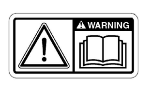
Illustration 2
g01154807
Typical example
(1) Universal Warning
The location of the universal warning label is located
on the right side of the valve mechanism cover.
i05139571
General Hazard Information
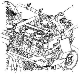
Illustration 1
g03256898
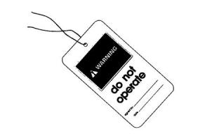
Illustration 3
g00104545
(1) Universal Warning
Attach a “Do Not Operate” warning tag or a similar
warning tag to the start switch or to the controls
before you service the equipment or before you repair
the equipment.
This document is printed from SPI². Not for RESALE
![]()
![]()
![]()
![]()
![]()
![]()
![]()
![]()
![]()
6
SEBU8609
Safety Section
General Hazard Information
• Tampering with the engine installation or tampering
with the OEM supplied wiring can be dangerous.
Personal injury, death and/or engine damage
could result.
• The engine is stopped. Ensure that the engine
cannot be started.
• The protective locks or the controls are in the
applied position.
• Vent the engine exhaust to the outside when the
engine is operated in an enclosed area.
• Engage the secondary brakes or parking brakes.
• Block the vehicle or restrain the vehicle before
maintenance or repairs are performed.
• If the engine is not running, do not release the
secondary brake or the parking brake systems
unless the vehicle is blocked or unless the vehicle
is restrained.
• Disconnect the batteries when maintenance is
performed or when the electrical system is
serviced. Disconnect the battery ground leads.
Tape the leads in order to help prevent sparks.
• Wear a hard hat, protective glasses, and other
protective equipment, as required.
• Do not attempt any repairs or any adjustments to
the engine while the engine is operating.
• When work is performed around an engine that is
operating, wear protective devices for ears in order
to help prevent damage to hearing.
• Do not attempt any repairs that are not
understood. Use the proper tools. Replace any
equipment that is damaged or repair the
equipment.
• Do not wear loose clothing or jewelry that can snag
on controls or on other parts of the engine.
• Ensure that all protective guards and all covers are
secured in place on the engine.
• For initial start-up of a new engine or for starting an
engine that has been serviced, make provisions to
stop the engine if an overspeed occurs. The
stopping of the engine may be accomplished by
shutting off the fuel supply and/or the air supply to
the engine. Ensure that only the fuel supply line is
shut off. Ensure that the fuel return line is open.
• Never put maintenance fluids into glass
containers. Glass containers can break.
• Use all cleaning solutions with care.
• Report all necessary repairs.
• Start the engine from the operators station (cab).
Never short across the starting motor terminals or
the batteries. This action could bypass the engine
neutral start system and/or the electrical system
could be damaged.
Unless other instructions are provided, perform the
maintenance under the following conditions:
Illustration 4
g00702020
Wear a hard hat, protective glasses, and other
protective equipment, as required.
Do not wear loose clothing or jewelry that can snag
on controls or on other parts of the engine.
Make sure that all protective guards and all covers
are secured in place on the engine.
This document is printed from SPI². Not for RESALE
![]()

![]()
![]()
SEBU8609
7
Safety Section
General Hazard Information
Keep the engine free from foreign material. Remove
debris, oil, tools, and other items from the deck, from
walkways, and from steps.
Never put maintenance fluids into glass containers.
Drain all liquids into a suitable container.
Obey all local regulations for the disposal of liquids.
Use all cleaning solutions with care.
Report all necessary repairs.
Do not allow unauthorized personnel on the
equipment.
Ensure that the power supply is disconnected before
you work on the bus bar or the glow plugs.
Illustration 5
g00687600
Perform maintenance on the engine with the
equipment in the servicing position. Refer to the OEM
information for the procedure for placing the
equipment in the servicing position.
Always use a board or cardboard when you check for
a leak. Leaking fluid that is under pressure can
penetrate body tissue. Fluid penetration can cause
serious injury and possible death. A pin hole leak can
cause severe injury. If fluid is injected into your skin,
you must get treatment immediately. Seek treatment
from a doctor that is familiar with this type of injury.
Pressure Air and Water
Pressurized air and/or water can cause debris and/or
hot water to be blown out. This could result in
personal injury.
Containing Fluid Spillage
Care must be taken in order to ensure that fluids are
contained during performance of inspection,
maintenance, testing, adjusting, and repair of the
engine. Make provision to collect the fluid with a
suitable container before any compartment is opened
or before any component is disassembled.
The direct application of pressurized air or
pressurized water to the body could result in personal
injury.
When pressurized air and/or water is used for
cleaning, wear protective clothing, protective shoes,
and eye protection. Eye protection includes goggles
or a protective face shield.
• Only use the tools that are suitable for collecting
fluids and equipment that is suitable for collecting
fluids.
The maximum air pressure for cleaning purposes
must be below 205 kPa (30 psi). The maximum water
pressure for cleaning purposes must be below
275 kPa (40 psi).
• Only use the tools that are suitable for containing
fluids and equipment that is suitable for containing
fluids.
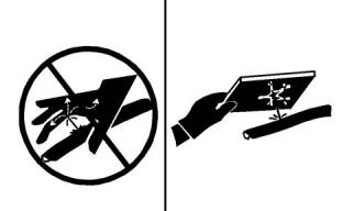
Fluid Penetration
Obey all local regulations for the disposal of liquids.
Pressure can be trapped in the hydraulic circuit long
after the engine has been stopped. The pressure can
cause hydraulic fluid or items such as pipe plugs to
escape rapidly if the pressure is not relieved correctly.
Do not remove any hydraulic components or parts
until pressure has been relieved or personal injury
may occur. Do not disassemble any hydraulic
components or parts until pressure has been relieved
or personal injury may occur. Refer to the OEM
information for any procedures that are required to
relieve the hydraulic pressure.
This document is printed from SPI². Not for RESALE
![]()
![]()
![]()
8
SEBU8609
Safety Section
General Hazard Information
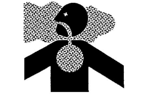
Inhalation
• Never use compressed air for cleaning.
• Avoid brushing materials that contain asbestos.
• Avoid grinding materials that contain asbestos.
• Use a wet method in order to clean up asbestos
materials.
• A vacuum cleaner that is equipped with a high
efficiency particulate air filter (HEPA) can also be
used.
• Use exhaust ventilation on permanent machining
jobs.
• Wear an approved respirator if there is no other
way to control the dust.
Illustration 6
g00702022
• Comply with applicable rules and regulations for
the work place. In the United States , use
Occupational Safety and Health Administration
(OSHA) requirements. These OSHA
Exhaust
Use caution. Exhaust fumes can be hazardous to
health. If you operate the equipment in an enclosed
area, adequate ventilation is necessary.
requirements can be found in 29 CFR 1910.1001.
• Obey environmental regulations for the disposal of
asbestos.
Asbestos Information
• Stay away from areas that might have asbestos
particles in the air.
Perkins equipment and replacement parts that are
shipped from Perkins are asbestos free. Perkins
recommends the use of only genuine Perkins
replacement parts. Use the following guidelines when
you handle any replacement parts that contain
asbestos or when you handle asbestos debris.
Dispose of Waste Properly
Use caution. Avoid inhaling dust that might be
generated when you handle components that contain
asbestos fibers. Inhaling this dust can be hazardous
to your health. The components that may contain
asbestos fibers are brake pads, brake bands, lining
material, clutch plates, and some gaskets. The
asbestos that is used in these components is usually
bound in a resin or sealed in some way. Normal
handling is not hazardous unless airborne dust that
contains asbestos is generated.
If dust that may contain asbestos is present, there are
several guidelines that should be followed:
Illustration 7
g00706404
Improperly disposing of waste can threaten the
environment. Potentially harmful fluids should be
disposed of according to local regulations.
Always use leakproof containers when you drain
fluids. Do not pour waste onto the ground, down a
drain, or into any source of water.
This document is printed from SPI². Not for RESALE
![]()
![]()
![]()

![]()
![]()
SEBU8609
9
Safety Section
Burn Prevention
i05200861
Coolant
Burn Prevention
When the engine is at operating temperature, the
engine coolant is hot. The coolant is also under
pressure. The radiator and all lines to the heaters or
to the engine contain hot coolant.
Do not touch any part of an operating engine system.
The engine, the exhaust, and the engine
aftertreatmentsystem can reach temperatures as
high as 650 °C (1202 °F) under normal operating
conditions.
Any contact with hot coolant or with steam can cause
severe burns. Allow cooling system components to
cool before the cooling system is drained.
Check that the coolant level after the engine has
stopped and the engine has been allowed to cool.
At idle engine speed and/or zero vehicle speed, an
operator can request a manual regeneration. Under
this condition, the exhaust gas temperature can reach
650 °C (1202 °F). Otherwise automatic regeneration
can produce exhaust gas temperatures as high as
650 °C (1202 °F).
Ensure that the filler cap is cool before removing the
filler cap. The filler cap must be cool enough to touch
with a bare hand. Remove the filler cap slowly in
order to relieve pressure.
Cooling system conditioner contains alkali. Alkali can
cause personal injury. Do not allow alkali to contact
the skin, the eyes, or the mouth.
Allow the engine system to cool before any
maintenance is performed. Relieve all pressure in the
following systems, hydraulic system, lubrication
system, fuel system, and the cooling system before
related items are disconnected.
Oils
Hot oil and hot lubricating components can cause
personal injury. Do not allow hot oil to contact the
skin. Also, do not allow hot components to contact the
skin.
Contact with high pressure fuel may cause fluid
penetration and burn hazards. High pressure fuel
spray may cause a fire hazard. Failure to follow
these inspection, maintenance and service in-
structions may cause personal injury or death.
Batteries
Electrolyte is an acid. Electrolyte can cause personal
injury. Do not allow electrolyte to contact the skin or
the eyes. Always wear protective glasses for
servicing batteries. Wash hands after touching the
batteries and connectors. Use of gloves is
recommended.
After the engine has stopped, allow if active the
regeneration active lamp to be extinguished before
any service or repair is performed.
Induction System
Sulfuric Acid Burn Hazard may cause serious per-
sonal injury or death.
The exhaust gas cooler may contain a small
amount of sulfuric acid. The use of fuel with sulfur
levels greater than 15 ppm may increase the
amount of sulfuric acid formed. The sulfuric acid
may spill from the cooler during service of the en-
gine. The sulfuric acid will burn the eyes, skin and
clothing on contact. Always wear the appropriate
personal protective equipment (PPE) that is noted
on a material safety data sheet (MSDS) for sulfuric
acid. Always follow the directions for first aid that
are noted on a material safety data sheet (MSDS)
for sulfuric acid.
This document is printed from SPI². Not for RESALE
![]()
![]()
![]()
![]()
![]()
10
SEBU8609
Safety Section
Fire Prevention and Explosion Prevention
i04047444
Do not weld on lines or tanks that contain flammable
fluids. Do not flame cut lines or tanks that contain
flammable fluid. Clean any such lines or tanks
thoroughly with a nonflammable solvent prior to
welding or flame cutting.
Fire Prevention and Explosion
Prevention
Wiring must be kept in good condition. Ensure that all
electrical wires are correctly routed and securely
attached. Check all electrical wires daily. Repair any
wires that are loose or frayed before you operate the
engine. Clean all electrical connections and tighten all
electrical connections.
Eliminate all wiring that is unattached or unnecessary.
Do not use any wires or cables that are smaller than
the recommended gauge. Do not bypass any fuses
and/or circuit breakers.
Arcing or sparking could cause a fire. Secure
connections, recommended wiring, and correctly
maintained battery cables will help to prevent arcing
or sparking.
Ensure that the engine is stopped. Inspect all lines
and hoses for wear or for deterioration. The hoses
must be correctly routed. The lines and hoses must
have adequate support and secure clamps.
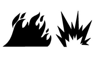
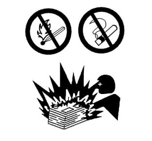
Illustration 8
g00704000
All fuels, most lubricants, and some coolant mixtures
are flammable.
Oil filters and fuel filters must be correctly installed.
The filter housings must be tightened to the correct
torque. Refer to the Disassembly and Assembly
manual for more information.
Flammable fluids that are leaking or spilled onto hot
surfaces or onto electrical components can cause a
fire. Fire may cause personal injury and property
damage.
After the emergency stop button has been operated,
ensure that you allow 15 minutes, before the engine
covers are removed.
Determine whether the engine will be operated in an
environment that allows combustible gases to be
drawn into the air inlet system. These gases could
cause the engine to overspeed. Personal injury,
property damage, or engine damage could result.
If the application involves the presence of
combustible gases, consult your Perkins dealer and/
or your Perkins distributor for additional information
about suitable protection devices.
Remove all flammable combustible materials or
conductive materials such as fuel, oil, and debris from
the engine. Do not allow any flammable combustible
materials or conductive materials to accumulate on
the engine.
Store fuels and lubricants in correctly marked
containers away from unauthorized persons. Store
oily rags and any flammable materials in protective
containers. Do not smoke in areas that are used for
storing flammable materials.
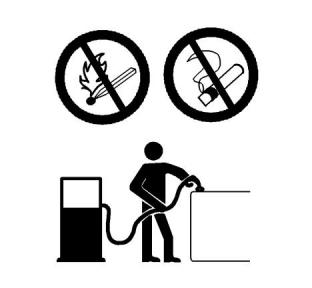
Illustration 9
g00704059
Use caution when you are refueling an engine. Do not
smoke while you are refueling an engine. Do not
refuel an engine near open flames or sparks. Always
stop the engine before refueling.
Do not expose the engine to any flame.
Exhaust shields (if equipped) protect hot exhaust
components from oil or fuel spray in case of a line, a
tube, or a seal failure. Exhaust shields must be
installed correctly.
This document is printed from SPI². Not for RESALE
![]()
![]()
![]()
![]()
![]()
SEBU8609
11
Safety Section
Crushing Prevention and Cutting Prevention
• High-pressure fuel line or lines are removed.
• End fittings are damaged or leaking.
• Outer coverings are chafed or cut.
• Wires are exposed.
• Outer coverings are ballooning.
• Flexible parts of the hoses are kinked.
• Outer covers have embedded armoring.
• End fittings are displaced.
Make sure that all clamps, guards, and heat shields
are installed correctly. During engine operation,
correct installation will help to prevent vibration,
rubbing against other parts, and excessive heat.
Regeneration
The exhaust gas temperature during regeneration will
be elevated. Follow proper fire prevention instructions
and use the disable switch function when appropriate.
Illustration 10
g00704135
Gases from a battery can explode. Keep any open
flames or sparks away from the top of a battery. Do
not smoke in battery charging areas.
i02143194
Never check the battery charge by placing a metal
object across the terminal posts. Use a voltmeter or a
hydrometer.
Crushing Prevention and
Cutting Prevention
Incorrect jumper cable connections can cause an
explosion that can result in injury. Refer to the
Operation Section of this manual for specific
instructions.
Support the component correctly when work beneath
the component is performed.
Do not charge a frozen battery. Charge a frozen
battery may cause an explosion.
Unless other maintenance instructions are provided,
never attempt adjustments while the engine is
running.
The batteries must be kept clean. The covers (if
equipped) must be kept on the cells. Use the
recommended cables, connections, and battery box
covers when the engine is operated.
Stay clear of all rotating parts and of all moving parts.
Leave the guards in place until maintenance is
performed. After the maintenance is performed,
reinstall the guards.
Fire Extinguisher
Keep objects away from moving fan blades. The fan
blades will throw objects or cut objects.
Make sure that a fire extinguisher is available. Be
familiar with the operation of the fire extinguisher.
Inspect the fire extinguisher and service the fire
extinguisher regularly. Obey the recommendations on
the instruction plate.
When objects are struck, wear protective glasses in
order to avoid injury to the eyes.
Chips or other debris may fly off objects when objects
are struck. Before objects are struck, ensure that no
one will be injured by flying debris.
Lines, Tubes, and Hoses
Do not bend high-pressure lines. Do not strike high-
pressure lines. Do not install any lines that are
damaged.
Leaks can cause fires. Consult your Perkins dealer
or your Perkins distributor for replacement parts.
Replace the parts if any of the following conditions
are present:
This document is printed from SPI². Not for RESALE
![]()
![]()
![]()
12
SEBU8609
Safety Section
Mounting and Dismounting
i04016709
i02157354
Mounting and Dismounting
Engine Starting
Do not climb on the engine or the engine
aftertreatment.The engine and aftertreatment have
not been designed with mounting or dismounting
locations.
Do not use aerosol types of starting aids such as
ether. Such use could result in an explosion and
personal injury.
Refer to the OEM for the location of foot and hand
holds for your specific application.
If a warning tag is attached to the engine start switch
or to the controls, DO NOTstart the engine or move
the controls. Consult with the person that attached
the warning tag before the engine is started.
i02813489
Before Starting Engine
All protective guards and all protective covers must
be installed if the engine must be started in order to
perform service procedures. To help prevent an
accident that is caused by parts in rotation, work
around the parts carefully.
Before the initial start-up of an engine that is new,
serviced or repaired, make provision to shut the
engine off, in order to stop an overspeed. This may
be accomplished by shutting off the air and/or fuel
supply to the engine.
Start the engine from the operator's compartment or
from the engine start switch.
Overspeed shutdown should occur automatically for
engines that are controlled electronically. If automatic
shutdown does not occur, press the emergency stop
button in order to cut the fuel and/or air to the engine.
Always start the engine according to the procedure
that is described in the Operation and Maintenance
Manual, “Engine Starting” topic in the Operation
Section. Knowing the correct procedure will help to
prevent major damage to the engine components.
Knowing the procedure will also help to prevent
personal injury.
Inspect the engine for potential hazards.
Before starting the engine, ensure that no one is on,
underneath, or close to the engine. Ensure that the
area is free of personnel.
To ensure that the jacket water heater (if equipped)
and/or the lube oil heater (if equipped) is working
correctly, check the water temperature gauge and the
oil temperature gauge during the heater operation.
If equipped, ensure that the lighting system for the
engine is suitable for the conditions. Ensure that all
lights work correctly, if equipped.
All protective guards and all protective covers must
be installed if the engine must be started in order to
perform service procedures. To help prevent an
accident that is caused by parts in rotation, work
around the parts carefully.
Engine exhaust contains products of combustion
which can be harmful to your health. Always start the
engine and operate the engine in a well ventilated
area. If the engine is started in an enclosed area, vent
the engine exhaust to the outside.
Do not bypass the automatic shutoff circuits. Do not
disable the automatic shutoff circuits. The circuits are
provided in order to help prevent personal injury. The
circuits are also provided in order to help prevent
engine damage.
Note: The engine is equipped with an automatic
device for cold starting for normal conditions of
operation. If the engine will be operated in very cold
conditions, then an extra cold starting aid may be
required. Normally, the engine will be equipped with
the correct type of starting aid for your region of
operation.
See the Service Manual for repairs and for
adjustments.
The 400 Series engines are equipped with a glow
plug starting aid in each individual cylinder that heats
the intake air in order to improve starting.
This document is printed from SPI². Not for RESALE
![]()
![]()
![]()
SEBU8609
13
Safety Section
Engine Stopping
i02234873
Grounding Practices
Engine Stopping
Stop the engine according to the procedure in the
Operation and Maintenance Manual, “Engine
Stopping (Operation Section)” in order to avoid
overheating of the engine and accelerated wear of
the engine components.
Use the Emergency Stop Button (if equipped) ONLY
in an emergency situation. Do not use the Emergency
Stop Button for normal engine stopping. After an
emergency stop, DO NOTstart the engine until the
problem that caused the emergency stop has been
corrected.
Stop the engine if an overspeed condition occurs
during the initial start-up of a new engine or an engine
that has been overhauled.
To stop an electronically controlled engine, cut the
power to the engine and/or shutting off the air supply
to the engine.
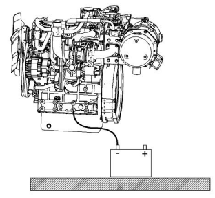
Illustration 11
g02324975
Typical example
Ground to battery
i04047709
Electrical System
Never disconnect any charging unit circuit or battery
circuit cable from the battery when the charging unit is
operating. A spark can cause the combustible gases
that are produced by some batteries to ignite.
To help prevent sparks from igniting combustible
gases that are produced by some batteries, the
negative “−” cable should be connected last from the
external power source to the primary position for
grounding.
Check the electrical wires daily for wires that are
loose or frayed. Tighten all loose electrical
connections before the engine is started. Repair all
frayed electrical wires before the engine is started.
See the Operation and Maintenance Manual for
specific starting instructions.
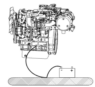
Illustration 12
g02324976
Typical example
Alternate ground to battery
Correct grounding for the engine electrical system is
necessary for optimum engine performance and
reliability. Incorrect grounding will result in
uncontrolled electrical circuit paths and in unreliable
electrical circuit paths.
This document is printed from SPI². Not for RESALE
![]()
![]()
![]()
![]()
![]()
14
SEBU8609
Safety Section
Engine Electronics
Uncontrolled electrical circuit paths can result in
damage to the crankshaft bearing journal surfaces
and to aluminum components.
The Engine Monitoring package can vary for different
engine models and different engine applications.
However, the monitoring system and the engine
monitoring control will be similar for all engines.
Engines that are installed without engine-to-frame
ground straps can be damaged by electrical
discharge.
Note: Many of the engine control systems and
display modules that are available for Perkins
Engines will work in unison with the Engine
Monitoring System. Together, the two controls will
provide the engine monitoring function for the specific
engine application. Refer to the Troubleshooting for
more information on the Engine Monitoring System.
To ensure that the engine and the engine electrical
systems function correctly, an engine-to-frame
ground strap with a direct path to the battery must be
used. This path may be provided by way of a direct
engine ground to the frame.
The connections for the grounds should be tight and
free of corrosion. The engine alternator must be
grounded to the negative “-” battery terminal with a
wire that is adequate to handle the full charging
current of the alternator.
The power supply connections and the ground
connections for the engine electronics should always
be from the isolator to the battery.
i05181812
Engine Electronics
Tampering with the electronic system installation
or the OEM wiring installation can be dangerous
and could result in personal injury or death and/or
engine damage.
This engine has a comprehensive, programmable
Engine Monitoring System. The Electronic Control
Module (ECM) has the ability to monitor the engine
operating conditions. If any of the engine parameters
extend outside an allowable range, the ECM will
initiate an immediate action.
The following actions are available for engine
monitoring control:
• Warning
• Derate
• Shutdown
The following monitored engine operating conditions
and components have the ability to limit engine speed
and/or the engine power:
• Oil Pressure Switch
• Coolant Temperature Sensor
• Engine Aftertreatment System
This document is printed from SPI². Not for RESALE
![]()
![]()
![]()
SEBU8609
15
,,Product Information Section
Model View Illustrations
Product Information
Section
General Information
i05139695
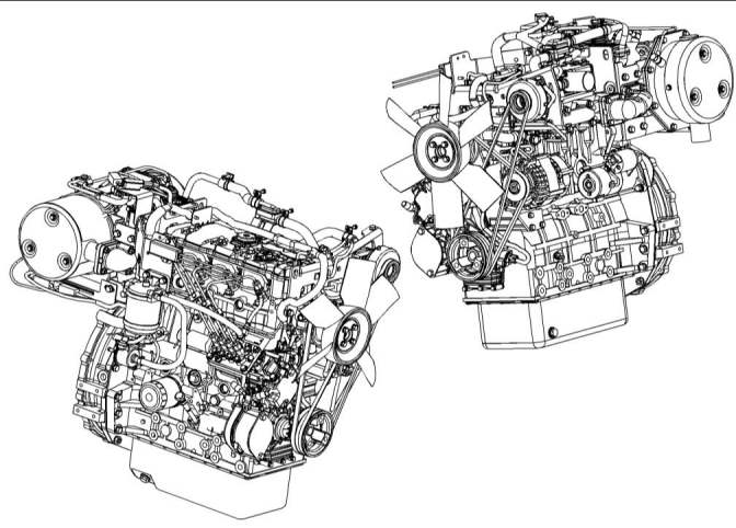
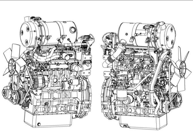
Model View Illustrations
(Engines and Aftertreatment)
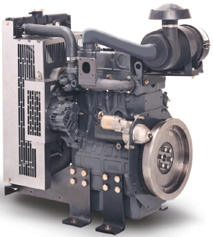
The following model views show typical features of
the engine. Due to individual applications, your
engine may appear different from the illustrations.
403F-15T
Illustration 13
g03246538
Typical example
This document is printed from SPI². Not for RESALE
![]()
![]()
16
SEBU8609
General Information
Model View Illustrations
404F-22
Illustration 14
g03246558
Typical example
This document is printed from SPI². Not for RESALE
![]()
![]()
SEBU8609
17
General Information
Model View Illustrations
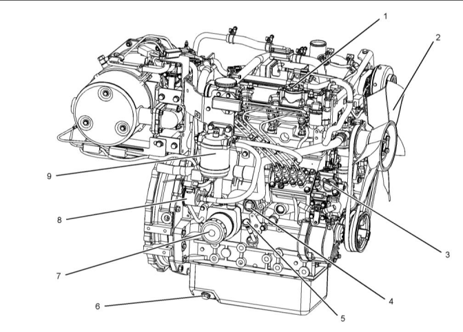
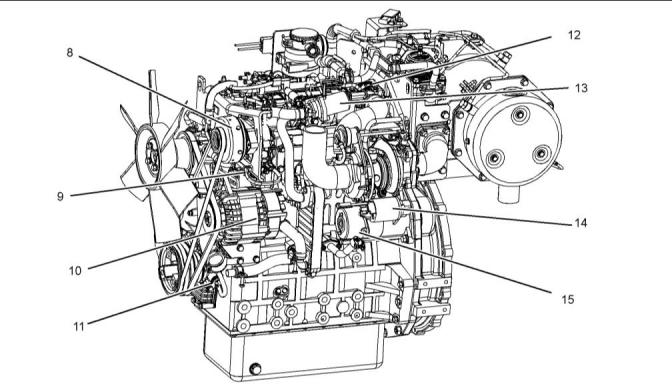
404F-22T
Illustration 15
g03246676
(1) Top oil filler
(2) Fan
(3) Side oil filler
(4) Cylinder block drain plug
(5) Oil gauge (Dipstick)
(6) Rear oil drain plug
(7) Oil filter
(8) Electric fuel pump
(9) Secondary fuel filter
This document is printed from SPI². Not for RESALE
![]()
![]()
18
SEBU8609
General Information
Model View Illustrations
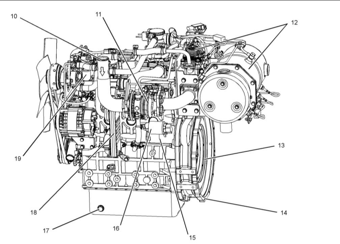
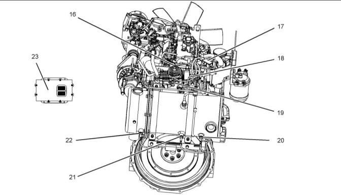
Illustration 16
g03246563
(10) Air intake
(14) Flywheel housing
(15) Starting motor
(16) Solenoid for starting motor
(17) Front oil drain plug
(18) NOx reduction system cooler
(19) Coolant outlet
(11) Turbocharger
(12) Aftertreatment system
(13) Flywheel
This document is printed from SPI². Not for RESALE
![]()
![]()
SEBU8609
19
General Information
Model View Illustrations
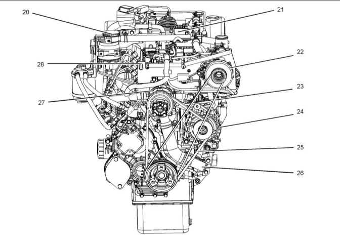
Illustration 17
g03249056
(20) Engine crankcase breather
(21) Rear lifting eye bracket
(22) Air pump
(23) Air pump drive belt
(24) Alternator
(25) Fan and alternator drive belt
(26) Coolant intake
(27) Water pump
(28) Front lifting eye
This document is printed from SPI². Not for RESALE
![]()
![]()
20
SEBU8609
General Information
Model View Illustrations
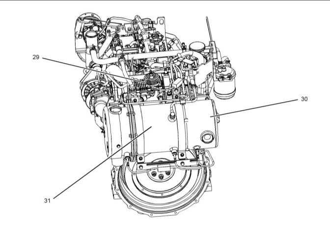
AftertreatmentSystem
Illustration 18
g03249241
(29) Aftertreatment Regeneration Device
(ARD), also known as the (Burner)
(30) Diesel Oxidation Catalyst (DOC)
(31) Diesel Particulate Filter (DPF)
This document is printed from SPI². Not for RESALE
![]()
![]()
SEBU8609
21
General Information
Model View Illustrations
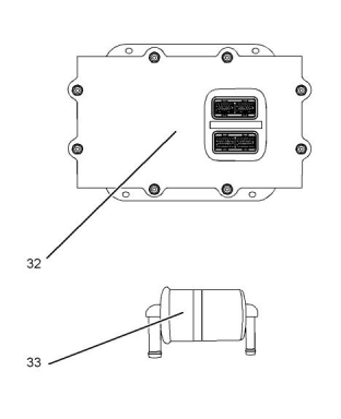
Off Engine Parts
Illustration 19
g03271819
(32) Electronic Control Unit (ECM)
(33) In line fuel filter
This document is printed from SPI². Not for RESALE
![]()
![]()
![]()
22
SEBU8609
General Information
Product Description
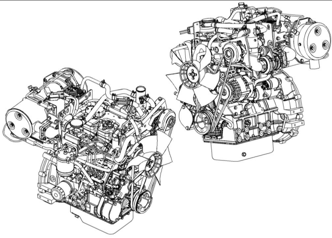
Engine with Low Mounted Air Pump
Illustration 20
g03321871
i05139813
The crankshaft for a three cylinder engine has four
main bearing journals. The crankshaft for a four
cylinder engine has five main bearing journals. End
play is controlled by the thrust washers that are
located on the rear main bearing.
Product Description
The 400F models are indirect injection engines. The
fuel injection pump is operated by a solenoid that is
controlled by a Pulse Width Modulation (PWM) signal
from the ECM.
The timing gears are stamped with timing marks in
order to ensure the correct assembly of the gears.
With the timing marks on the crankshaft gear
camshaft gear and the idler gear aligned No. 1 piston
will be at top center compression stroke.
The cylinder head assembly has one inlet valve and
one exhaust valve for each cylinder. Each cylinder
valve has a single valve spring.
The crankshaft gear turns the idler gear which then
turns the camshaft gear and the gear for the engine
oil pump.
The pistons have two compression rings and an oil
control ring. It is important to ensure the correct piston
height so that the piston does not contact the cylinder
head. The correct piston height also ensures efficient
combustion of fuel that is necessary in order to
conform to requirements for emissions.
The fuel injection pump is mounted in the cylinder
block. The fuel injection pump is operated by the
camshaft. The fuel pump is located on the right-hand
side of the cylinder block. The fuel pump is electrically
operated.
This document is printed from SPI². Not for RESALE
![]()
![]()
SEBU8609
23
General Information
Product Description
The fuel injection pump conforms to requirements for
emissions. If any adjustments to the fuel injection
pump timing and high idle are required, you must
refer to your Perkins distributor your Perkins dealer.
(Table 1, contd)
Bore
84 mm (3.31 inch)
90 mm (3.54 inch)
Stroke
A gerotor oil pump is located in the center of the idler
gear. The engine oil pump sends lubricating oil to the
main oil gallery through a pressure relief valve and an
engine oil filter. The rocker arms receive pressurized
oil through an externally located oil line that runs from
the main oil gallery to the cylinder head.
Displacement
Aspiration
1.496 L (91.291 in
3
)
T(1)
Compression Ratio
Firing Order
22.5:1
1-2-3
Coolant from the bottom of the radiator passes
through the belt driven centrifugal water pump. The
coolant is cooled by the radiator and the temperature
is regulated by a water temperature regulator.
Rotation that is viewed from the
flywheel
Counterclockwise
Valve Lash Setting (Inlet)
Valve Lash Setting (Exhaust)
Injection
0.20 mm (0.008 inch)
0.20 mm (0.008 inch)
Indirect
Engine efficiency, efficiency of emission controls, and
engine performance depend on adherence to correct
operation and maintenance recommendations.
Engine performance and efficiency also depend on
the use of recommended fuels, lubrication oils, and
coolants. Refer to the Operation and Maintenance
Manual, “Maintenance Interval Schedule” for more
information on maintenance items.
(1)
Turbocharged
404F-22 Engine
Engine Specifications
Note: The front end of the engine is opposite the
flywheel end of the engine. The left and the right side
of the engine are determined from the flywheel end.
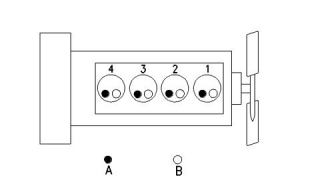
The No. 1 cylinder is the front cylinder.
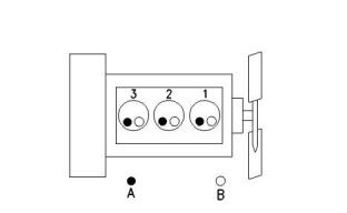
403F-15T Engine
Illustration 22
g00296424
(A) Exhaust valves
(B) Inlet valves
Table 2
404F-22 Engine Specifications
Maximum Operating Speed
(rpm)
3000 rpm
Cylinders and Arrangement
Bore
In-Line 4 cylinder
84.0 mm (3.31 inch)
100.0 mm (3.94 inch)
Illustration 21
g00852304
(A) Exhaust valves
(B) Inlet valves
Stroke
Displacement
Aspiration
2.216 L (135.229 in
3
)
NA(1)
Table 1
403F-15T Engine Specifications
Compression Ratio
Firing Order
23.3:1
Maximum Operating Speed
(rpm)
2800 rpm
In-Line 3 cylinder
1-3-4-2
Cylinders and Arrangement
(continued)
(continued)
This document is printed from SPI². Not for RESALE


![]()
![]()
![]()
![]()
![]()
24
SEBU8609
General Information
Product Description
(Table 2, contd)
Electronic Engine Features
Rotation that is viewed from the
flywheel
The engine operating conditions are monitored. The
Electronic Control Module (ECM) controls the
response of the engine to these conditions and to the
demands of the operator. These conditions and
operator demands determine the precise control of
fuel injection by the ECM. The electronic engine
control system provides the following features:
Counterclockwise
Valve Lash Setting (Inlet)
Valve Lash Setting (Exhaust)
Injection
0.20 mm (0.008 inch)
0.20 mm (0.008 inch)
Indirect
(1)
Naturally Aspirated
• Engine monitoring
404F-22T Engine
• Engine speed governing
• System diagnostics
• AftertreatmentRegeneration
• NOx reduction system control on the 404F-22T
engine
For more information on electronic engine features,
refer to the Operation and Maintenance Manual,
“Features and Controls” topic (Operation Section).
Engine Diagnostics
The engine has built-in diagnostics in order to ensure
that the engine systems are functioning correctly. The
operator will be alerted to the condition by a “Stop or
Warning” lamp. Under certain conditions, the engine
horsepower and the vehicle speed may be limited.
The electronic service tool may be used to display the
diagnostic codes.
Illustration 23
g00296424
(A) Exhaust valves
(B) Inlet valves
Table 3
There are four types of diagnostic codes: active code,
logged code, active event and logged event.
404F-22T Engine Specifications
Maximum Operating Speed
(rpm)
Most of the diagnostic codes are logged and stored in
the ECM. For additional information, refer to the
Operation and Maintenance Manual, “Engine
Diagnostics” topic (Operation Section).
3000 rpm
Cylinders and Arrangement
Bore
In-Line 4 cylinder
84.0 mm (3.31 inch)
100.0 mm (3.94 inch)
The ECM provides an electronic governor that
controls the injector output in order to maintain the
desired engine rpm.
Stroke
Displacement
Aspiration
2.216 L (135.229 in
3
)
T(1)
Engine Service Life
Compression Ratio
Firing Order
23.5:1
Engine efficiency and maximum utilization of engine
performance depend on the adherence to proper
operation and maintenance recommendations. In
addition, use recommended fuels, coolants, and
lubricants. Use the Operation and Maintenance
Manual as a guide for required engine maintenance.
1-3-4-2
Rotation that is viewed from the
flywheel
Counterclockwise
Valve Lash Setting (Inlet)
Valve Lash Setting (Exhaust)
Injection
0.20 mm (0.008 inch)
0.20 mm (0.008 inch)
Indirect
Expected engine life is generally predicted by the
average power that is demanded. The average power
that is demanded is based on fuel consumption of the
engine over a period of time. Reduced hours of
operation at full throttle and/or operating at reduced
throttle settings result in a lower average power
demand. Reduced hours of operation will increase
the length of operating time before an engine
overhaul is required.
(1)
Turbocharged
This document is printed from SPI². Not for RESALE


![]()

![]()
![]()
SEBU8609
25
General Information
Product Description
Aftermarket Products and Perkins
Engines
Perkins does not warrant the quality or performance
of non-Perkins fluids and filters.
When auxiliary devices, accessories, or consumables
(filters, additives, catalysts,) which are made by other
manufacturers are used on Perkins products, the
Perkins warranty is not affected simply because of
such use.
However, failures that result from the installation
or use of other manufacturers devices,
accessories, or consumables are NOT Perkins
defects. Therefore, the defects are NOTcovered
under the Perkins warranty.
AftertreatmentSystem
The aftertreatment system is approved for use by
Perkins . In order to be emission-compliant only the
approved Perkins aftertreatmentsystem must be
used on a Perkins engine.
This document is printed from SPI². Not for RESALE
![]()
26
SEBU8609
Product Identification Information
Plate Locations and Film Locations
Product Identification
Information
An example of an engine number is
ER*****U000001V.
ER
P
Engine family
Type of engine
i05140083
Plate Locations and Film
Locations
*****
The list number of the engine
Country of manufacture
U
0
The first digit is a production code.
Engine Serial Number
00001
V
Year of Manufacture
Perkins dealers or Perkins distributors need all of
these numbers in order to determine the components
that were included with the engine. This information
permits accurate identification of replacement part
numbers.
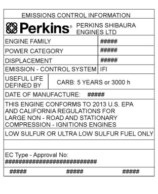
i05140229
Emissions CertificationFilm
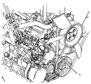
Illustration 24
g02335396
Typical example
(1) serial number plate
Perkins engines are identified by a serial number.
This number is shown on a serial number plate. The
serial number plate is mounted above the fuel
injection pump on the right-hand side of the engine
block.
Illustration 26
g02269574
Typical example
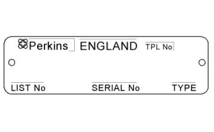
Illustration 25
g01094203
The emissions label, refer to illustration 26 is
installed on the front cover of the engine.
Typical example
This document is printed from SPI². Not for RESALE
![]()
![]()
![]()
![]()
![]()
![]()
![]()
![]()
![]()
![]()
![]()
![]()
![]()
![]()
SEBU8609
27
Product Identification Information
Reference Information
Identifying Numbers on Aftertreatment
Illustration 27
g02052934
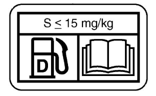
Perkins will supply the fuel label with every engine,
refer to illustration 27 . The equipment manufacturer
must install the label to the equipment. The label must
be attached to the equipment near the inlet of the fuel
tank. This action will comply with the EPA regulations.
The equipment manufacturer may install another fuel
label . If another fuel label is used, the equipment
manufacturer must send a drawing or a photo of the
label to Perkins. This action will ensure compliance of
the label.
i05157330
Reference Information
Information for the following items may be needed to
order parts. Locate the information for your engine.
Record the information in the appropriate space.
Make a copy of this list for a record. Keep the
information for future reference.
Record for Reference
Engine Model
Engine Serial number
Engine rpm
In-Line fuel filter
Fuel Filter Element
Lubrication Oil Filter
Crankcase Breather Element
Total Lubrication System Capacity
Total Cooling System Capacity
Air Cleaner Element
Fan Belt
Belt for Air Pump
This document is printed from SPI². Not for RESALE
![]()
![]()
![]()
![]()
![]()
![]()
![]()
![]()
![]()
![]()
![]()
![]()
![]()
![]()
![]()
![]()
28
SEBU8609
Operation Section
Product Lifting
Operation Section
Lifting and Storage
Lifting eyes are designed and installed for specific
engine arrangements. Alterations to the lifting eyes
and/or the engine make the lifting eyes and the lifting
fixtures obsolete. If alterations are made, ensure that
correct lifting devices are provided. Consult your
Perkins dealer or your Perkins distributor for
information regarding fixtures for correct engine
lifting.
i05140249
Product Lifting
Lifting Eyes with Top Mounted
Aftertreatment
Illustration 29
g03321882
i04053009
(1) Front lifting eye
(2) Rear lifting eye
Product Storage
(Engine and Aftertreatment)
Illustration 28
g03274116
Typical example
(1) Front lifting eye
(2) Rear lifting eyes
Perkins are not responsible for damage which may
occur when an engine is in storage after a period in
service.
Note: The engine assembly has three lifting eyes,
refer to illustration 28 .
Use a hoist to remove heavy components. Use an
adjustable lifting beam to lift the engine. All
supporting members (chains and cables) should be
parallel to each other. The chains and cables should
be perpendicular to the top of the object that is being
lifted.
Your Perkins dealer or your Perkins distributor can
assist in preparing the engine for extended storage
periods.
Condition for Storage
The engine must be stored in a water proof building.
The building must be kept at a constant temperature.
Engines that are filled with Perkins ELC will have
coolant protection to an ambient temperature of
−36° C (−32.8° F). The engine must not be subjected
to extreme variations in temperature and humidity.
To remove the engine ONLY, use the lifting eyes that
are on the engine.
This document is printed from SPI². Not for RESALE
![]()
![]()
![]()
![]()
![]()
SEBU8609
29
Lifting and Storage
Product Storage
Storage Period
Aftertreatment
No special procedures are required. The exhaust
outlet of the aftertreatment should be capped. Before
storing, the engine and the aftertreatment must be
enclosed in a cover.
An engine can be stored for up to 6 months provided
all the recommendation are adhered to.
Storage Procedure
Monthly Checks
Keep a record of the procedure that has been
completed on the engine.
The crankshaft must be rotated in order to change the
spring loading on the valve train. Rotate the
crankshaft more than 180 degrees. Visibly check for
damage or corrosion to the engine and
aftertreatment.
Note: Do not store an engine that has biodiesel in the
fuel system.
1. Ensure that the engine is clean and dry.
Ensure that the engine and aftertreatment are
covered completely before storage. Log the
procedure in the record for the engine.
a.
b.
If the engine has been operated using
biodiesel, the system must be drained and
new filters installed. The fuel tank will require
flushing.
Fill the fuel system with an ultra low sulfur fuel.
For more information on acceptable fuels refer
to this Operation and Maintenance Manual,
“Fluid recommendations”. Operate the engine
for 15 minutes in order to remove all biodiesel
from the system.
2. Drain any water from the primary filter water
separator. Ensure that the fuel tank is full.
3. The engine oil will not need to be drained in order
to store the engine. Provided the correct
specification of engine oil is used the engine can
be stored for up to 6 months. For the correct
specification of engine oil refer to this Operation
and Maintenance Manual, “Fluid
recommendations”.
4. Remove the drive belts from the engine.
Sealed Coolant System
Ensure that the cooling system is filled with Perkins
ELC, or an antifreeze that meets ASTM D6210
specification.
Open Cooling System
Ensure that all cooling drain plugs have been
opened. Allow the coolant to drain. Install the drain
plugs. Place a vapor phase inhibitor into the system.
The coolant system must be sealed once the vapor
phase inhibitor has been introduced. The effect of the
vapor phase inhibitor will be lost if the cooling system
is open to the atmosphere.
For maintenance procedures ref to this Operation and
Maintenance Manual.
This document is printed from SPI². Not for RESALE
![]()
30
SEBU8609
Features and Controls
Alarms and Shutoffs
Features and Controls
Coolant temperature – The coolant temperature
sensor indicates high jacket water coolant
temperature.
i05142391
Engine oil pressure – The engine oil pressure
sensor or switch, indicates when oil pressure drops
below rated system pressure, at a set engine speed.
Alarms and Shutoffs
Boost pressure (Intake manifold pressure – The
intake manifold pressure sensor checks the rated
pressure in the engine manifold.
• ECM
• DOC
• DPF
• ARD
Electronic Control Module
Diesel Oxidation Catalyst
Intake manifold air temperature – The intake
manifold air temperature sensor indicates high intake
air temperature.
Diesel Particulate Filter
Aftertreatment Regeneration Device
Atmospheric pressure – The atmospheric pressure
sensor checks the air pressure in the location that the
engine is operating.
Shutoffs
The shutoffs are electrically operated or mechanically
operated. The electrically operated shutoffs are
controlled by the ECM.
AftertreatmentAlarms
DOC inlet temperature – The inlet temperature
sensor checks the operating temperature.
Shutoffs are set at critical levels for the following
items:
DPF inlet temperature – The inlet temperature
sensor checks the operating temperature.
• Operating temperature
• Operating RPM
DPF outlet temperature – The outlet temperature
sensor checks the operating temperature.
• Overspeed
Delta P sensor (Differentialpressure) – The sensor
checks the differential pressure within the system.
• Aftertreatment regeneration
The particular shutoff may need to be reset before the
engine will start.
ARD temperature – The sensor checks the
temperature within the burner in the ARD system
NOTICE
Testing
Always determine the cause of the engine shutdown.
Make necessary repairs before attempting to restart
the engine.
Turning the keyswitch to the ON position will check
the indicator lights on the control panel. All the
indicator lights will be illuminated for 2 seconds after
the keyswitch is operated. Replace suspect bulbs
immediately.
Be familiar with the following items:
• Types and locations of shutoff
If any lamps stay illuminated or flashes, the fault must
be investigated immediately. The fault will create a
diagnostic code.
• Conditions which cause each shutoff to function
• The resetting procedure that is required to restart
the engine
Refer to Troubleshooting, “Diagnostic Trouble Code”
for more information.
Alarms
i05140291
The alarms are electrically operated. The operations
of the alarms are controlled by the ECM.
Gauges and Indicators
The alarm is operated by a sensor or by a switch.
When the sensor or the switch is activated, a signal is
sent to the ECM. An event code is created by the
ECM. The ECM will send a signal in order to
illuminate the lamp. Some application may have a
display panel in order to alert the operator.
Your engine may not have the same gauges or all of
the gauges that are described. For more information
about the gauge package, see the OEM information.
Your engine may be equipped with the following
sensors or switches:
This document is printed from SPI². Not for RESALE
![]()
![]()
![]()
![]()
![]()
![]()
![]()
SEBU8609
31
Features and Controls
Gauges and Indicators
Gauges provide indications of engine performance.
Ensure that the gauges are in good working order.
Determine the normal operating range by observing
the gauges over a period of time.
Tachometer – This gauge indicates
engine speed (rpm). When the throttle
control lever is moved to the full throttle
position without load, the engine is running at
high idle. The engine is running at the full load
rpm when the throttle control lever is at the full
throttle position with maximum rated load.
Noticeable changes in gauge readings indicate
potential gauge or engine problems. Problems may
also be indicated by gauge readings that change
even if the readings are within specifications.
Determine and correct the cause of any significant
change in the readings. Consult your Perkins dealer
or your Perkins distributor for assistance.
NOTICE
To help prevent engine damage, never exceed the
high idle rpm. Overspeeding can result in serious
damage to the engine. The engine can be operated at
high idle without damage, but should never be al-
lowed to exceed high idle rpm.
NOTICE
If no oil pressure is indicated, STOP the engine. If
maximum coolant temperature is exceeded, STOP
the engine. Engine damage can result.
Ammeter – This gauge indicates the
amount of charge or discharge in the
Engine Oil Pressure – The oil pressure
should be greatest after a cold engine is
started. The typical engine oil pressure
with SAE10W30 is 207 to 413 kPa (30 to 60 psi) at
rated rpm.
battery charging circuit. Operation of the
indicator should be to the right side of “0” (zero).
Fuel Level – This gauge indicates the
fuel level in the fuel tank. The fuel level
gauge operates when the “START/
A lower oil pressure is normal at low idle. If the load is
stable and the gauge reading changes, perform the
following procedure:
STOP” switch is in the “ON” position.
Service Hour Meter – The gauge
indicates operating time of the engine.
1. Remove the load.
Indicators and Lamps
• Shutdown lamp
2. Reduce engine speed to low idle.
3. Check and maintain the oil level.
• Warning lamp
Jacket Water Coolant Temperature –
Typical temperature range is 71 to 96°C
(160 to 205°F). The maximum allowable
temperature with the pressurized cooling system
at 90 kPa (13 psi) is 125° C (257° F). Higher
temperatures may occur under certain
conditions. The water temperature reading may
vary according to load. The reading should never
exceed the boiling point for the pressurized
system that is being used.
• Low-pressure oil lamp
For more information on indicator lamps refer to this
Operation and Maintenance Manual, “Monitoring
System (Table for Indicators Lamps)”. All lamps will
be illuminated for 2 seconds in order to check that the
lamps are functioning when the keyswitch is turned to
the ON position. Any lamp that fails to illuminate
during the first 2 second must be replaced. If any of
the lamps stay illuminated, the reason must be
investigated immediately.
If the engine is operating above the normal range and
steam becomes apparent, perform the following
procedure:
AftertreatmentLamps
There are three aftertreatment lamps.
• Regeneration Active Lamp
1. Reduce the load and the engine rpm.
2. Inspect the cooling system for leaks.
• Regeneration Disabled Lamp
• Diesel Particulate Filter (DPF) Lamp
3. Determine if the engine must be shut down
immediately or if the engine can be cooled by
reducing the load.
For information on the aftertreatmentlamps and
warning lamps refer to this Operation and
Maintenance Manual, “Diesel Particulate Filter
Regeneration”
This document is printed from SPI². Not for RESALE
![]()
![]()
![]()
![]()
![]()
![]()
![]()
![]()
![]()
![]()
![]()
32
SEBU8609
Features and Controls
Monitoring System
i05182480
“Warning”
Monitoring System
The orange “Warning” lamp will turn “ON” and the
warning signal is activated continuously in order to
alert the operator that one or more of the engine
parameters is not within normal operating range.
“Derate”
If the Shutdown mode has been selected and the
warning indicator activates, engine shutdown
may take as little as 20 seconds from the time the
warning indicator is activated. Depending on the
application, special precautions should be taken
to avoid personal injury. The engine can be re-
started following shutdown for emergency ma-
neuvers, if necessary.
The orange “Warning” lamp will be “Flashing” . After
the warning, the engine power will be derated. The
warning lamp will begin to flash when the derating
occurs.
The engine will be derated if the engine exceeds
preset operational limits. The engine derate is
achieved by restricting the amount of fuel that is
available for each injection. The amount of this
reduction of fuel is dependent on the severity of the
fault that has caused the engine derate, typically up
to a limit of 50%. This reduction in fuel results in a
predetermined reduction in engine power.
NOTICE
The Engine Monitoring System is not a guarantee
against catastrophic failures. Programmed delays
and derate schedules are designed to minimize false
alarms and provide time for the operator to stop the
engine.
“Shutdown”
The orange warning will be “Flashing” . After the
warning, the engine power will be derated. The
engine will continue at the rpm of the set derate until a
shutdown of the engine occurs. After shutdown the
red stop lamp will illuminate. The engine can be
restarted after a shutdown for use in an emergency.
The following parameters are monitored:
• Coolant temperature
• Intake manifold air pressure
• Oil pressure
A shutdown of the engine after been triggered is
immediate. The engine can be restarted after a
shutdown for use in an emergency. However, the
cause of the initial shutdown may still exist.
• Engine speed/timing
If there is a signal for high coolant temperature, there
will be a 2 second delay in order to verify the
condition.
• Atmospheric pressure (Barometric pressure) if
equipped
• The amount of soot in the Diesel particulate filter
If there is a signal for low oil pressure, there will be a
2 second delay in order to verify the condition.
•
Battery voltage
For information on the operation of the warning lamps
and the shutdown lamp, refer to this Operation and
Maintenance Manual, “Monitoring System (Table for
Indicator Lamps)”. For each of the programmed
modes, refer to Troubleshooting Guide, “Indicator
Lamps” for more information on Indicator Lamps.
Programmable Options and
Systems Operation
For more information or assistance for repairs,
consult your Perkins dealer or your Perkins
distributor.
If the Warning/Derate/Shutdown mode has been
selected and the warning indicator activates,
bring the engine to a stop whenever possible. De-
pending on the application, special precautions
should be taken to avoid personal injury.
The engine can be programmed to the following
modes:
This document is printed from SPI². Not for RESALE
![]()
![]()
![]()
![]()
![]()
![]()
![]()
SEBU8609
33
Features and Controls
Monitoring System
i05113371
Monitoring System
(Engine Warning Indicators)
Table 4
Table for Warning Indicators
Warning Indicator
Shutdown
Indicator
Indicator State
Description of the
Indication
Engine Status
Operator Action
ON
ON
Indicator Check
Keyswitch in the ON posi- Power ON, Indicator If any of the Indicators will
tion all Indicators should il- check
not illuminate during the
Indicator check, the fault
must be investigated
immediately.
luminate for 2 seconds.
Engine is not
The aftertreatment Indicatorswill also
be checked during Indicator check.
operating.
If any Indicator stay illumi-
nated or flash, the fault
must be investigated
immediately.
OFF
OFF
OFF
No Fault
Level 1
-
Engine operating
normally.
None
Level 1
ON (Solid)
An active diagnostic code The engine is operat- As soon as possible the
is present.
ing, but one or more
diagnostic codes are
present.
diagnostic code should be
investigated.
Level 2
Flashing
Flashing
OFF
ON
Level 2
Level 3
The ECM has detected an If enabled, the engine Stop the engine.
abnormal condition.
will be derated.
Investigate the fault.
Level 3
Engine condition is
abnormal.
The engine will auto- Stop engine immediately.
matically shut down. Investigate the fault.
If shut down is not en-
abled, the engine can
operate until damage
is coursed.
i05182498
i05142078
Overspeed
Sensors and Electrical
Components
(Engine and Aftertreatment)
• 403F-15T
• 404F-22
• 404F-22T
3000 RPM
3000 RPM
3000 RPM
• ARD
• DOC
• DPF
• ECM
• NRS
Aftertreatment Regeneration Devise
Diesel Oxidation Catalyst
Diesel Particulate Filter
The overspeed is plus 700 RPM above the given
speed for engines shown.
Electronic Control Module
NOx Reduction System
This document is printed from SPI². Not for RESALE

![]()
![]()
![]()
![]()
![]()
![]()
![]()
![]()
![]()
34
SEBU8609
Features and Controls
Sensors and Electrical Components
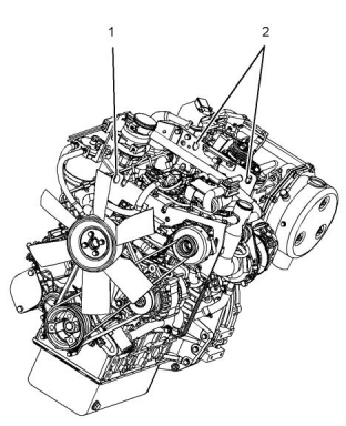
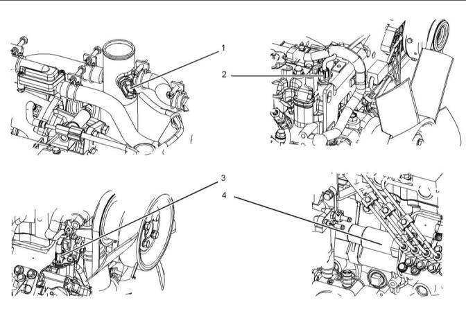
Illustration 30
g03276099
(1) Inlet air temperature sensor
(2) Oil pressure switch
(4) Fuel rack solenoid and position sensor
(5) Glow plugs
(7) Fuel pump/Primingpump
(3) Secondary speed sensor
(6) Resistor for ARD glow plug
This document is printed from SPI². Not for RESALE
![]()
![]()
SEBU8609
35
Features and Controls
Sensors and Electrical Components
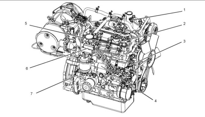
Illustration 31
g03276102
(8) Air pump
(9) Coolant temperature sensor
(10) Alternator
(11) Primary speed sensor
(12) Inlet manifold air pressure sensor
(13) NRS control valve
(14) Solenoid for starting motor
(15) Starting motor
This document is printed from SPI². Not for RESALE
![]()
![]()
36
SEBU8609
Features and Controls
Sensors and Electrical Components
Illustration 32
g03279116
(16) ARD glow plug
(17) DPF pressure differential sensor
(18) ARD injectors
(19) ARD temperature sensor
(20) DOC intake temperaturesensor
(21) DPF intake temperature sensor
(22) DPF outlet temperaturesensor
(23) ECM
The ECM is remotely mounted. The position of ECM
will depend upon the application.
This document is printed from SPI². Not for RESALE
![]()
![]()
SEBU8609
37
Features and Controls
Sensors and Electrical Components
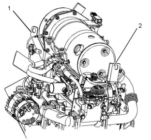
Illustration 33
g03279862
(1) Inlet air temperature
(2) Oil pressure switch
(3) Secondary speed sensor
(4) Fuel rack solenoid and position sensor
This document is printed from SPI². Not for RESALE
![]()
![]()
38
SEBU8609
Features and Controls
Sensors and Electrical Components
Illustration 34
g03280057
(5) Glow plugs
(6) Resistor for ARD glow plug
(7) Fuel pump/Primingpump
This document is printed from SPI². Not for RESALE
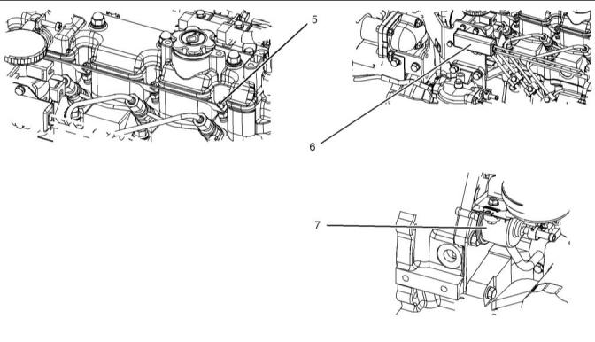
![]()
![]()
SEBU8609
39
Features and Controls
Sensors and Electrical Components
Illustration 35
g03299376
(8) Air pump
(10) Alternator
(9) Coolant temperature sensor
(11) Primary speed sensor
This document is printed from SPI². Not for RESALE
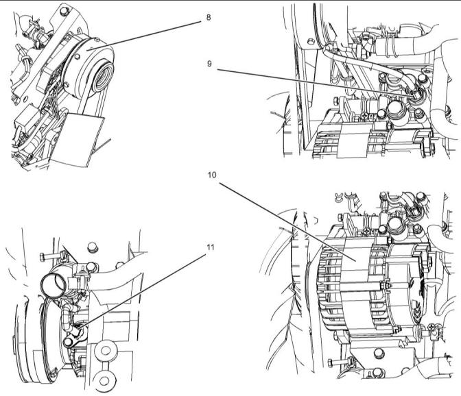
![]()
![]()
,
40
SEBU8609
Features and Controls
Sensors and Electrical Components
Illustration 36
g03299456
(12) Inlet manifold air pressure sensor
(13) NRS control valve
(14) Solenoid for starting motor
(15) Starting motor
(16) ARD glow plug
This document is printed from SPI². Not for RESALE
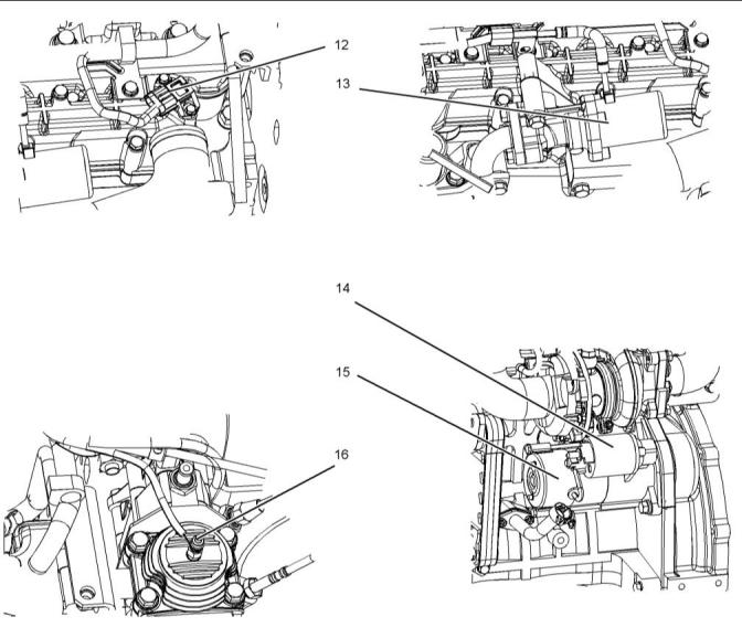
![]()
![]()
SEBU8609
41
Features and Controls
Sensors and Electrical Components
Illustration 37
g03299640
(17) DPF pressure differential sensor
(18) ARD injector 1
(18 A) ARD injector 2
(19) ARD temperature sensor
(19 A) Alterative position for the ARD
temperature sensor
This document is printed from SPI². Not for RESALE
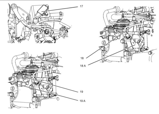
![]()
![]()
42
SEBU8609
Features and Controls
Sensors and Electrical Components
Illustration 38
g03299676
(20) DOC intake temperature sensor
(21) DPF intake temperaturesensor
(22) DPF outlet temperature sensor
(23) ECM
This document is printed from SPI². Not for RESALE
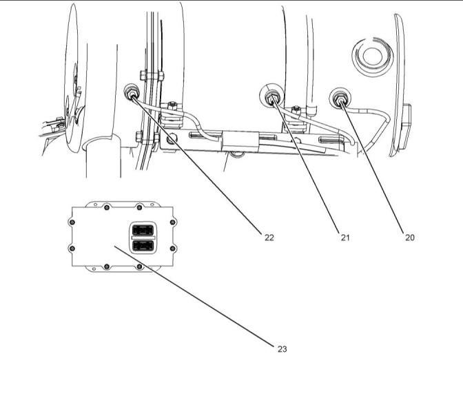
![]()
![]()
SEBU8609
43
Engine Diagnostics
Self-Diagnostics
Engine Diagnostics
i05142509
Fault Logging
i04053178
Self-Diagnostics
The system provides the capability of Fault Logging.
When the Electronic Control Module (ECM)
generates an active diagnostic code, the code will be
logged in the memory of the ECM. The codes that
have been logged by the ECM can be identified by
the electronic service tool. The active codes that have
been logged will be cleared when the fault has been
rectified or the fault is no longer active.
Perkins electronic engines have the capability to
perform a self-diagnostics test. When the system
detects an active problem, a diagnostic lamp is
activated. Diagnostic codes will be stored in
permanent memory in the Electronic Control Module
(ECM). The diagnostic codes can be retrieved by
using the electronic service tool. Refer to
Troubleshooting, “Electronic Service Tools” for further
information.
i05182507
Engine Operation with Active
Diagnostic Codes
Some installations have electronic displays that
provide direct readouts of the engine diagnostic
codes. Refer to the manual that is provided by the
OEM for more information on retrieving engine
diagnostic codes. Alternatively refer to
Troubleshooting, “Indicator Lamps” for further
information.
If a diagnostic lamp illuminates during normal engine
operation, the system has identified a situation that is
not within the specification. Use electronic service
tools to check the active diagnostic codes.
Active codes represent problems that currently exist.
These problems should be investigated first.
Note: The power will be limited until the problem is
corrected. If the oil pressure is within the normal
range, the engine may be operated at the rated
speed and load. However, maintenance should be
performed as soon as possible.
Logged codes represent the following items:
• Intermittent problems
• Recorded events
The active diagnostic code should be investigated.
The cause of the problem should be corrected as
soon as possible. If the cause of the active diagnostic
code is repaired and there is only one active
• Performance history
The problems may have been repaired since the
logging of the code. These codes do not indicate that
a repair is needed. The codes are guides or signals
when a situation exists. Codes may be helpful to
troubleshoot problems.
diagnostic code, the diagnostic lamp will turn off.
Operation of the engine and performance of the
engine can be limited as a result of the active
diagnostic code that is generated. Acceleration rates
may be significantly slower . Refer to the
Troubleshooting Guide for more information on the
relationship between these active diagnostic codes
and engine performance.
When the problems have been corrected, the
corresponding logged fault codes should be cleared.
i04053182
Diagnostic Lamp
i04053849
Engine Operation with
A diagnostic lamp is used to indicate the existence of
an active fault. Refer to Troubleshooting, “Indicator
Lamps” for more information. A fault diagnostic code
will remain active until the problem is repaired. The
diagnostic code may be retrieved by using the
electronic service tool. Refer to Troubleshooting,
“Electronic Service Tools” for more information.
IntermittentDiagnostic Codes
If a diagnostic lamp illuminates during normal engine
operation and the diagnostic lamp shuts off, an
intermittent fault may have occurred. If a fault has
occurred, the fault will be logged into the memory of
the Electronic Control Module (ECM).
This document is printed from SPI². Not for RESALE
![]()
44
SEBU8609
Engine Diagnostics
Configuration Parameters
In most cases, stopping the engine will not be
necessary because of an intermittent code. However,
the operator should retrieve the logged fault codes
and the operator should reference the appropriate
information. in order to identify the nature of the
event. The operator should log any observation that
could have caused the lamp to light.
• Low power
• Limits of the engine speed
• Engine vibration or engine noise
This information can be useful to help troubleshoot
the situation. The information can also be used for
future reference. For more information on diagnostic
codes, refer to the Troubleshooting Guide for this
engine.
i05142533
Configuration Parameters
System configuration parameters affect the emissions
of the engine or the power of the engine. System
configuration parameters are programmed at the
factory. Normally, system configuration parameters
would never change through the life of the engine.
System configuration parameters must be
reprogrammed if an Electronic Control Module (ECM)
is replaced. System configuration parameters are not
reprogrammed if the ECM software is changed.
For more information, refer to Troubleshooting,
“System Configuration Parameters”.
This document is printed from SPI². Not for RESALE
![]()
SEBU8609
45
Engine Starting
Before Starting Engine
Engine Starting
Do not use aerosol types of starting aids such as
ether. Such use could result in an explosion and
personal injury.
i04053911
Before Starting Engine
The ability to start the engine will be improved at
temperatures below −18 °C (0 °F) from the use of a
jacket water heater or extra battery capacity.
Perform the required daily maintenance and other
periodic maintenance before the engine is started.
Inspect the engine compartment. This inspection can
help prevent major repairs at a later date. Refer to the
Operation and Maintenance Manual, “Maintenance
Interval Schedule” for more information.
When Group 2 diesel fuel is used, the following items
provide a means of minimizing starting problems and
fuel problems in cold weather: Engine oil pan heaters,
jacket water heaters, fuel heaters and fuel line
insulation.
• Ensure that the engine has an adequate fuel
supply.
Use the procedure that follows for cold weather
starting.
• Open the fuel supply valve (if equipped).
Note: Do not adjust the engine speed control during
start-up. The electronic control module (ECM) will
control the engine speed during start-up.
If the engine has not been started for several weeks,
fuel may have drained from the fuel system. Air may
have entered the filter housing. Also, when fuel filters
have been changed, some air pockets will be trapped
in the engine. In these instances, prime the fuel
system. Refer to the Operation and Maintenance
Manual, “Fuel System - Prime” for more information
on priming the fuel system. Also, check that the fuel
specification is correct and that the fuel condition is
correct. Refer to the Operation and Maintenance
Manual, “Fuel Recommendations”.
1. Disengage any driven equipment.
Note: During key ON, the indicator lamps will be
illuminated for 2 seconds in order to check the lamp
operation. If any of the indicator lamps do not
illuminate check the bulb. If any indicator lamps stay
illuminated or flash, refer to Troubleshooting,
“Indicator Lamp Circuit - Test”.
2. Turn the keyswitch to the RUN position. Leave the
keyswitch in the RUN position until the warning
light for the glow plugs is extinguished.
Engine exhaust contains products of combustion
which may be harmful to your health. Always start
and operate the engine in a well ventilated area
and, if in an enclosed area, vent the exhaust to the
outside.
3. When the warning light for the glow plugs is
extinguished, turn the keyswitch to the START
position in order to engage the electric starting
motor and crank the engine.
• Do not start the engine or move any of the controls
if there is a “DO NOT OPERATE” warning tag or
similar warning tag attached to the start switch or
to the controls.
Note: The operating period of the warning light for the
glow plugs will change due to the ambient air
temperature.
• Reset all of the shutoffs or alarm components.
NOTICE
Do not engage the starting motor when flywheel is
turning. Do not start the engine under load.
• Ensure that any driven equipment has been
disengaged. Minimize electrical loads or remove
any electrical loads.
If the engine fails to start within 30 seconds, release
the starter switch or button and wait two minutes to al-
low the starting motor to cool before attempting to
start the engine again.
i05144913
Cold Weather Starting
4. Allow the keyswitch to return to the RUN position
after the engine starts.
S/N: EL11–Up
S/N: EN11–Up
5. Repeat step 2 through step 4 if the engine fails to
start.
This document is printed from SPI². Not for RESALE
![]()
![]()
![]()
![]()
![]()
![]()
![]()
46
SEBU8609
Engine Starting
Starting the Engine
Note: The engine should not be “raced” in order to
speed up the warm-up process.
NOTICE
Do not engage the starting motor when flywheel is
turning. Do not start the engine under load.
6. Allow the engine to idle for 3 to 5 minutes, or allow
the engine to idle until the water temperature
indicator begins to rise. When idling after the
engine has started in cold weather, increase the
engine rpm from 1000 to 1200 rpm. This operation
will warm up the engine more quickly. Maintaining
an elevated low idle speed for extended periods
will be easier with the installation of a hand throttle.
Allow the white smoke to disperse before
If the engine fails to start within 30 seconds, release
the starter switch or button and wait two minutes to al-
low the starting motor to cool before attempting to
start the engine again.
4. Allow the keyswitch to return to the RUN position
after the engine starts.
proceeding with normal operation.
5. Repeat step 2 through step 4 if the engine fails to
7. Operate the engine at low load until all systems
reach operating temperature. Check the gauges
during the warm-up period.
start.
i03663103
Starting with Jump Start
Cables
i05142649
Starting the Engine
Improper jump start cable connections can cause
an explosion resulting in personal injury.
Do not use aerosol types of starting aids such as
ether. Such use could result in an explosion and
personal injury.
Prevent sparks near the batteries. Sparks could
cause vapors to explode. Do not allow jump start
cable ends to contact each other or the engine.
Note: Do not adjust the engine speed control during
start-up. The electronic control module (ECM) will
control the engine speed during start-up.
Note: If it is possible, first diagnose the reason for the
starting failure. Refer to Troubleshooting, “Engine Will
Not Crank and Engine Cranks But Will Not Start” for
further information. Make any necessary repairs. If
the engine will not start only due to the condition of
the battery, either charge the battery, or start the
engine by using another battery with jump start
cables.
Starting the Engine
1. Disengage any equipment that is driven by the
engine.
Note: During key ON, the indicator lamps will be
illuminated for 2 seconds in order to check the lamp
operation. If any of the indicator lamps do not
illuminate check the bulb. If any indicator lamps stay
illuminated or flash, refer to Troubleshooting,
“Indicator Lamp Circuit - Test”.
2. Turn the keyswitch to the RUN position. Leave the
keyswitch in the RUN position until the warning
light for the glow plugs is extinguished.
The condition of the battery can be rechecked after
the engine has been switched OFF.
NOTICE
Using a battery source with the same voltage as the
electric starting motor. Use ONLY equal voltage for
jump starting. The use of higher voltage will damage
the electrical system.
Do not reverse the battery cables. The alternator can
be damaged. Attach ground cable last and remove
first.
3. When the warning light for the glow plugs has been
extinguished turn the keyswitch to the START
position. The starter motor will then crank the
engine.
Turn all electrical accessories OFF before attaching
the jump start cables.
Ensure that the main power switch is in the OFF posi-
tion before attaching the jump start cables to the en-
gine being started.
Note: The operating period of the warning light for the
glow plugs will change due to the ambient air
temperature.
This document is printed from SPI². Not for RESALE
![]()
![]()
![]()
![]()
![]()
![]()
![]()
![]()
![]()
SEBU8609
47
Engine Starting
After Starting Engine
1. Turn the start switch on the stalled engine to the
OFF position. Turn off all the engine's accessories.
Note: Gauge readings should be observed and the
data should be recorded frequently while the engine
is operating. Comparing the data over time will help to
determine normal readings for each gauge.
Comparing data over time will also help detect
abnormal operating developments. Significant
changes in the readings should be investigated.
2. Connect one positive end of the jump start cable to
the positive cable terminal of the discharged
battery. Connect the other positive end of the jump
start cable to the positive cable terminal of the
electrical source.
3. Connect one negative end of the jump start cable
to the negative cable terminal of the electrical
source. Connect the other negative end of the
jump start cable to the engine block or to the
chassis ground. This procedure helps to prevent
potential sparks from igniting the combustible
gases that are produced by some batteries.
Note: The engine ECM must be powered before the
starting motor is operated or damage can occur.
4. Start the engine in the normal operating procedure.
Refer to this Operation and Maintenance Manual,
“Starting the Engine”.
5. Immediately after the engine is started, disconnect
the jump start cables in reverse order.
After jump starting, the alternator may not be able to
fully recharge batteries that are severely discharged.
The batteries must be replaced or charged to the
proper voltage with a battery charger after the engine
is stopped. Many batteries which are considered
unusable are still rechargeable. Refer to Operation
and Maintenance Manual, “Battery - Replace” and
Testing and Adjusting Manual, “Battery - Test”.
i01903609
After Starting Engine
Note: In temperatures from 0 to 60°C (32 to 140°F),
the warm-up time is approximately three minutes. In
temperatures below 0°C (32°F), additional warm-up
time may be required.
When the engine idles during warm-up, observe the
following conditions:
• Check for any fluid or for any air leaks at idle rpm
and at one-half full rpm (no load on the engine)
before operating the engine under load. This is not
possible in some applications.
• Operate the engine at low idle until all systems
achieve operating temperatures. Check all gauges
during the warm-up period.
This document is printed from SPI². Not for RESALE
![]()
48
SEBU8609
Engine Operation
Engine Operation
Engine Operation
The operator will receive information on the status of
the ARD from dash lamps and the driver will be able
to request a regeneration by using a switch. Refer to
this Operation and Maintenance Manual, “Monitoring
System” for more information.
i05182510
Engine Operation
Engine Operation and Active
Regeneration
Proper operation and maintenance are key factors in
obtaining the maximum life and economy of the
engine. If the directions in the Operation and
Active regeneration can be performed at any engine
speed.
Maintenance Manual are followed, costs can be
minimized and engine service life can be maximized.
i05145051
The time that is needed for the engine to reach
normal operating temperature can be less than the
time taken for a walk-around inspection of the engine.
Diesel Particulate Filter
Regeneration
The engine can be operated at the rated rpm after the
engine is started and after the engine reaches
operating temperature. The engine will reach normal
operating temperature sooner during a low engine
speed (rpm) and during a low-power demand. This
procedure is more effective than idling the engine at
no load. The engine should reach operating
temperature in a few minutes.
Regeneration
Regeneration is the removal of soot from the Diesel
Particulate Filter (DPF). The Aftertreatment
Regeneration Device (ARD) is used to regenerate the
DPF. The DPF traps both soot and ash. The ash is
removed through a manual cleaning process. Refer
to Operation and Maintenance Manual, “Diesel
Particulate Filter - Clean” for more information on the
service of the DPF.
Avoid excess idling. Excessive idling causes carbon
buildup, engine slobber and soot loading of the
Diesel Particulate Filter (DPF). This excess idling is
harmful to the engine.
Gauge readings should be observed and the data
should be recorded frequently while the engine is
operating. Comparing the data over time will help to
determine normal readings for each gauge.
Comparing data over time will also help detect
abnormal operating developments. Significant
changes in the readings should be investigated.
Types of Regeneration
Passive Regeneration – The engine conditions are
sufficient for regeneration. The rate of regeneration is
much lower than active regeneration.
Active Regeneration – The engine duty cycle
conditions are not sufficient for passive regeneration
to occur.
Reduction of Particulate Emissions
The Diesel Particulate Filter (DPF) and the
AftertreatmentRegeneration Device (ARD) work
together in order to reduce particulate emissions. The
DPF collects the soot and any ash that is produced
by the combustion in the engine. During regeneration,
the soot is converted into a gas which is released into
the atmosphere. The Ash remains in the DPF until the
ash is cleaned out of the DPF.
Regeneration Indicators
Five Indicators can be affected by the DPF
regeneration.
Note: Amber or yellow Warning Indicator can be use
as a diagnostic Indicator. For more information refer
to this Operation and Maintenance Manual,
“Diagnostic Lamp”.
The temperature of the DPF must be above a
particular value in order for regeneration to occur. The
exhaust gas provides heat for the regeneration
process. There are two types of regeneration:
Regeneration Active – The Indicator is
illuminated during active regeneration.
The Indicator will stay on until the
aftertreatmenthas cooled.
Passive Regeneration – The engine conditions are
sufficient for regeneration. The rate of regeneration is
much lower than active regeneration.
DPF – This Indicator provides a general
indication of the soot load. The Indicator
is off when the soot load is normal.
Active Regeneration – The engine duty cycle
conditions are not sufficient for passive regeneration
to occur.
Note: If the Indicator is illuminated, a regeneration will
be required.
This document is printed from SPI². Not for RESALE
![]()
![]()
![]()
SEBU8609
49
Engine Operation
Diesel Particulate Filter Regeneration
Regeneration Disable – This Indicator is
illuminated whenever the disable switch
is activated or the system has been
• Refer to OEM for the applications interlocks
required to be engaged before regeneration can
take place.
disabled by the engine ECM.
Forced regeneration – A forced regeneration is
initiated by pressing the regeneration switch.
Amber or yellow Warning – This
Indicator, indicates that the soot load
has increased. Regeneration is required.
Also, the DPF Indicator will be illuminated. A
flashing indicator will cause an engine derate.
Soot Level Monitoringand
Indicators
Red Stop – This Indicator, indicates that
the soot load is extremely high. The soot
load is at level 3. The DPF Indicator will
be illuminated and the amber warning indicator
will be flashing. The engine will be shut down.
Note: In operation an Indicator can have two states,
on solid and flashing. The sequence is to give a
visual indication of the importance of the warning.
Some application may also have an audible warning
installed.
Regeneration Switch
Ensure that the engine maintenance is carried out at
the correct intervals. A lack of maintenance can result
in illumination of the warning Indicators. For the
correct intervals of maintenance, refer to the
Operation and Maintenance Manual, “Maintenance
Interval Schedule”.
The regeneration switch has three position force
regeneration, automatic regeneration, and disable
regeneration.
Note: Some OEMs may have other means of
activating a forced regeneration such as touch screen
interface.
Note: The MIDDLE position of the regeneration
switch is the default position for automatic mode of
regeneration.
Force Regeneration – Press in the top of
the switch for 2 seconds in order to
begin regeneration. An indicator light on
the switch will become active showing that the
regeneration is active. The regeneration active
Indicator will become active showing that the
regeneration is active.
Disable Regeneration – Press in the
bottom of the switch for 2 seconds in
order to disable regeneration. An
indicator light on the switch will become active.
The disable indicator will illuminate.
Note: To re-enable the regeneration, cycle the engine
start switch key or press and hold down the force
regeneration switch for 2 seconds.
Modes of Regeneration
• Automatic
• Forced Regeneration
Automatic regeneration is controlled by the engine
ECM.
Automatic – Automatic regeneration allows for the
DPF regeneration to start automatically with up to 80
percent load on the engine. In order for an automatic
regeneration to occur, the following conditions must
be met:
This document is printed from SPI². Not for RESALE
![]()
![]()
![]()
![]()
![]()
![]()
50
SEBU8609
Engine Operation
Fuel Conservation Practices
Table 5
Indicator Operation
Aftertreatment
Indicator
Aftertreatment Indi- Warning Indicator Warning Indicator Description
cator State
State
Action Required
All indicators are checked at key on. Any indicator illuminate after 2 seconds must be investigated. Any indicator that has not illuminated must be
investigated.
OFF
OFF
OFF
OFF
Normal operation
None
During passive regeneration NO indicators will be illuminated.
Regeneration active
ON
OFF
OFF
The indicator shows that
elevated emission tem-
peratures are possible.
The indicator will stay illu-
minated during
None
regeneration.
Regeneration active
DPF
ON
ON
OFF
OFF
OFF
Active regeneration occurring
OFF
Level 1
OFF
DPF
DPF
ON
OFF
Indication of soot loading An active regeneration
required
Level 2
ON solid
Amber Indicator
Flashing
Soot loading has
increased
Perform a forced regenera-
tion, or a service regenera-
tion will be required.
Level 3
DPF
ON solid
Amber Indicator
Stop indicator
Flashing
The flashing warning indi- A forced regenerationis
cator will indicate that the required.
engine has continued to Hold the forced regenera-
On solid
be operated
tion switch for 10 seconds
The STOP warning indi- before a regeneration be-
cator will indicate that the gins. If Regeneration can-
engine will be derated
and will be shut down.
After 30 seconds the en-
gine will automatically
shut down. The engine
can be restarted but will
only run for 30 seconds
before shutting down
again.
not occur, contact your
Perkins dealer or distributor
i04018232
Fuel expands when the fuel is warmed up. The fuel
may overflow from the fuel tank. Inspect fuel lines for
leaks. Repair the fuel lines, as needed.
Fuel ConservationPractices
• Be aware of the properties of the different fuels.
Use only the recommended fuels. Refer to the
Operations and Maintenance Manual, “Fuel
Recommendations”for further information.
The efficiency of the engine can affect the fuel
economy. Perkins design and technology in
manufacturing provides maximum fuel efficiency in all
applications. Follow the recommended procedures in
order to attain optimum performance for the life of the
engine.
• Avoid unnecessary idling.
Shut off the engine rather than idle for long periods of
time.
• Avoid spilling fuel.
This document is printed from SPI². Not for RESALE

![]()
SEBU8609
51
Engine Operation
Fuel Conservation Practices
• Observe the service indicator frequently. Keep the
air cleaner elements clean.
• Ensure that the turbocharger is operating correctly.
For more information refer to this Operation and
Maintenance Manual, “Turbocharger - Inspect”
• Maintain a good electrical system.
One faulty battery cell will overwork the alternator.
This fault will consume excess power and excess
fuel.
• The belt should be in good condition. Refer to the
Systems Operation, Testing and Adjusting, “V-Belt
Test” for further information.
• Ensure that all of the connections of the hoses are
tight. The connections should not leak.
• Ensure that the driven equipment is in good
working order.
• Cold engines consume excess fuel. Utilize heat
from the jacket water system and the exhaust
system, when possible. Keep cooling system
components clean and keep cooling system
components in good repair. Never operate the
engine without water temperature regulators. All of
these items will help maintain operating
temperatures.
This document is printed from SPI². Not for RESALE
![]()
52
SEBU8609
Cold Weather Operation
Cold Weather Operation
Cold Weather Operation
Hints for Cold Weather Operation
• If the engine will start, operate the engine until a
minimum operating temperature of 80° C (176° F)
is achieved. Achieving operating temperature will
help prevent the intake valves and exhaust valves
from sticking.
i04321989
Cold Weather Operation
• The cooling system and the lubrication system for
the engine do not lose heat immediately upon
shutdown. This means that an engine can be shut
down for a period and the engine can still have the
ability to start readily.
Perkins Diesel Engines can operate effectively in
cold weather. During cold weather, the starting and
the operation of the diesel engine is dependent on the
following items:
• The type of fuel that is used
• The viscosity of the engine oil
• The operation of the glow plugs
• Optional Cold starting aid
• Install the correct specification of engine lubricant
before the beginning of cold weather.
• Check all rubber parts (hoses, fan drive belts,)
weekly.
• Check all electrical wiring and connections for any
fraying or damaged insulation.
• Battery condition
This section will cover the following information:
• Keep all batteries fully charged and warm.
• Fill the fuel tank at the end of each shift.
• Potential problems that are caused by cold-
weather operation
• Check the air cleaners and the air intake daily.
Check the air intake more often when you operate
in snow.
• Suggest steps which can be taken in order to
minimize starting problems and operating
problems when the ambient air temperature is
between 0° to−40 °C (32° to 40 °F).
• Ensure that the glow plugs are in working order.
Refer to Troubleshooting, “Glow Plug Starting Aid-
Test”.
The operation and maintenance of an engine in
freezing temperatures is complex . This complexity is
because of the following conditions:
• Weather conditions
• Engine applications
Personal injury or property damage can result
from alcohol or starting fluids.
Recommendations from your Perkins dealer or your
Perkins distributor are based on past proven
practices. The information that is contained in this
section provides guidelines for cold-weather
operation.
Alcohol or starting fluids are highly flammable
and toxic and if improperly stored could result in
injury or property damage.
Do not use aerosol types of starting aids such as
ether. Such use could result in an explosion and
personal injury.
• For jump starting with cables in cold weather, refer
to the Operation and Maintenance Manual,
“Starting with Jump Start Cables.” for instructions.
This document is printed from SPI². Not for RESALE
![]()
![]()
![]()
![]()
![]()
SEBU8609
53
Cold Weather Operation
Cold Weather Operation
Viscosity of the Engine Lubrication
Oil
When the engine is operated below normal operating
temperatures, fuel and oil are not completely burned
in the combustion chamber. This fuel and oil causes
soft carbon deposits to form on the valve stems.
Generally, the deposits do not cause problems and
the deposits are burned off during operation at normal
engine operating temperatures.
Correct engine oil viscosity is essential. Oil viscosity
affects the amount of torque that is needed to crank
the engine. Refer to this Operation and Maintenance
Manual, “Fluid Recommendations” for the
recommended viscosity of oil.
When starting and stopping an engine many times
without being operated in order to warm up
completely, the carbon deposits become thicker. This
starting and stopping can cause the following
problems:
Recommendationsfor the Coolant
Provide cooling system protection for the lowest
expected outside temperature. Refer to this
Operation and Maintenance Manual, “Fluid
Recommendations” for the recommended coolant
mixture.
• Free operation of the valves is prevented.
• Valves become stuck.
In cold weather, check the coolant often for the
correct glycol concentration in order to ensure
adequate freeze protection.
• Pushrods may become bent.
• Other damage to valve train components can
result.
Engine Block Heaters
For this reason, when the engine is started, the
engine must be operated until the coolant
temperature is 80° C (176° F) minimum. Carbon
deposits on the valve stems will be kept at a minimum
and the free operation of the valves and the valve
components will be maintained.
Engine block heaters (if equipped) heat the engine
jacket water that surrounds the combustion
chambers. This heat provides the following functions:
• Startability is improved.
• Warm up time is reduced.
The engine must be thoroughly warmed in order to
keep other engine parts in better condition. The
service life of the engine will be generally extended.
Lubrication will be improved. There will be less acid
and less sludge in the oil. This condition will provide
longer service life for the engine bearings, the piston
rings, and other parts. However, limit unnecessary
idle time to 10 minutes in order to reduce wear and
unnecessary fuel consumption.
An electric block heater can be activated once the
engine is stopped. A block heater can be 110 V dc or
240 V dc. The output can be 750/1000W. Consult
your Perkins dealer or your Perkins distributor for
more information.
Idling the Engine
When idling after the engine is started in cold
weather, increase the engine rpm from 1000 to 1200
rpm. This idling will warm up the engine more quickly.
Maintaining an elevated low idle speed for extended
periods will be easier with the installation of a hand
throttle. The engine should not be “raced” in order to
speed up the warm-up process.
The Water Temperature Regulator and
Insulated Heater Lines
The engine is equipped with a water temperature
regulator. When the engine coolant is below the
correct operating temperature, jacket water circulates
through the engine cylinder block and into the engine
cylinder head. The coolant then returns to the cylinder
block via an internal passage that bypasses the valve
of the coolant temperature regulator. This ensures
that coolant flows around the engine under cold
operating conditions. The water temperature
regulator begins to open when the engine jacket
water has reached the correct minimum operating
temperature. As the jacket water coolant temperature
rises above the minimum operating temperature, the
water temperature regulator opens further allowing
more coolant through the radiator to dissipate excess
heat.
While the engine is idling, the application of a light
load (parasitic load) will assist in achieving the
minimum operating temperature. The minimum
operating temperature is 80° C (176° F).
Recommendationsfor Coolant
Warm Up
Warm up an engine that has cooled below normal
operating temperatures due to inactivity. This warm
-up should be performed before the engine is
returned to full operation. During operation in very
cold temperature conditions, damage to engine valve
mechanisms can result from engine operation for
short intervals. This damage can happen if the engine
is started and the engine is stopped many times
without being operated in order to warm up
completely.
The progressive opening of the water temperature
regulator operates the progressive closing of the
bypass passage between the cylinder block and
head. This action ensures maximum coolant flow to
the radiator in order to achieve maximum heat
dissipation.
This document is printed from SPI². Not for RESALE
![]()
54
SEBU8609
Cold Weather Operation
Fuel and the Effect from Cold Weather
Note: Do not restrict the air flow. Restriction of the air
flow can damage the fuel system. Perkins
discourages the use of all air flow restriction devices
such as radiator shutters. Restriction of the air flow
can result in the following: high exhaust
Group 2 fuels are considered acceptable for issues of
warranty. This group of fuels may reduce the life of
the engine, the engine's maximum power, and the
engine's fuel efficiency.
When Group 2 diesel fuels are used the following
components provide a means of minimizing problems
in cold weather:
temperatures, power loss, excessive fan usage and
reduction in fuel economy.
A cab heater is beneficial in very cold weather. The
feed from the engine and the return lines from the cab
should be insulated in order to reduce heat loss to the
outside air.
• Glow plugs (if equipped)
• Engine coolant heaters, which may be an OEM
option
Recommendationfor Crankcase Breather
Protection
• Fuel heaters, which may be an OEM option
• Fuel line insulation, which may be an OEM option
Crankcase ventilation gases contain a large quantity
of water vapor. This water vapor can freeze in cold
ambient conditions and can plug or damage the
crankcase ventilation system. If the engine is
operated in temperatures below −25° C (−13° F),
measures must be taken to prevent freezing and
plugging of the breather system. Insulated hoses and
a heated canister assembly should be installed.
There are three major differences between Group 1
fuels and Group 2 fuels. Group 1 fuels have the
following different characteristics to Group 2 fuels.
• A lower cloud point
• A lower pour point
• A higher energy per unit volume of fuel
Consult with your Perkins dealer or your Perkins
distributer for the recommended breather
components for operation from −25° to -40°C
(−13° to -72.°F).
Note: Group 3 fuels reduce the life of the engine. The
use of Group 3 fuels is not covered by the Perkins
warranty.
i02322217
Group 3 fuels include Low Temperature Fuels and
Aviation Kerosene Fuels .
Fuel and the Effect from Cold
Weather
Special fuels include Biofuel .
The cloud point is a temperature that allows wax
crystals to form in the fuel. These crystals can cause
the fuel filters to plug.
Note: Only use grades of fuel that are recommended
by Perkins . Refer to this Operation and Maintenance
Manual, “Fluid Recommendations”.
The pour point is the temperature when diesel fuel will
thicken. The diesel fuel becomes more resistant to
flow through fuel lines, fuel filters,and fuel pumps.
The following fuels can be used in this series of
engine.
Be aware of these facts when diesel fuel is
purchased. Consider the average ambient air
temperature for the engine's application. Engines that
are fueled in one climate may not operate well if the
engines are moved to another climate. Problems can
result due to changes in temperature.
• Group 1
• Group 2
• Group 3
Before troubleshooting for low power or for poor
performance in the winter, check the fuel for waxing.
• Special Fuels
Low temperature fuels may be available for engine
operation at temperatures below 0 °C (32 °F). These
fuels limit the formation of wax in the fuel at low
temperatures.
Perkins prefer only Group 1 and Group 2 fuels for
use in this series of engines.
Group 1 fuels are the preferred Group of Fuels for
general use by Perkins . Group 1 fuels maximize
engine life and engine performance. Group 1 fuels
are usually less available than Group 2 fuels.
Frequently, Group 1 fuels are not available in colder
climates during the winter.
For more information on cold weather operation, refer
to the Operation and Maintenance Manual, “Cold
Weather Operation and Fuel Related Components in
Cold Weather”.
Note: Group 2 fuels must have a maximum wear scar
of 650 micrometers (HFRR to ISO 12156-1).
This document is printed from SPI². Not for RESALE
![]()
SEBU8609
55
Cold Weather Operation
Fuel Related Components in Cold Weather
i05200880
Fuel Related Components in
Cold Weather
Fuel Tanks
Condensation can form in partially filled fuel tanks.
Top off the fuel tanks after you operate the engine.
Fuel tanks should contain some provision for draining
water and sediment from the bottom of the tanks.
Some fuel tanks use supply pipes that al, low , water
and sediment to settle below the end of the fuel
supply pipe.
Some fuel tanks use supply lines that take fuel
directly from the bottom of the tank. If the engine is
equipped with this system, regular maintenance of
the fuel system filter is important.
Drain the water and sediment from any fuel storage
tank at the following intervals: weekly, oil changes
and refueling of the fuel tank. This procedure will help
prevent water and/or sediment from being pumped
from the fuel storage tank and into the engine fuel
tank.
Fuel Filters
The engine must have an in-line fuel filter installed
between the fuel tank and the electric operated fuel
lift pump. After you change the fuel filter, always
prime the fuel system in order to remove air bubbles
from the fuel system. Refer to the Operation and
Maintenance Manual in the Maintenance Section for
more information on priming the fuel system.
Fuel Heaters
Fuel heaters help to prevent fuel filters from plugging
in cold weather due to waxing.
For further information on fuel heaters, consult your
Perkins dealer or distributor.
This document is printed from SPI². Not for RESALE
![]()
56
SEBU8609
Engine Stopping
Stopping the Engine
Engine Stopping
i03756631
After Stopping Engine
i02334873
Stopping the Engine
Note: Before you check the engine oil, do not operate
the engine for at least 10 minutes in order to allow the
engine oil to return to the oil pan.
NOTICE
• Check the crankcase oil level. Maintain the oil level
between the “MIN” mark and the “MAX” mark on
the engine oil level gauge.
Stopping the engine immediately after it has been
working under load, can result in overheating and ac-
celerated wear of the engine components.
• If necessary, perform minor adjustments. Repair
any leaks and tighten any loose bolts.
Avoid accelerating the engine prior to shutting it
down.
• If the engine is equipped with a service hour meter,
note the reading. Perform the maintenance that is
in the Operation and Maintenance Manual,
“Maintenance Interval Schedule”.
Avoiding hot engine shutdowns will maximize turbo-
charger shaft and bearing life.
Note: Individual applications will have different
control systems. Ensure that the shutoff procedures
are understood. Use the following general guidelines
in order to stop the engine.
• Fill the fuel tank in order to help prevent
accumulation of moisture in the fuel. Do not overfill
the fuel tank.
1. Remove the load from the engine. Reduce the
engine speed (rpm) to low idle. Allow the engine to
idle for five minutes in order to cool the engine.
NOTICE
Only use antifreeze/coolant mixtures recommended
in the Refill Capacities and Recommendations topic
that is in this Operation and Maintenance Manual.
Failure to do so can cause engine damage.
2. Stop the engine after the cool down period
according to the shutoff system on the engine and
turn the ignition key switch to the OFF position. If
necessary, refer to the instructions that are
provided by the OEM.
• Allow the engine to cool. Check the coolant level.
• If freezing temperatures are expected, check the
coolant for correct antifreeze protection. The
cooling system must be protected against freezing
to the lowest expected outside temperature. Add
the correct coolant/water mixture, if necessary.
i01903586
Emergency Stopping
• Perform all required periodic maintenance on all
driven equipment. This maintenance is outlined in
the instructions from the OEM.
NOTICE
Emergency shutoff controls are for EMERGENCY
use ONLY. DO NOT use emergency shutoff devices
or controls for normal stopping procedure.
The OEM may have equipped the application with an
emergency stop button. For more information about
the emergency stop button, refer to the OEM
information.
Ensure that any components for the external system
that support the engine operation are secured after
the engine is stopped.
This document is printed from SPI². Not for RESALE
![]()
![]()
![]()
![]()
![]()
![]()
![]()
SEBU8609
57
Maintenance Section
Refill Capacities
Maintenance Section
Refill Capacities
(Table 7, contd)
(1)
More than one style of sump may be used on these engines.
Use these values to estimate the refill capacity. Use the engine
oil level gauge to fill the engine to the correct oil level. Record
the result in this table. These values are the approximate ca-
pacities for the Crankcase Oil Sump which includes the stand-
ard factory installed oil filters. Engines with auxiliary oil filters will
require additional oil. Refer to the OEM specifications for the ca-
pacity of the auxiliary oil filter.
i05145430
Refill Capacities
(2)
The Total Lubrication System includes the capacity for the
Crankcase Oil Sump plus the capacity of factory installed oil fil-
ters and other filters added to the lubrication system. Enter the
value for the capacity of the Total Lubrication System in this row.
LubricationSystem
Cooling System
The refill capacities for the engine crankcase reflect
the approximate capacity of the crankcase or sump
plus standard oil filters. Auxiliary oil filter systems will
require additional oil. Refer to the OEM specifications
for the capacity of the auxiliary oil filter. Refer to the
Operation and Maintenance Manual, “Maintenance
Section” for more information on Lubricant
Specifications.
To maintain the cooling system, the Total Cooling
System capacity must be known. The approximate
capacity is for the engine cooling system. External
System capacities will vary among applications. Refer
to the OEM specifications for the External System
capacity. This capacity information will be needed in
order to determine the amount of coolant that is
required for the Total Cooling System.
403F-15T Engine
403F-15T Engine
Table 6
Table 8
403F-15T Engine
Refill Capacities
403F-15T Engine
Refill Capacities
Compartment or System
Minimum
Maximum
Compartment or System
Liters
Quarts
4.5 L
(4.8 qt)
6 L
(6.3 qt)
Crankcase Oil Sump(1)
Engine Only
2.6
2.7
External System Per OEM(1)
Total Cooling System(2)
Total Lubrication System(2)
(1)
These values are the approximate capacities for the crankcase
oil sump which includes the standard factory installed oil filters.
Engines with auxiliary oil filters will require additional oil. Refer
to the OEM specifications for the capacity of the auxiliary oil
filter.
(1)
The External System includes a radiator or an expansion tank
with the following components: heat exchanger and piping. Re-
fer to the OEM specifications. Enter the value for the capacity of
the External System in this row.
(2)
The Total Lubrication System includes the capacity for the
Crankcase Oil Sump plus the capacity of factory installed oil fil-
ters and other filters added to the lubrication system. Enter the
value for the capacity of the Total Lubrication System in this row.
(2)
The Total Cooling System capacity includes the capacity of the
Engine plus the External System. Enter the value for the ca-
pacity of the Total Cooling System in this row.
404F-22 Engine
404F-22 and 404F-22T Engines
Table 9
Table 7
404F-22 Engine
Refill Capacities
404F-22 and 404F-22T Engines
Refill Capacities
Compartment or System
Liters
Quarts
Compartment or System
Minimum
Maximum
Engine Only
3.61
3.8
8.9 L
10.6 L
Crankcase Oil Sump(1)
(9.4 qt)
(11.2 qt)
External System Per OEM(1)
Total Cooling System(2)
Total Lubrication System(2)
(1)
The External System includes a radiator or an expansion tank
with the following components: heat exchanger and piping. Re-
fer to the OEM specifications. Enter the value for the capacity of
the External System in this row.
(continued)
(2)
The Total Cooling System capacity includes the capacity for the
Engine plus the External System. Enter the value for the ca-
pacity of the Total Cooling System in this row.
This document is printed from SPI². Not for RESALE


![]()
58
SEBU8609
Refill Capacities
Fluid Recommendations
404F-22T Engine
Many engine failures are related to the cooling
system. The following problems are related to cooling
system failures: Overheating, leakage of the water
pump and plugged radiators or heat exchangers.
Table 10
404F-22T Engine
Refill Capacities
These failures can be avoided with correct cooling
system maintenance. Cooling system maintenance is
as important as maintenance of the fuel system and
the lubrication system. Quality of the coolant is as
important as the quality of the fuel and the lubricating
oil.
Compartment or System
Liters
Quarts
Engine Only
3.91
4.13
External System Per OEM(1)
Total Cooling System(2)
Coolant is normally composed of three elements:
Water, additives and glycol.
(1)
The External System includes a radiator or an expansion tank
with the following components: heat exchanger and piping. Re-
fer to the OEM specifications. Enter the value for the capacity of
the External System in this row.
Water
(2)
The Total Cooling System capacity includes the capacity for the
Engine plus the External System. Enter the value for the ca-
pacity of the Total Cooling System in this row.
Water is used in the cooling system in order to
transfer heat.
Distilled water or deionized water is
i05191400
recommended for use in engine cooling systems.
Fluid Recommendations
DO NOT use the following types of water in cooling
systems: Hard water, softened water that has been
conditioned with salt and sea water.
If distilled water or deionized water is not available,
use water with the properties that are listed in Table
11 .
General Coolant Information
NOTICE
Table 11
Never add coolant to an overheated engine. Engine
damage could result. Allow the engine to cool first.
Acceptable Water
Property
Chloride (Cl)
Sulfate (SO4)
Maximum Limit
40 mg/L
NOTICE
If the engine is to be stored in, or shipped to an area
with below freezing temperatures, the cooling system
must be either protected to the lowest outside temper-
ature or drained completely to prevent damage.
100 mg/L
Total Hardness
Total Solids
Acidity
170 mg/L
340 mg/L
pH of 5.5 to 9.0
NOTICE
Frequently check the specific gravity of the coolant for
proper freeze protection or for anti-boil protection.
For a water analysis, consult one of the following
sources:
• Local water utility company
• Agricultural agent
Clean the cooling system for the following reasons:
• Contamination of the cooling system
• Overheating of the engine
• Independent laboratory
Additives
• Foaming of the coolant
Additives help to protect the metal surfaces of the
cooling system. A lack of coolant additives or
insufficient amounts of additives enable the following
conditions to occur:
NOTICE
Never operate an engine without water temperature
regulators in the cooling system. Water temperature
regulators help to maintain the engine coolant at the
proper operating temperature. Cooling system prob-
lems
can
develop
without
water
temperature
regulators.
This document is printed from SPI². Not for RESALE


![]()
![]()
![]()
![]()
![]()
![]()
![]()
![]()
![]()
SEBU8609
59
Refill Capacities
Fluid Recommendations
• Corrosion
NOTICE
Do not use propylene glycol in concentrations that ex-
ceed 50 percent glycol because of the reduced heat
transfer capability of propylene glycol. Use ethylene
glycol in conditions that require additional protection
against boiling or freezing.
• Formation of mineral deposits
• Rust
• Scale
• Foaming of the coolant
Table 13
Many additives are depleted during engine operation.
These additives must be replaced periodically.
Propylene Glycol
Concentration
Freeze Protection
Additives must be added at the correct concentration.
Over concentration of additives can cause the
inhibitors to drop out-of-solution.The deposits can
enable the following problems to occur:
50 Percent
−29 °C (−20 °F)
To check the concentration of glycol in the coolant,
measure the specific gravity of the coolant.
• Formation of gel compounds
Coolant Recommendations
• Reduction of heat transfer
• Leakage of the water pump seal
• Plugging of radiators, coolers, and small passages
• ELC
• SCA
• ASTM
Extended Life Coolant
Supplement Coolant Additive
American Society for Testing and
Glycol
Materials
Glycol in the coolant helps to provide protection
against the following conditions:
The following two coolants are used in Perkins
diesel engines:
• Boiling
Preferred – Perkins ELC
• Freezing
Acceptable – A commercial heavy-duty antifreeze
• Cavitation of the water pump
that meets ASTM D6210 specifications
For optimum performance, Perkins recommends a
1:1 mixture of a water/glycol solution.
NOTICE
The 400F industrial engines must be operated
with a 1:1 mixture of water and glycol. This con-
centration allows the NOx reduction system to op-
erate correctly at high ambient temperatures.
Note: Use a mixture that will provide protection
against the lowest ambient temperature.
Note: 100 percent pure glycol will freeze at a
temperature of −23 °C (−9 °F).
NOTICE
Most conventional antifreezes use ethylene glycol.
Propylene glycol may also be used. In a 1:1 mixture
with water, ethylene and propylene glycol provide
similar protection against freezing and boiling. Refer
to Table 12 and refer to table 13 .
Do not use a commercial coolant/antifreeze that only
meets the ASTM D3306 specification. This type of
coolant/antifreeze is made for light automotive
applications.
Table 12
Ethylene Glycol
Perkins recommends a 1:1 mixture of water and
glycol. This mixture of water and glycol will provide
optimum heavy-duty performance as an antifreeze.
This ratio may be increased to 1:2 water to glycol if
extra freezing protection is required.
Concentration
50 Percent
Freeze Protection
−36 °C (−33 °F)
60 Percent
−51 °C (−60 °F)
A mixture of SCA inhibitor and water is acceptable
but will not give the same level of corrosion, boiling
and, freezing protection as ELC. Perkins
recommends a 6 percent to 8 percent concentration
of SCA in those cooling systems. Distilled water or
deionized water is preferred. Water which has the
recommended properties may be used
This document is printed from SPI². Not for RESALE
免费热线
400-100-8969 15088860848
400-100-8969 15088860848
机组销售
0574-26871589 15267810868
0574-26871589 15267810868
配件销售
0574-26886646 15706865167
0574-26886646 15706865167
维修热线
0574-26871569 18658287286
0574-26871569 18658287286
手机端

微信公众号