 English
 Espaol
 Franais
 阿拉伯
阿拉伯 中文(简)
中文(简) Deutsch
 Italiano
 Português
 日本
日本 韩国
韩国 български
 hrvatski
 esky
esky Dansk
Dansk Nederlands
 suomi
suomi Ελληνικ
 印度
印度 norsk
norsk Polski
 Roman
Roman русский
 Svenska
 珀金斯Perkins1204E-1206E故障排除,珀金斯Perkins1204E-1206E故障排除技术支持中心,珀金斯Perkins1204E-1206E故障排除代理商,珀金斯Perkins1204E-1206E故障排除销售服务中心,珀金斯Perkins1204E-1206E故障排除价格规格资料查询,宁波日昕动力科技有限公司

珀金斯Perkins1204E-1206E故障排除(英文)
详细描述
Troubleshooting
1204E-E44TA, 1204E-E44TTA and
1206E-E66TA Industrial Engines
BK1 (Engine)
MK1 (Engine)
ML1 (Engine)
This document is printed from SPI². Not for RESALE
![]()
![]()
![]()
![]()
Important Safety Information
Most accidents tha t involve produc t op eration, ma intena nc e and repair are caus ed by failure to
ob serve basic safety rules or precautions . An accident can often be avoided by recog nizing pote ntially
ha za rdous situations before an accident oc curs . A person mus t be alert to pote ntial ha za rds. This
person should also ha ve the ne cessary training, skills and tools to perform the se func tions properly.
Improper operation, lubrication, maintenance or repair of this product can be dangerous and
could result in injury or death.
Do not operate or perform any lubrication, maintenance or repair on this product, until you have
read and understood the operation, lubrication, maintenance and repair information.
Sa fety precautions and warning s are provided in this ma nua l and on the produc t. If the se ha za rd
warning s are not he eded, bod ily injury or death could oc cur to you or to othe r persons .
The ha za rds are identified by the “Safety Alert Symb ol” and followed by a “Signa l Word” suc h as
“DANGER”, “WARNING” or “CAUTION”. The Sa fety Alert “WARNING” label is shown below.
The me aning of this safety alert symb ol is as follows:
Attention! Become Alert! Your Safety is Involved.
The me ssage tha t appears und er the warning explains the ha za rd and can be either written or
pictorially presente d.
Op erations tha t ma y caus e produc t dama ge are identified by “NOTICE” labels on the produc t and in
this pub lication.
Perkins cannot anticipate every possible circumstance that might involve a potential hazard. The
warnings in this publication and on the product are, therefore, not all inclusive. If a tool, procedure,
work method or operating technique that is not specifically recommended by Perkins is used,
you must satisfy yourself that it is safe for you and for others. You should also ensure that the
product will not be damaged or be made unsafe by the operation, lubrication, maintenance or
repair procedures that you choose.
The informa tion, specifications , and illustrations in this pub lication are on the basis of informa tion tha t
was available at the time tha t the pub lication was written. The specifications , torque s, pressure s,
me asure me nts , adjustme nts , illustrations , and othe r items can cha ng e at any time. These cha ng es can
affect the service tha t is given to the produc t. Ob tain the comp lete and mos t current informa tion before
you start any job. Pe rkins dealers or Pe rkins distributors ha ve the mos t current informa tion available.
When replacement parts are required for this
product Perkins recommends using Perkins
replacement parts.
Failure to heed this warning can lead to prema-
ture failures, product damage, personal injury or
death.
This document is printed from SPI². Not for RESALE
![]()
![]()
KENR9116-01
3
Table of Contents
Table of Contents
Engine Stalls at Low RPM .................................... 94
Engine Top Speed Is Not Obtained ...................... 96
Engine Vibration Is Excessive ............................ 101
Exhaust Has Excessive Black Smoke ................ 102
Exhaust Has Excessive White Smoke ................ 104
Fuel Consumption Is Excessive .......................... 106
Fuel Contains Water ........................................... 108
Fuel Rail Pressure Problem ................................ 109
Fuel Temperature Is High .................................... 117
Inlet Air Is Restricted ............................................ 119
Inlet Air Temperature Is High .............................. 120
Intake Manifold Air Pressure Is High .................. 121
Intake Manifold Air Pressure Is Low ................... 122
Intake Manifold Air Temperature Is High ............. 123
NRS Exhaust Gas Temperature Is High ............ 124
NRS Mass Flow Rate Problem ........................... 127
Oil Consumption Is Excessive ............................ 130
Oil Contains Coolant ........................................... 132
Oil Contains Fuel ................................................ 133
Oil Pressure Is Low ............................................. 134
Power Is Intermittently Low or Power Cutout Is
Troubleshooting Section
Electronic Troubleshooting
Welding Precaution ................................................. 5
System Overview .................................................... 5
Glossary ................................................................ 12
Electronic Service Tools ........................................ 16
Indicator Lamps .................................................... 18
Replacing the ECM ............................................... 21
Self-Diagnostics .................................................... 22
Sensors and Electrical Connectors ....................... 22
Engine Wiring Information .................................... 31
ECM Harness Connector Terminals ..................... 36
Programming Parameters
Programming Parameters ..................................... 37
Test ECM Mode .................................................... 37
Factory Passwords ............................................... 37
Flash Programming .............................................. 38
Injector Code - Calibrate ....................................... 39
Mode Switch Setup ............................................... 40
Throttle Setup ....................................................... 41
Multiposition Switch Setup .................................... 44
Intermittent ........................................................ 136
Valve Lash Is Excessive ..................................... 141
Troubleshooting with a Diagnostic Code
Diagnostic Trouble Codes ................................... 142
Diagnostic Code Cross Reference ..................... 147
No Diagnostic Codes Detected ........................... 151
Customer Specified Parameters
Customer Specified Parameters ........................... 45
Customer Specified Parameters Table ................. 51
Customer Specified Parameters Worksheet ......... 54
Troubleshooting with an Event Code
Event Codes ...................................................... 152
Diagnostic Functional Tests
System Configuration Parameters
System Configuration Parameters ........................ 58
5 Volt Sensor Supply Circuit - Test ..................... 154
Analog Throttle Position Sensor Circuit - Test .... 163
CAN Data Link Circuit - Test ............................... 168
Data Link Circuit - Test ........................................ 172
Diesel Particulate Filter Identification Signal -
Symptom Troubleshooting
Acceleration Is Poor or Throttle Response Is
Poor .................................................................... 60
Alternator Is Noisy ................................................ 66
Alternator Problem ................................................ 66
Battery Problem .................................................... 66
Coolant Contains Oil ............................................. 67
Coolant Level Is Low ............................................ 67
Coolant Temperature Is High ................................ 68
Crankcase Breather Ejects Oil .............................. 71
Crankcase Fumes Disposal Tube Has Oil
Draining ............................................................... 72
Cylinder Is Noisy ................................................... 73
Diesel Particulate Filter Collects Excessive Soot .. 74
Diesel Particulate Filter Temperature Is Low ........ 75
ECM Does Not Communicate with Other
Modules .............................................................. 76
ECM Will Not Accept Factory Passwords ............. 76
Electronic Service Tool Does Not Communicate .. 77
Engine Cranks but Does Not Start ........................ 78
Engine Does Not Crank ........................................ 84
Engine Has Early Wear ........................................ 85
Engine Has Mechanical Noise (Knock) ................ 85
Engine Misfires, Runs Rough or Is Unstable ........ 86
Engine Overspeeds .............................................. 91
Engine Shutdown Occurs Intermittently ............... 92
Engine Speed Does Not Change .......................... 93
Test ................................................................... 179
Digital Throttle Position Sensor Circuit - Test ..... 183
ECM Memory - Test ............................................ 192
Electrical Connectors - Inspect ........................... 193
Engine Pressure Sensor Open or Short Circuit -
Test ................................................................... 197
Engine Speed/Timing Sensor Circuit - Test ........ 204
Engine Temperature Sensor Open or Short Circuit -
Test ................................................................... 212
Engine Temperature Sensor Open or Short Circuit -
Test ................................................................... 217
Ether Starting Aid - Test ...................................... 224
Fuel Pump Relay Circuit - Test ........................... 228
Glow Plug Starting Aid - Test .............................. 236
Idle Validation Switch Circuit - Test ..................... 242
Ignition Keyswitch Circuit and Battery Supply Circuit -
Test ................................................................... 248
Indicator Lamp Circuit - Test ............................... 255
Injector Data Incorrect - Test ............................... 258
Injector Solenoid Circuit - Test ............................ 260
Mode Selection Circuit - Test .............................. 267
Motorized Valve - Test ........................................ 271
PTO Switch Circuit - Test .................................... 276
Sensor Calibration Required - Test ..................... 279
Solenoid Valve - Test .......................................... 282
This document is printed from SPI². Not for RESALE
![]()
4
KENR9116-01
Table of Contents
Soot Sensor - Test .............................................. 288
Throttle Switch Circuit - Test ............................... 291
Valve Position Sensor - Test ............................... 295
Water In Fuel Sensor - Test ................................ 301
Index Section
Index ................................................................... 306
This document is printed from SPI². Not for RESALE
![]()
KENR9116-01
5
Troubleshooting Section
Troubleshooting Section
Electronic Troubleshooting
i04029202
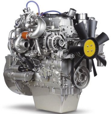
Welding Precaution
Correct welding procedures are necessary in order to
avoid damage to the following components:
• Electronic Control Module (ECM) on the engine
• Clean Emissions Module (CEM)
• Sensors
g01143634
Illustration 1
• Associated components
Service welding guide (typical diagram)
Components for the driven equipment should also be
considered. When possible, remove the component
that requires welding. When welding on an engine
that is equipped with an ECM and removal of the
component is not possible, the following procedure
must be followed. This procedure minimizes the risk
to the electronic components.
5. When possible, connect the ground clamp for
the welding equipment directly to the engine
component that will be welded. Place the clamp
as close as possible to the weld. Close positioning
reduces the risk of welding current damage to the
engine bearings, to the electrical components,
and to other components.
1. Stop the engine. Remove the electrical power
from the ECM.
6. Protect the wiring harnesses from welding debris
and/or from welding spatter.
2. Ensure that the fuel supply to the engine is turned
off.
7. Use standard welding procedures to weld the
materials together.
3. Disconnect the negative battery cable from the
battery. If a battery disconnect switch is installed,
open the switch.
i04155807
System Overview
4. Disconnect all electronic components from
the wiring harnesses. Include the following
components:
The engine has an electronic control system. The
system also monitors the Diesel Particulate Filter
(DPF) and the NOx Reduction System (NRS).
• Electronic components for the driven equipment
• ECM
The control system consists of the following
components:
• Sensors
• Electronically controlled valves
• Relays
• Electronic Control Module (ECM)
• Software (flash file)
• Wiring
• Aftertreatment ID module
NOTICE
• Sensors
Do not use electrical components (ECM or ECM sen-
sors) or electronic component grounding points for
grounding the welder.
• Actuators
This document is printed from SPI². Not for RESALE
![]()
![]()
![]()
![]()
6
KENR9116-01
Troubleshooting Section
The following information provides a general
description of the control system. Refer to Systems
Operation, Testing, and Adjusting for detailed
information about the control system.
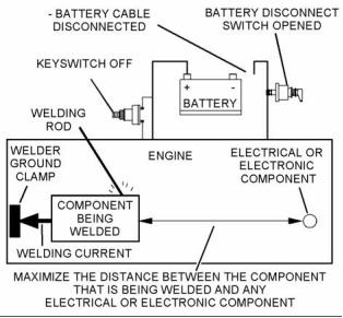
Electronic Control Circuit Diagram
g02476570
Illustration 2
Electronic control circuit diagram for the 1204E-E44 engine
This document is printed from SPI². Not for RESALE
![]()
![]()

KENR9116-01
7
Troubleshooting Section
g02476572
Illustration 3
Electronic control circuit diagram for the 1206E-E66 engine
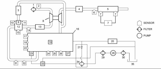
Block Diagram
Refer to Illustration 4 and Illustration 5 for block
diagrams of the control system.
This document is printed from SPI². Not for RESALE
![]()
![]()

8
KENR9116-01
Troubleshooting Section
g02477761
Illustration 4
Block diagram for the 1204E and 1206E engines with a single turbocharger
(1) Air cleaner
(13) Air-to-air aftercooler
(25) Oil pressure sensor
(2) Air inlet temperature sensor
(3) NRS cooler
(14) Wastegate regulator
(15) NRS outlet pressure sensor
(16) Engine
(17) Coolant temperature sensor
(18) Primary speed/timing sensor
(19) Fuel injectors
(26) Barometric pressure sensor
(27) ECM
(28) Electric fuel lift pump
(29) Primary fuel filter
(4) Exhaust back pressure valve
(5) Diesel Oxidation Catalyst (DOC) and
Diesel Particulate Filter (DPF)
(6) DPF inlet temperature sensor
(7) Soot sensor
(8) Turbocharger
(9) NRS valve
(10) NRS temperature sensor
(11) NRS inlet pressure sensor
(12) NRS mixer
(30) In-line fuel strainer
(31) Intake manifold pressure sensor
(32) Intake manifold air temperature sensor
(33) Transfer pump inlet regulator
(34) Secondary fuel filter
(35) Fuel tank
(20) Return fuel cooler
(21) Return fuel pressure relief valve
(22) Secondary speed/timing sensor
(23) High-pressure fuel pump/transfer
pump/fuel temperature sensor
(24) Fuel rail pressure sensor
This document is printed from SPI². Not for RESALE
![]()
![]()
KENR9116-01
9
Troubleshooting Section
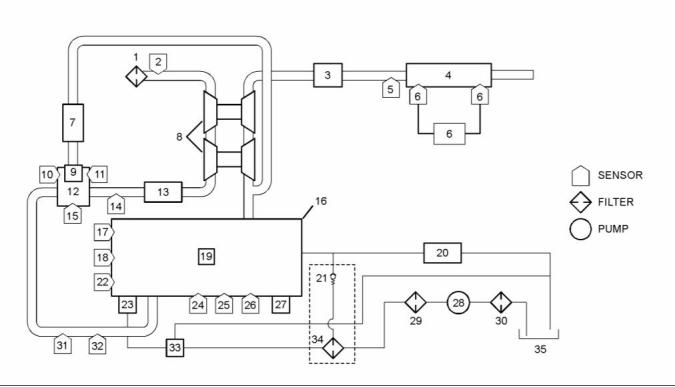
g02477778
Illustration 5
Block diagram for the 1204E-E44TTA engine with twin turbochargers
(1) Air cleaner
(13) Air-to-air aftercooler
(25) Oil pressure sensor
(2) Air inlet temperature sensor
(3) Exhaust back pressure valve
(4) Diesel Oxidation Catalyst (DOC) and
Diesel Particulate Filter (DPF)
(5) DPF inlet temperature sensor
(6) Soot sensor
(7) NRS cooler
(8) Turbochargers
(9) NRS valve
(14) Wastegate regulator
(15) NRS outlet pressure sensor
(16) Engine
(17) Coolant temperature sensor
(18) Primary speed/timing sensor
(19) Fuel injectors
(26) Barometric pressure sensor
(27) ECM
(28) Electric fuel lift pump
(29) Primary fuel filter
(30) In-line fuel strainer
(31) Intake manifold pressure sensor
(32) Intake manifold air temperature sensor
(33) Transfer pump inlet regulator
(34) Secondary fuel filter
(35) Fuel tank
(20) Return fuel cooler
(21) Return fuel pressure relief valve
(22) Secondary speed/timing sensor
(23) High-pressure fuel pump/transfer
pump/fuel temperature sensor
(24) Fuel rail pressure sensor
(10) NRS temperature sensor
(11) NRS inlet pressure sensor
(12) NRS mixer
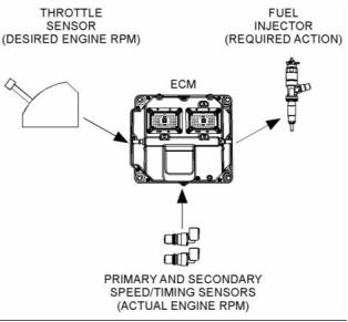
System Operation
Engine Governor
The ECM governs the engine. The ECM determines
the timing, the injection pressure, and the amount
of fuel that is delivered to each cylinder. These
factors are based on the actual conditions and on the
desired conditions at any given time during starting
and operation.
The governor uses the throttle position sensor to
determine the desired engine speed. The governor
compares the desired engine speed to the actual
engine speed. The actual engine speed is determined
through interpretation of the signals that are received
by the ECM from the engine speed/timing sensors. If
the desired engine speed is greater than the actual
engine speed, the governor injects more fuel in order
to increase engine speed.
This document is printed from SPI². Not for RESALE
![]()
![]()
10
KENR9116-01
Troubleshooting Section
Fuel Injection
The ECM sends a high voltage signal to the injector
solenoids in order to energize the solenoids. By
controlling the timing and the duration of the high
voltage signal, the ECM can control the following
aspects of injection:
• Injection timing
• Fuel delivery
The flash file inside the ECM establishes certain
limits on the amount of fuel that can be injected.
The FRC Fuel Limit is a limit that is based on the
intake manifold pressure. The FRC Fuel Limit is used
to control the air/fuel ratio for control of emissions.
When the ECM senses a higher intake manifold
pressure, the ECM increases the FRC Fuel Limit. A
higher intake manifold pressure indicates that there
is more air in the cylinder. When the ECM increases
the FRC Fuel Limit, the ECM allows more fuel into
the cylinder.
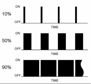
g01860934
Illustration 6
Typical example
The Rated Fuel Limit is a limit that is based on the
power rating of the engine and on the engine rpm.
The Rated Fuel Limit is like the rack stops and the
torque spring on a mechanically governed engine.
The Rated Fuel Limit provides the power curves
and the torque curves for a specific engine family
and a specific engine rating. All of these limits are
determined at the factory. These limits cannot be
changed.
The desired engine speed is typically determined by
one of the following conditions:
• The position of the throttle
• The desired engine speed in Power Take-Off (PTO)
Timing Considerations
Once the governor has determined the amount of
fuel that is required, the governor must determine
the timing of the fuel injection. Fuel injection timing is
determined by the ECM after considering input from
the following components:
Customer Parameters and Engine Speed
Governing
A unique feature with electronic engines is customer
specified parameters. These parameters allow the
owner of the machine to fine-tune the ECM for engine
operation. Fine-tuning the ECM allows the machine
owner to accommodate the typical usage of the
machine and the power train of the machine.
• Coolant temperature sensor
• Intake manifold air temperature sensor
• Intake manifold pressure sensor
• Barometric pressure sensor
Many of the customer parameters provide additional
restrictions on the actions that will be performed by
the ECM in response to input from the operator. The
PTO Top Engine Limit is an engine rpm limit that is
used by the ECM to limit the fuel during operation of
the PTO. The ECM will not fuel the injectors above
this rpm.
The ECM adjusts timing for optimum engine
performance and fuel economy. Actual timing and
desired timing cannot be viewed with the electronic
service tool. The ECM determines the location of
top center of the number one cylinder from the
signals that are provided by the engine speed/timing
sensors. The ECM determines when injection should
occur relative to top center position. The ECM then
provides the signal to the injector at the desired time.
Some parameters are intended to notify the operator
of potential engine damage (engine monitoring
parameters). Some parameters enhance fuel
economy (machine speed, engine speed limit,
and idle shutdown). Other parameters are used to
enhance the engine installation into the machine.
Other parameters are used to provide operating
information to the owner of the machine.
This document is printed from SPI². Not for RESALE
![]()
![]()
KENR9116-01
11
Troubleshooting Section
Other ECM Functions for
Performance
“Lifetime Total Engine Revolutions” is the total
number of revolutions that have been completed by
the engine crankshaft.
The ECM can also provide enhanced control of the
engine for machine functions such as controlling the
cooling fan. Refer to Troubleshooting, “Configuration
Parameters” for supplemental information about the
systems that can be monitored by the ECM in order
to provide enhanced machine performance, fuel
economy, and convenience for the operator.
“Average Load Factor” provides relative engine
operating information. “Average Load Factor”
compares actual operating information of the engine
to the maximum engine operation that is available.
“Average Load Factor” is determined by using “Total
Max Fuel”, “Total Idle Fuel”, and “Total Fuel”. All of
these parameters are available with the electronic
service tool. These parameters are available within
the menu for “Current Totals”.
ECM Lifetime Totals
The ECM maintains total data of the engine for the
following parameters:
Programmable Parameters
Certain parameters that affect engine operation
may be changed with the electronic service tool.
The parameters are stored in the ECM, and the
parameters are protected from unauthorized changes
by passwords. These parameters are either system
configuration parameters or customer parameters.
• “Total Operating Hours”
• “Engine Lifetime Hours”
• “Total Idle Time”
• “Total Idle Fuel”
System configuration parameters are set at the
factory. System configuration parameters affect
emissions or power ratings within an engine family.
Factory passwords must be obtained and factory
passwords must be used to change the system
configuration parameters.
• “Total Fuel”
• “Total Max Fuel”
• “Engine Starts”
Customer parameters are variable. Customer
parameters affect the following characteristics within
the limits that are set by the factory, by the monitoring
system, and by PTO operation:
• “Lifetime Total Engine Revolutions”
• “Average Load Factor”
The “Total Operating Hours” is the operating hours of
the engine. The operating hours do not include the
time when the ECM is powered but the engine is not
running.
• Rpm ratings
• Power ratings
Customer passwords may be required to change
customer specified parameters.
The “Engine Lifetime Hours” is the number of hours
when electrical power has been applied to the
engine. These hours will include the time when the
ECM is powered but the engine is not running.
Some of the parameters may affect engine operation
in an unusual way. An operator might not expect
this type of effect. Without adequate training,
these parameters may lead to power complaints
or performance complaints even though the
performance of the engine is to the specification.
“Total Idle Time” and “Total Idle Fuel” can include
operating time when the engine is not operating
under a load.
Fuel Information can be displayed in US gallons or
in liters.
Refer to Troubleshooting, “Configuration Parameters”
for additional information on this subject.
“Total Fuel” is the total amount of fuel that is
consumed by the engine during operation.
Passwords
“Total Max Fuel” is the maximum amount of fuel that
could have been consumed by the engine during
operation.
System configuration parameters are protected by
factory passwords. Factory passwords are calculated
on a computer system that is available only to
Perkins Distributors. Since factory passwords contain
alphabetic characters, only the electronic service
tool may change system configuration parameters.
System configuration parameters affect the power
rating family or emissions.
“Engine Starts” is the total number of times when the
engine has been started.
This document is printed from SPI². Not for RESALE
![]()
12
KENR9116-01
Troubleshooting Section
Customer parameters can be protected by
customer passwords. The customer passwords are
programmed by the customer. Factory passwords
can be used to change customer passwords if
customer passwords are lost.
Communication Adapter Tool – The
communication adapter provides a communication
link between the ECM and the electronic service tool.
Coolant Temperature Sensor – The coolant
temperature sensor detects the engine coolant
temperature for all normal operating conditions and
for engine monitoring.
Refer to Troubleshooting, “Factory Passwords” for
additional information on this subject.
Data Link – The data link is a serial communication
port that is used for communication with other devices
such as the electronic service tool.
i04156374
Glossary
Derate – Certain engine conditions will generate
event codes. Also, engine may be derated. The map
for the engine derate is programmed into the ECM
software. The type of derate can be one or more of
three types: reduction of rated power, reduction of
rated engine speed, and reduction of rated machine
speed for OEM products.
Active Diagnostic Code – An active diagnostic
code alerts the operator or the service technician that
an electronic system malfunction is currently present.
Refer to the term “Diagnostic Code” in this glossary.
Aftertreatment – Aftertreatment is a system that is
used to remove pollutants from exhaust gases. The
system consists of a Diesel Oxidation Catalyst (DOC)
and a Catalyzed Diesel Particulate Filter (CDPF).
Desired Engine Speed – The desired engine speed
is input to the electronic governor within the ECM.
The electronic governor uses the signal from the
throttle position sensor, the engine speed/timing
sensor, and other sensors in order to determine the
desired engine speed.
Alternating Current (AC) – Alternating current is an
electric current that reverses direction at a regular
interval that is reoccurring.
Diagnostic Trouble Code – A diagnostic trouble
code is sometimes referred to as a fault code. These
codes indicate an electronic system malfunction.
Before Top Center (BTC) – BTC is the 180 degrees
of crankshaft rotation before the piston reaches the
top center position in the normal direction of rotation.
Diagnostic Lamp – The diagnostic lamp is also
called the warning lamp. The diagnostic lamp is used
to warn the operator of the presence of an active
diagnostic code. The lamp may not be included in
all applications.
Breakout Harness – A breakout harness is a
test harness that is designed to connect into the
engine harness. This connection allows a normal
circuit operation and the connection simultaneously
provides a Breakout T in order to measure the
signals.
Diesel Oxidation Catalyst – The Diesel Oxidation
Catalyst is also known as the (DOC). The DOC is a
device in the exhaust system that oxidizes certain
elements in the exhaust gases. These elements can
include carbon monoxide (CO), hydrocarbons and
the soluble organic fractions (SOF) of particulate
matter.
Bypass Circuit – A bypass circuit is a circuit that is
used as a substitute circuit for an existing circuit. A
bypass circuit is typically used as a test circuit.
CAN Data Link (see also J1939 CAN Data Link) –
The CAN Data Link is a serial communications
port that is used for communication with other
microprocessor-based devices.
Digital Sensor Return – The common line (ground)
from the ECM is used as ground for the digital
sensors.
Catalyzed Diesel Particulate Filter – The Catalyzed
Diesel Particulate Filter (CDPF) filters particulates
from the exhaust gases. A coating on the internal
surfaces reacts with the hot exhaust gases in order
to burn off the particulates. This process prevents the
CDPF from becoming blocked with soot.
Digital Sensors – Digital sensors produce a pulse
width modulated signal. Digital sensors are supplied
with power from the ECM.
Digital Sensor Supply – The power supply for the
digital sensors is provided by the ECM.
Clean Emissions Module – The Clean Emissions
Module (CEM) includes all the components of the
aftertreatment system.
Direct Current (DC) – Direct current is the type of
current that flows consistently in only one direction.
DT, DT Connector, or Deutsch DT – This design is
a type of connector that is used on this engine. The
connectors are manufactured by Deutsch.
Code – Refer to “Diagnostic Trouble Code”.
This document is printed from SPI². Not for RESALE
![]()
KENR9116-01
13
Troubleshooting Section
Duty Cycle – Refer to “Pulse Width Modulation”.
Failure Mode Identifier (FMI) – This identifier
indicates the type of failure that is associated with
the component. The FMI has been adopted from the
SAE practice of J1587 diagnostics. The FMI follows
the parameter identifier (PID) in the descriptions of
the fault code. The descriptions of the FMIs are in
the following list.
Electronic Engine Control – The electronic
engine control is a complete electronic system.
The electronic engine control monitors the engine
operation under all conditions. The electronic engine
control also controls the engine operation under all
conditions.
0 – The data is valid but the data is above the normal
Electronic Control Module (ECM) – The ECM
is the control computer of the engine. The ECM
provides power to the electronics. The ECM monitors
data that is input from the sensors of the engine. The
ECM acts as a governor in order to control the speed
and the power of the engine.
operational range.
1 – The data is valid but the data is below the normal
operational range.
2 – The data is erratic, intermittent, or incorrect.
Electronic Service Tool – The electronic service
tool allows a computer (PC) to communicate with the
ECM.
3 – The voltage is above normal or the voltage is
shorted high.
4 – The voltage is below normal or the voltage is
shorted low.
Engine Monitoring – Engine Monitoring is the part
of the electronic engine control that monitors the
sensors. Engine monitoring also warns the operator
of detected problems.
5 – The current is below normal or the circuit is open.
6 – The current is above normal or the circuit is
grounded.
Engine Oil Pressure Sensor – The engine oil
pressure sensor measures engine oil pressure. The
sensor sends a signal to the ECM that is dependent
on the engine oil pressure.
7 – The mechanical system is not responding
properly.
Engine Speed/Timing Sensor – An engine
speed/timing sensor is a hall effect switch that
provides a digital signal to the ECM. The ECM
interprets this signal as the crankshaft position and
the engine speed. Two sensors are used to provide
the speed and timing signals to the ECM. The primary
sensor is associated with the crankshaft and the
secondary sensor is associated with the camshaft.
8 – There is an abnormal frequency, an abnormal
pulse width, or an abnormal time period.
9 – There has been an abnormal update.
10 – There is an abnormal rate of change.
11 – The failure mode is not identifiable.
12 – The device or the component is damaged.
13 – The device requires calibration.
Ether Injection – Ether injection is a starting aid in
cold conditions. Glow plugs are used as a starting
aid when the ambient temperature is between 5° C
(41° F) and −25° C (−13° F). At a temperature that
is lower than −25° C (−13° F), the glow plugs are
disabled and ether injection is used.
14 – There is a special instruction for the device.
15 – The signal from the device is high (least severe).
Event Code – An event code may be activated
in order to indicate an abnormal engine operating
condition. These codes usually indicate a mechanical
problem instead of an electrical system problem.
16 – The signal from the device is high (moderate
severity).
17 – The signal from the device is low (least severe).
Exhaust Back Pressure Valve – The exhaust back
pressure valve regulates the gas pressure in the
exhaust system. The valve can restrict the flow of
exhaust gases in order to increase the exhaust back
pressure. An increase in exhaust back pressure will
increase the temperature of the exhaust gases. The
increase in temperature will improve the process that
burns off the soot in the CDPF.
18 – The signal from the device is low (moderate
severity).
19 – There is an error in the data from the device.
31 – The device has failed and the engine has shut
down.
This document is printed from SPI². Not for RESALE
![]()
14
KENR9116-01
Troubleshooting Section
Flash File – This file is software that is inside
the ECM. The file contains all the instructions
(software) for the ECM and the file contains the
performance maps for a specific engine. The file may
be reprogrammed through flash programming.
Harness – The harness is the bundle of wiring
(loom) that connects all components of the electronic
system.
Hertz (Hz) – Hertz is the measure of electrical
frequency in cycles per second.
Flash Programming – Flash programming is the
method of programming or updating an ECM with
an electronic service tool over the data link instead
of replacing components.
High Pressure Fuel Pump – This pump is a device
that supplies fuel under pressure to the fuel rail
(high-pressure fuel rail).
FRC – See “Fuel Ratio Control”.
High Pressure Fuel Rail – See “Fuel Rail”.
Fuel Pump – See “High Pressure Fuel Pump”.
Injector Trim Codes – Injector trim codes are codes
that contain 30 characters. The codes are supplied
with new injectors. The code is input through the
electronic service tool into the ECM. The injector trim
codes compensate for variances in manufacturing
of the electronic unit injector and for the life of the
electronic unit injector.
Fuel Rail – This item is sometimes referred to as the
High Pressure Fuel Rail. The fuel rail supplies fuel to
the electronic unit injectors. The high-pressure fuel
pump and the fuel rail pressure sensor work with the
ECM in order to maintain the desired fuel pressure
in the fuel rail. This pressure is determined by
calibration of the engine in order to enable the engine
to meet emissions and performance requirements.
Intake Manifold Air Temperature Sensor – The
intake manifold air temperature sensor detects the
air temperature in the intake manifold. The ECM
monitors the air temperature and other data in the
intake manifold in order to adjust injection timing and
other performance functions.
Fuel Rail Pressure Sensor – The fuel rail pressure
sensor sends a signal to the ECM that is dependent
on the pressure of the fuel in the fuel rail.
Fuel Ratio Control (FRC) – The FRC is a limit that
is based on the control of the ratio of the fuel to air.
The FRC is used for purposes of emission control.
When the ECM senses a higher intake manifold
air pressure (more air into the cylinder), the FRC
increases the FRC Limit (more fuel into the cylinder).
Intake Manifold Pressure Sensor – The Intake
Manifold Pressure Sensor measures the pressure
in the intake manifold. The pressure in the intake
manifold may be different to the pressure outside
the engine (atmospheric pressure). The difference
in pressure may be caused by an increase in air
pressure by a turbocharger.
Full Load Setting (FLS) – The FLS is the parameter
that represents the fuel system adjustment. This
adjustment is made at the factory in order to
fine-tune the fuel system. This parameter must be
programmed.
Integrated Electronic Controls – The engine is
designed with the electronic controls as a necessary
part of the system. The engine will not operate
without the electronic controls.
Full Torque Setting (FTS) – The FTS is the
parameter that represents the adjustment for the
engine torque. This adjustment is made at the factory
in order to fine-tune the fuel system. This adjustment
is made with the FLS. This parameter must be
programmed.
J1939 CAN Data Link – This data link is a SAE
standard diagnostic communications data link that is
used to communicate between the ECM and other
electronic devices.
Logged Diagnostic Codes – Logged diagnostic
codes are codes which are stored in the memory.
These codes are an indicator of possible causes for
intermittent problems. Refer to the term “Diagnostic
Trouble Codes” for more information.
Glow Plug – The glow plug is an optional starting aid
for cold conditions. One glow plug is installed in each
combustion chamber in order to improve the ability of
the engine to start. The ECM uses information from
the engine sensors to determine when the glow plug
relay must provide power to each glow plug. Each
of the glow plugs then provides a hot surface in the
combustion chamber in order to vaporize the mixture
of air and fuel. The vaporization improves ignition
during the compression stroke of the cylinder.
NOx Reduction System – The NOx Reduction
System recycles a portion of the exhaust gases back
into the inlet air. The recirculation reduces the oxides
of nitrogen (NOx) in the exhaust gases. The recycled
exhaust gas passes through a cooler before being
introduced into the inlet air.
Glow Plug Relay – The glow plug relay is controlled
by the ECM in order to provide high current to the
glow plugs.
OEM – OEM is an abbreviation for the Original
Equipment Manufacturer. The OEM is the
manufacturer of the machine or the vehicle that uses
the engine.
This document is printed from SPI². Not for RESALE
![]()
KENR9116-01
15
Troubleshooting Section
Open Circuit – An open circuit is a condition that is
caused by an open switch, or by an electrical wire
or a connection that is broken. When this condition
exists, the signal o, r the supply voltage can no longer
reach the intended destination.
Parameter – A parameter is a value or a limit that is
programmable. A parameter helps determine specific
characteristics or behaviors of the engine.
Password – A password is a group of numeric
characters or a group of alphanumeric characters
that is designed to restrict access to parameters. The
electronic system requires correct passwords in order
to change some parameters (Factory Passwords).
Refer to Troubleshooting, “Factory Passwords” for
more information.
Personality Module – See “Flash File”.
Power Cycling – Power cycling refers to the action
of cycling the keyswitch from any position to the OFF
position, and to the START/RUN position.
g01858875
Illustration 7
Rated Fuel Limit – The rated fuel limit is a limit that
is based on the power rating of the engine and on the
engine rpm. The Rated Fuel Limit enables the engine
power and torque outputs to conform to the power
and torque curves of a specific engine model. These
limits are in the flash file and these limits cannot be
changed.
Pressure Limiting Valve (PLV) – The PLV is a valve
in the fuel rail that prevents excessive pressure. The
PLV will reduce the pressure to a safe level that will
limit engine operation but the reduced pressure will
not stop the engine.
Primary Speed/Timing Sensor – This sensor
determines the position of the crankshaft during
engine operation. If the primary speed/timing
sensor fails during engine operation, the secondary
speed/timing sensor is used to provide the signal.
Reference Voltage – Reference voltage is a
regulated voltage and a steady voltage that is
supplied by the ECM to a sensor. The reference
voltage is used by the sensor to generate a signal
voltage.
Pulse Width Modulation (PWM) – The PWM is a
signal that consists of pulses that are of variable
width. These pulses occur at fixed intervals. The ratio
of “TIME ON” versus “TIME OFF” can be varied. This
ratio is also referred to as a duty cycle.
Relay – A relay is an electromechanical switch. A
flow of electricity in one circuit is used to control the
flow of electricity in another circuit. A small current or
voltage is applied to a relay in order to switch a much
larger current or voltage.
Secondary Speed/Timing Sensor – This sensor
determines the position of the camshaft during engine
operation. If the primary speed/timing sensor fails
during engine operation, the secondary speed/timing
sensor is used to provide the signal.
Sensor – A sensor is a device that is used to
detect the current value of pressure or temperature,
or mechanical movement. The information that is
detected is converted into an electrical signal.
Short Circuit – A short circuit is a condition that has
an electrical circuit that is inadvertently connected to
an undesirable point. An example of a short circuit
is a wire which rubs against a vehicle frame and
this rubbing eventually wears off the wire insulation.
Electrical contact with the frame is made and results
in a short circuit.
This document is printed from SPI². Not for RESALE
![]()
![]()
16
KENR9116-01
Troubleshooting Section
Signal – The signal is a voltage or a waveform that
is used in order to transmit information typically from
a sensor to the ECM.
Wastegate – The wastegate is a device in a
turbocharged engine that controls the maximum
boost pressure that is provided to the inlet manifold.
Suction Control Valve (SCV) – The SCV is a control
device in the high-pressure fuel pump. The valve
controls the pressure in the fuel rail by varying the
amount of fuel that enters the chambers in the pump.
Wastegate Regulator – The wastegate regulator
controls the pressure in the intake manifold to a
value that is determined by the ECM. The wastegate
regulator provides the interface between the ECM
and the mechanical system. The wastegate regulates
intake manifold pressure to the desired value that is
determined by the software.
Supply Voltage – The supply voltage is a continuous
voltage that is supplied to a component. The power
may be generated by the ECM or the power may be
battery voltage that is supplied by the engine wiring.
i04084033
Suspect Parameter Number (SPN) – The SPN is a
J1939 number that identifies the specific component
of the electronic control system that has experienced
a diagnostic code.
Electronic Service Tools
Perkins electronic service tools are designed to help
the service technician:
System Configuration Parameters – System
configuration parameters are parameters that affect
emissions and/or operating characteristics of the
engine.
• Retrieve diagnostic codes.
• Diagnose electrical problems.
• Read parameters.
Tattletale – Certain parameters that affect the
operation of the engine are stored in the ECM.
These parameters can be changed by use of the
electronic service tool. The tattletale logs the number
of changes that have been made to the parameter.
The tattletale is stored in the ECM.
• Program parameters.
• Install injector trim codes.
Throttle Position – The throttle position is the
interpretation by the ECM of the signal from the
throttle position sensor or the throttle switch.
Required Service Tools
Table 1
Throttle Position Sensor – The throttle position
sensor is a sensor that is normally connected to an
accelerator pedal or a hand lever. This sensor sends
a signal to the ECM that is used to calculate desired
engine speed.
Required Service Tools
Part Number
CH11155
Description
Crimp Tool (12−AWG TO 18−AWG)
Wire Removal Tool
2900A019
Throttle Switch – The throttle switch sends a signal
to the ECM that is used to calculate desired engine
speed.
27610285
Removal Tool
-
Suitable Digital Multimeter
Top Center Position – The top center position refers
to the crankshaft position when the engine piston
position is at the highest point of travel. The engine
must be turned in the normal direction of rotation in
order to reach this point.
Two short jumper wires are needed to check the
continuity of some wiring harness circuits by shorting
two adjacent terminals together in a connector. A
long extension wire may also be needed to check the
continuity of some wiring harness circuits.
Total Tattletale – The total tattletale is the total
number of changes to all the parameters that are
stored in the ECM.
Optional Service Tools
Table 2 lists the optional service tools that can be
used when the engine is serviced.
Wait To Start Lamp – This lamp is included in the
cold starting aid circuit in order to indicate when the
wait to start period is active. The lamp will go off
when the engine is ready to be started. The glow
plugs may not have deactivated.
This document is printed from SPI². Not for RESALE
![]()

KENR9116-01
17
Troubleshooting Section
Table 2
Table 3
Part Number
U5MK1092
Description
Service Tools for the Use of the Electronic
Service Tool
Spoon Probe Kit(MULTIMETER)
Part
Description
-
or
-
Suitable Digital Pressure Indicator
or
Engine Pressure Group
Number
-(1)
Single Use Program License
-
-
-
(1)
Suitable Battery Load Tester
Data Subscription for All Engines
Suitable Temperature Adapter
(MULTIMETER)
Communication Adapter (Electronic
Service Tool to the ECM interface)
27610251
27610164
28170107
2900A038
Bypass Harness As
Harness as
Adapter Cable As
(1) Refer to Perkins Engine Company Limited.
Note: For more information on the Electronic
Service Tool and the PC requirements, refer to the
documentation that accompanies the software for the
Electronic Service Tool.
Perkins Electronic Service Tool
The Perkins Electronic Service Tool can display the
following information:
Connecting the Electronic Service Tool
and the Communication Adapter II
• Status of all pressure sensors and temperature
sensors
• Programmable parameter settings
• Active diagnostic codes and logged diagnostic
codes
• Logged events
• Histograms
The Electronic Service Tool can also be used to
perform the following functions:
• Diagnostic tests
• Sensor calibrations
• Programming of flash files and injector trim codes
• Parameter programming
• Copy configuration function for ECM replacement
• Data logging
• Graphs (real time)
Table 3 lists the service tools that are required in
order to use the Electronic Service Tool.
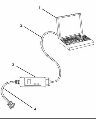
g01121866
Illustration 8
(1) Personal Computer (PC)
(2) Adapter Cable (Computer Serial Port)
(3) Communication Adapter II
(4) Adapter Cable Assembly
Note: Items (2), (3) and (4) are part of the
Communication Adapter II kit.
Use the following procedure in order to connect
the Electronic Service Tool and the Communication
Adapter II.
This document is printed from SPI². Not for RESALE
![]()


![]()
18
KENR9116-01
Troubleshooting Section
1. Turn the keyswitch to the OFF position.
Warning Lamp
2. Connect cable (2) between the “COMPUTER”
end of communication adapter (3) and the RS232
serial port of PC (1).
Lamp check – When the keyswitch is turned to ON,
the lamp will come on for 2 seconds. The lamp will
then go off unless there is an active warning.
Note: The Adapter Cable Assembly (4) is required to
connect to the USB port on computers that are not
equipped with an RS232 serial port.
Flashing – The lamp will be flashing when a
“warning” or a “warning and derate” is active. This
includes low oil pressure.
3. Connect cable (4) between the “DATA LINK” end
of communication adapter (3) and the service tool
connector.
On – The lamp will be on when the shutdown level
has been reached. The “Shutdown” lamp will also
be on.
4. Place the keyswitch in the ON position. If the
Electronic Service Tool and the communication
adapter do not communicate with the Electronic
Control Module (ECM), refer to the diagnostic
procedure Troubleshooting, “Electronic Service
Tool DoesNot Communicate”.
Wait to Start Lamp
Lamp check – When the keyswitch is turned to ON,
the lamp will come on for 2 seconds. The lamp will
then go off unless “Wait to Start” is active.
On – The lamp is on during a “Wait to Start” period.
i03834091
Low Oil Pressure
Indicator Lamps
Lamp check – When the keyswitch is turned to ON,
the lamp will come on for 2 seconds. The lamp will
then go off unless there is an active warning.
Indicator Lamps
On – The lamp will come on when a low oil pressure
event is detected. The “Warning” lamp and the
“Shutdown” lamp may also come on.
Four lamps are available as options. The “Shutdown”
lamp and the “Warning” lamp will normally be installed
in the application. Dedicated optional lamps for other
items may also be installed. The remaining optional
lamps are “Wait to start” and “Low oil pressure”.
Note: On a cold start, when the Electronic Control
Module (ECM) determines that it is necessary for the
glow plugs to be activated prior to starting, a lamp
output will indicate that the operator needs to “Wait
to Start”. It is possible that starting aids may be used
during the cranking of the engine. Starting aids may
be used if the engine has previously been started.
The “Wait to Start” lamp will not be active in these
conditions.
The “Shutdown” lamp and the “Warning” lamp can
also be used to indicate a diagnostic code by use of
the “Flash Code” feature. The “Flash Code” feature
can be used to indicate all active diagnostic codes
and logged diagnostic codes.
Functions of the Lamps
Color of Lamps
Shutdown Lamp
Typically, the “Shutdown” lamp is colored red and the
“Warning” lamp is colored amber. The other lamps
are optional.
Lamp check – When the keyswitch is turned to ON,
the lamp will come on for 2 seconds. The lamp will
then go off unless there is an active warning.
Flashing – The lamp will be flashing when a derate
is active or when a derate is present because of
an active diagnostic code. An example of an active
diagnostic code is “System Voltage High”.
On – The lamp will be on when the shutdown level
in the engine protection strategy has been reached.
The “Warning” lamp will also be on.
This document is printed from SPI². Not for RESALE
![]()
KENR9116-01
19
Troubleshooting Section
Operation of the Indicator Lamps
Table 4
Warning
Lamp
(Alert
Shutdown
Lamp
(Action
Lamp State
Lamp Check
No Faults
Description of the Indication
Engine State
Lamp)
Lamp)
On
On
When the keyswitch is moved to the
ON position, the lamps come on for
a period of 2 seconds and the lamps
will then go off.
The keyswitch is in the ON position but
the engine has not yet been cranked.
Off
On
Off
Off
With the engine in operation, there
are no active warnings, diagnostic
codes or event codes.
The engine is operating with no detected
faults.
Active
Diagnostic
If the warning lamp comes on during
engine operation, this indicates
that an active diagnostic code (an
electrical fault) is present.
The engine is operating normally but
there is one or more faults with the
electronic management system for the
engine.
On
Flashing
Derate
(A derate is
caused by
certain active
codes.)
If the warning lamp comes on and the The engine is operating but there is one
shutdown lamp flashes during engine or more active diagnostic codes that
operation, this indicates that an active have initiated an engine derate.
diagnostic code (an electrical fault) is
present. The diagnostic is sufficiently
serious in order to cause an engine
derate.
Flashing
Off
Warning
(Warning only) during operation of the engine,
the lamp indicates that one or
When the warning lamp flashes
The engine is operating normally.
However, there is one or more of the
monitored engine parameters that are
outside of the range that is acceptable.
more of the warning values for the
engine protection strategy has been
exceeded. However, the value has
not been exceeded to a level that will
cause a derate or a shutdown.
Flashing
Flashing
Off
Warning
(Warning only) Diesel Particulate Filter (DPF).
There is a high soot loading in the
The soot loading in the DPF has
reached 100%. The engine will be
derated. The lamp warns the operator
that the engine needs to be operated in
a mode that promotes regeneration.
Flashing
Derate
(Warning and
Derate)
If both the warning lamp and
shutdown lamp flash during operation one or more of the monitored engine
of the engine, the lamps indicate that parameters is outside of the acceptable
The engine is operating. However,
one or more of the values for the
range. The acceptable range has been
engine protection strategy have been exceeded to a level which requires a
exceeded beyond the level that will
cause an engine derate.
warning and an engine derate.
Flashing
On
On
On
Very high DPF The soot loading in the DPF is high.
soot loading
The soot loading in the DPF has reached
120%. The engine must be operated in
a mode that promotes regeneration.
Engine
Shutdown
If both the warning lamp and the
shutdown lamp come on during
engine operation, this indicates one
of the following conditions.
The engine is either shutdown or an
engine shutdown is imminent. One or
more monitored engine parameters
have exceeded the limit for an engine
shutdown. This pattern of lamps can be
caused by the detection of a serious
active diagnostic code.
1. One or more of the shutdown
values for the engine protection
strategy has been exceeded.
2. A serious active diagnostic code
has been detected.
After a short period of time, the
engine will shut down.
This document is printed from SPI². Not for RESALE
![]()

20
KENR9116-01
Troubleshooting Section
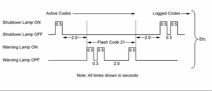
Flash Codes
The “Flash Code” feature is used to flash the code
of all active diagnostic codes and logged diagnostic
codes.
The sequence for the flash code is started by moving
the keyswitch to “Off” and then moving the keyswitch
to “On” twice within a period of three seconds. After
a delay of 2 seconds, the “Shutdown” lamp will flash
once for a period of half a second. This sequence
indicates the start of the active fault codes. After
a further delay of 2 seconds, the “Warning” lamp
will flash repeatedly in order to indicate the active
diagnostic codes. Each flash will be on for half a
second and off for 300 milliseconds. The “Warning”
lamp will remain off for 2 seconds between each digit
of a code. If there is more than one active diagnostic
code, the “Shutdown” lamp will go off for 2 seconds.
The lamp will then come on for a period of half a
second. The “Warning” lamp will go off for a period of
2 seconds before starting the next code. If there are
no active diagnostic codes, the “Warning” lamp will
flash the code “551”. Refer to Troubleshooting Guide,
“No Diagnostic Code Detected”.
As an example, an active diagnostic code of “21” is
indicated by the “Warning” lamp coming on for 500
ms, then off for 300 ms, then on for 500 ms, then off
for 2000 ms, then on for 500 ms and then off.
g01779334
Illustration 9
Timing of the flash codes
After all of the active diagnostic codes have been
displayed, the “Shutdown” lamp will go off for 2
seconds. The “Shutdown” lamp will flash twice in
order to indicate the start of the sequence that will
display the logged diagnostic codes. The process for
flashing logged diagnostic codes is identical to the
process for flashing active diagnostic codes.
Note: If there are no logged codes then the “551”
code should be flashed again.
This document is printed from SPI². Not for RESALE
![]()
![]()
KENR9116-01
21
Troubleshooting Section
After all of the codes have been displayed, the
“Shutdown” lamp will flash 3 times in order to
indicate that there are no further codes. Cycling the
keyswitch twice within a period of 3 seconds will
start the process again. All codes will be displayed in
ascending numerical order.
Note: If an ECM is to be used as a test ECM, “Test
ECM Mode” must be selected on the electronic
service tool before the engine serial number is
entered.
Use the electronic service tool to read the parameters
in the suspect ECM. Record the parameters in
the suspect ECM. Install the flash file into the new
ECM. After the ECM is installed on the engine, the
parameters must be programmed into the new ECM.
Refer to the Troubleshooting Guide, “Diagnostic
Code Cross Reference” for the diagnostic code that
relates to the flash code.
Note: Flash codes are always sent in ascending
numerical order.
Note: When a new ECM is not available, an ECM
can be used from an engine that is not in service.
The ECM must have the same serial number
suffix. Ensure that the replacement ECM and the
part number for the flash file match the suspect
ECM. Be sure to record the parameters from the
replacement ECM. Use the “Copy Configuration ECM
Replacement” function in the electronic service tool.
i04319696
Replacing the ECM
NOTICE
If the flash file and engine application are not matched,
engine damage may result.
NOTICE
Care must be taken to ensure that fluids are contained
during performance of inspection, maintenance, test-
ing, adjusting, and repair of the product. Be prepared
to collect the fluid with suitable containers before
opening any compartment or disassembling any com-
ponent containing fluids.
Perform the following procedure in order to replace
the ECM.
1. Connect the electronic service tool to the
diagnostic connector.
Dispose of all fluids according to local regulations and
mandates.
2. Use the “Copy Configuration ECM Replacement”
function from the electronic service tool. If the
process is successful, proceed to Step 4. If the
“Copy Configuration” failed, proceed to Step 3.
NOTICE
Keep all parts clean from contaminants.
Contaminants may cause rapid wear and shortened
component life.
Note: Record any Logged Faults and Events for your
records.
The engine is equipped with an Electronic Control
Module (ECM). The ECM contains no moving parts.
Follow the troubleshooting procedures in this manual
in order to be sure that replacing the ECM will correct
the fault. Verify that the suspect ECM is the cause
of the fault.
3. Record the following parameters:
•
•
•
Record all of the parameters on the
“Configuration” screen.
Record all of the parameters on the “Throttle
Configuration” screen.
Note: Ensure that the ECM is receiving power
and that the ECM is properly grounded before
replacement of the ECM is attempted. Refer to the
schematic diagram.
Record all of the parameters on the “Mode
Configuration” screen.
• Record the serial numbers of the electronic unit
injectors. The injector serial numbers are shown
on the “Injector Trim Calibration” screen.
A test ECM can be used in order to determine if the
ECM on the engine is faulty. Install a test ECM in
place of the suspect ECM. Install the flash file with
the correct part number into the test ECM. Program
the parameters for the test ECM. The parameters
must match the parameters in the suspect ECM.
Refer to the following test steps for details. If the
test ECM resolves the fault, reconnect the suspect
ECM. Verify that the fault returns. If the fault returns,
replace the ECM.
Note: If the parameters cannot be read, the
parameters must be obtained elsewhere. Some
parameters are stamped on the engine information
plate, but most parameters must be obtained from
the PTMI data on the Perkins web site.
4. Remove power from the ECM.
This document is printed from SPI². Not for RESALE
![]()
![]()
![]()
![]()
![]()
![]()
![]()
22
KENR9116-01
Troubleshooting Section
5. Remove the ECM. Refer to Disassembly and
Assembly, “Electronic Control Module - Remove
and Install”.
Diagnostic Trouble Code – When a fault in the
electronic system is detected, the ECM generates a
diagnostic trouble code. The diagnostic trouble code
indicates the specific fault in the circuitry.
6. Install the replacement ECM. Refer to Disassembly
and Assembly, “Electronic Control Module -
Remove and Install”.
Diagnostic codes can have two different states:
• Active
7. If the replacement ECM is to be used as a test
ECM, select “Test ECM Mode” on the electronic
service tool.
• Logged
Active Code – An active diagnostic code indicates
that an active fault has been detected by the control
system. Active codes require immediate attention.
Always service active codes prior to servicing logged
codes.
8. Download the flash file.
a. Connect the electronic service tool to the
diagnostic connector.
b. Select “WinFlash” from the “Utilities” menu of
the electronic service tool.
Logged Code – Every generated code is stored
in the permanent memory of the ECM. The codes
are logged for 100 operating hours unless a code is
cleared by use of the electronic service tool.
c. Select the downloaded flash file.
9. If necessary, use the electronic service tool to clear
the rating interlock. To clear the rating interlock,
enter the factory password when the electronic
service tool is first connected. Activating the Test
ECM mode will also clear the rating interlock.
Logged codes may not indicate that a repair is
needed. The fault may have been temporary. The
fault may have been resolved since the logging
of the code. If the system is powered, an active
diagnostic trouble code may be generated whenever
a component is disconnected. When the component
is reconnected, the code is no longer active. Logged
codes may be useful to help troubleshoot intermittent
faults. Logged codes can also be used to review the
performance of the engine and the electronic system.
10. Use the electronic service tool to program the
parameters. Perform the following procedure.
a. If the “Copy Configuration” procedure was
successful, use the “Copy Configuration, ECM
Replacement” function to load the configuration
file into the ECM.
i04215569
Sensors and Electrical
Connectors
Note: During the following procedure, factory
passwords may be required.
b. If the “Copy Configuration” procedure failed,
configure the parameters individually. The
parameters should match the parameters from
step 3.
The Electronic Control Module (ECM) and most
of the engine sensors are located on the left side
of the engine. For the 1204E-E44 engine, refer to
Illustration 10. For the remaining sensors that are
attached to the 1204E-E44 engine, refer to Illustration
12. For the 1206E-E66 engine, refer to Illustration 14
. For the remaining sensors that are attached to the
1206E-E66 engine, refer to Illustration 16. For the
sensors and components on the Clean Emissions
Module (CEM), refer to Illustration 18.
Perform the “Fuel System Verification Test”.
11. Check for logged diagnostic codes. Factory
passwords are required to clear logged events.
i03951470
Self-Diagnostics
Note: In the following illustrations, some components
have been removed in order to improve visibility.
The Electronic Control Module (ECM) can detect
faults in the electronic system and with engine
operation. A self-diagnostic check is also performed
whenever power is applied to the ECM.
When a fault is detected, a diagnostic trouble code
is generated. This code conforms to the SAE J1939
standard. An alarm may also be generated.
This document is printed from SPI². Not for RESALE
![]()
KENR9116-01
23
Troubleshooting Section
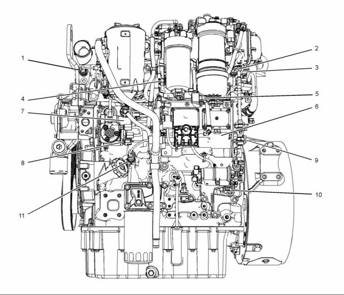
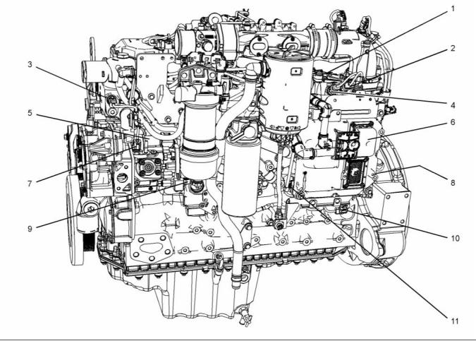
Typical 1204E-E44 Engine
g02479176
Illustration 10
Sensor locations on the left side of a typical 1204E-E44 engine
(1) Coolant temperature sensor
(2) Intake manifold air temperature sensor
(3) Intake manifold pressure sensor
(4) Fuel rail pressure sensor
(5) Water-in-fuel switch
(8) Fuel temperature sensor
(6) Electronic Control Module (ECM)
(7) Suction control valve for the
high-pressure fuel pump
(9) Barometric pressure sensor
(10) Primary speed/timing sensor
(11) Oil pressure sensor
This document is printed from SPI². Not for RESALE
![]()
![]()
24
KENR9116-01
Troubleshooting Section
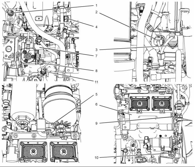
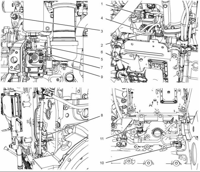
g02479258
Illustration 11
Close up views of sensor locations on the left side of a typical 1204E-E44 engine
(1) Coolant temperature sensor
(2) Intake manifold air temperature sensor
(3) Intake manifold pressure sensor
(4) Fuel rail pressure sensor
(5) Water-in-fuel switch
(8) Fuel temperature sensor
(6) Electronic Control Module (ECM)
(7) Suction control valve for the
high-pressure fuel pump
(9) Barometric pressure sensor
(10) Primary speed/timing sensor
(11) Oil pressure sensor
This document is printed from SPI². Not for RESALE
![]()
![]()
KENR9116-01
25
Troubleshooting Section
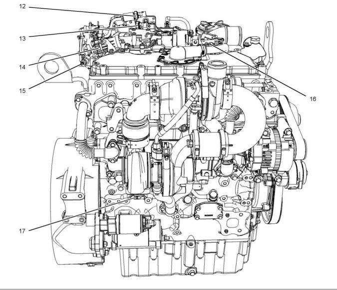
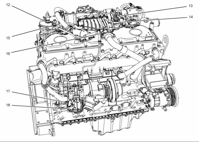
g02481176
Illustration 12
Sensor locations on the right side and the top of a typical 1204E-E44 engine
(12) NRS outlet pressure sensor
(13) NRS inlet pressure sensor
(14) NRS valve
(15) Nox Reduction System (NRS)
temperature sensor
(16) Wastegate regulator
(17) Secondary speed/timing sensor
(18) Exhaust back pressure valve (not
illustrated)
This document is printed from SPI². Not for RESALE
![]()
![]()
26
KENR9116-01
Troubleshooting Section
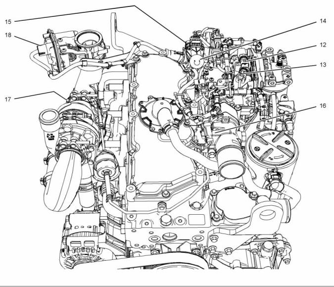
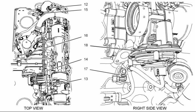
g02481197
Illustration 13
Close up views of sensor locations on the top of a typical 1204E-E44 engine
(12) NRS outlet pressure sensor
(13) NRS inlet pressure sensor
(14) NRS valve
(15) Nox Reduction System (NRS)
temperature sensor (not illustrated)
(16) Wastegate regulator
(17) Secondary speed/timing sensor (not
illustrated)
(18) Exhaust back pressure valve
This document is printed from SPI². Not for RESALE
![]()
![]()
KENR9116-01
27
Troubleshooting Section
1206E-E66 Engine
g02481236
Illustration 14
Sensor locations on the left side of a typical 1206E-E66 engine
(1) Fuel rail pressure sensor
(5) Suction control valve for the
high-pressure fuel pump
(6) Electronic Control Module (ECM)
(7) Fuel temperature sensor
(8) Barometric pressure sensor (not shown)
(9) Water-in-fuel switch
(10) Primary speed/timing sensor
(11) Oil pressure sensor
(2) Intake manifold pressure sensor
(3) Coolant temperature sensor
(4) Intake manifold air temperature sensor
This document is printed from SPI². Not for RESALE
![]()
![]()
28
KENR9116-01
Troubleshooting Section
g02481796
Illustration 15
Close up views of sensor locations on the left side of a typical 1206E-E66 engine
(1) Fuel rail pressure sensor
(5) Suction control valve for the
high-pressure fuel pump
(6) Electronic Control Module (ECM)
(7) Fuel temperature sensor
(8) Barometric pressure sensor
(9) Water-in-fuel switch
(10) Primary speed/timing sensor
(11) Oil pressure sensor
(2) Intake manifold pressure sensor
(3) Coolant temperature sensor
(4) Intake manifold air temperature sensor
This document is printed from SPI². Not for RESALE
![]()
![]()
KENR9116-01
29
Troubleshooting Section
g02483578
Illustration 16
Sensor locations on the right side and the top of a typical 1206E-E66 engine
(12) NRS outlet pressure sensor
(13) Wastegate regulator
(14) NRS valve
(15) NRS inlet pressure sensor
(16) Inlet temperature sensor for the NOx
Reduction System (NRS)
(17) Secondary speed/timing sensor
(18) Exhaust back pressure valve
This document is printed from SPI². Not for RESALE
![]()
![]()
30
KENR9116-01
Troubleshooting Section
g02395457
Illustration 17
Close up views of sensor locations on the right side and the top of a typical 1206E-E66 engine
(12) NRS outlet pressure sensor
(13) Wastegate regulator
(14) NRS valve
(15) NRS inlet pressure sensor
(16) Inlet temperature sensor for the NOx
Reduction System (NRS)
(17) Secondary speed/timing sensor
(18) Exhaust back pressure valve
This document is printed from SPI². Not for RESALE
![]()
![]()
KENR9116-01
31
Troubleshooting Section
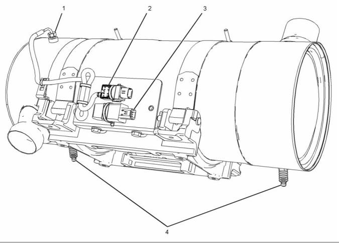
Clean Emissions Module (CEM)
g02095035
Illustration 18
Sensors and components on a typical CEM
(1) Temperature probe for the inlet to the
DPF
(2) Inlet temperature sensor
(3) Aftertreatment identification module
(4) Soot antennas
i04319697
Table 5
Engine Wiring Information
Color Codes for the Harness Wire
Color Code
Color
Color Code
Color
BK
BR
RD
OR
YL
Black
BU
PU
GY
WH
PK
Blue
Harness Wire Identification
Brown
Red
Purple
Gray
Perkins identifies all wires with 11 solid colors. The
circuit number is stamped on the wire at a 25 mm
(1 inch) spacing. Table 5 lists the wire colors and the
color codes.
Orange
Yellow
Green
White
Pink
GN
For example, a wire identification of F730-OR on
the schematic would signify an orange wire with the
circuit number F730. F730-OR identifies the power
supply for the oil pressure sensor.
Note: Always replace a harness wire with the same
gauge of wire and with the same color code.
This document is printed from SPI². Not for RESALE
![]()
![]()

32
KENR9116-01
Troubleshooting Section
Note: In the following diagrams, “Pxxx” signifies a
plug and “Jxxx” signifies a jack.
Schematic Diagrams
1204E-E44 Engine
g02101233
Illustration 19
Schematic diagram of the 1204E-E44 engine connections to the J2 connector on the ECM
This document is printed from SPI². Not for RESALE
![]()
![]()

KENR9116-01
33
Troubleshooting Section
1206E-E66 Engine
g02101353
Illustration 20
Schematic diagram of the 1206E-E66 engine connections to the J2 connector on the ECM
This document is printed from SPI². Not for RESALE
![]()
![]()

34
KENR9116-01
Troubleshooting Section
NOx Reduction System (NRS)
g02101473
Illustration 21
Schematic diagram of the NRS equipment for the 1204E-E44 and 1206E-E66 engines
Clean Emissions Module (CEM)
g02554116
Illustration 22
Schematic diagram of the Clean Emissions Module (CEM)
Wiring for the Application
This document is printed from SPI². Not for RESALE
![]()
![]()
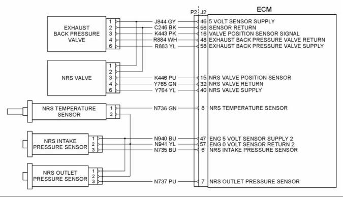
![]()
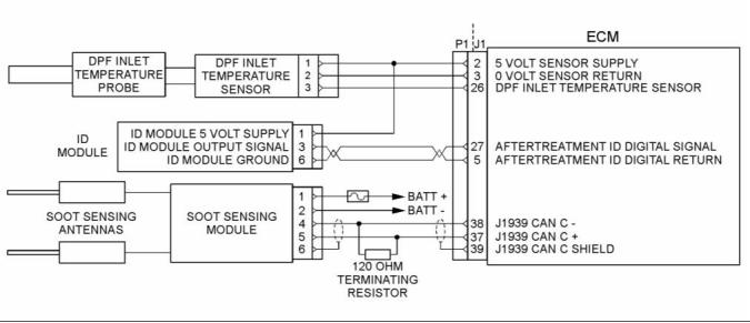
KENR9116-01
35
Troubleshooting Section
g02488496
Illustration 23
Schematic Diagram for a Typical Application
This document is printed from SPI². Not for RESALE
![]()
![]()

36
KENR9116-01
Troubleshooting Section
i04021101
2. Position Tooling (A) around wire (2).
ECM Harness Connector
Terminals
Note: Make sure that the tool stays perpendicular to
the face of the connector (1).
3. Push the tool into the hole for the terminal. Gently
pull the wire in order to remove the terminal from
the rear of the connector (1).
The Electronic Control Module (ECM) uses
connectors that have 70 terminals to interface to the
wiring harness.
4. Remove the Tooling (A) from the wire.
Note: If a terminal must be replaced, part number
2900A016 must be used for 16 and 18 AWG wire.
Part number 28170024 must be used for 14 AWG
wire.
Terminal Insertion
1. Push the terminal into the rear of the connector (1)
until the terminal engages with the locking device.
2. Gently pull on the wire (2) in order to make sure
that the terminal is retained by the locking device.
3. Connect the connector to the ECM and then
tighten the retaining screw to a torque of 6 N·m
(53 lb in).
g01877659
Illustration 24
Layout of the Connector Pins (view from the rear)
Removal and Installation of the
Harness Connector Terminals
Terminal Removal
Table 6
Required Tools
Part
Tool
A
Part Description
Qty
Number
2900A019
Removal Tool (Red)
1
g01877813
Illustration 25
Removal Tool
1. Remove the connector from the ECM. Refer to
Disassembly and Assembly, “Electronic Control
Module - Remove and Install”.
This document is printed from SPI². Not for RESALE
![]()
![]()
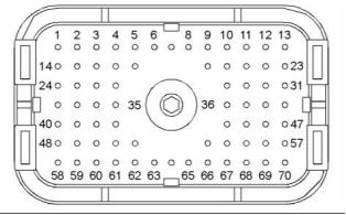
![]()
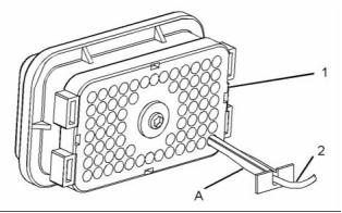
KENR9116-01
37
Troubleshooting Section
Programming Parameters
Note: “Test ECM Mode” can only be activated if
the engine serial number has not already been
programmed during normal operation of the ECM.
If the engine serial number is programmed and the
ECM is not in “Test ECM Mode”, the ECM can never
be used as a test ECM.
i03939853
Programming Parameters
6. Use the “Copy Configuration” feature on the
electronic service tool to program the test ECM.
The electronic service tool can be used to view
certain parameters that can affect the operation of the
engine. The electronic service tool can also be used
to change certain parameters. The parameters are
stored in the Electronic Control Module (ECM). Some
of the parameters are protected from unauthorized
changes by passwords. Parameters that can be
changed have a tattletale number. The tattletale
number is incremented whenever a parameter is
changed.
Note: If the “ECM Replacement” feature cannot be
used, program the test ECM with the values from the
“Customer Specified Parameters Worksheet” and the
values from the System Configuration Parameters.
7. Program the engine serial number into the test
ECM.
Note: The “Test ECM Mode” must be activated
before the engine serial number is programmed into
the ECM.
i03939990
Test ECM Mode
8. Verify that the test ECM eliminates the fault.
When the “Test ECM Mode” is activated, an internal
timer sets a 24 hour clock. This clock will count down
only while the ECM is powered and the keyswitch
is in the ON position. After the ECM has counted
down the 24 hour period, the ECM will exit the “Test
ECM Mode”. The parameters and the engine serial
number will be set.
“Test ECM Mode” is a feature in the software that
can be used to help troubleshoot an engine that may
have a fault in the Electronic Control Module (ECM).
This feature allows a standard ECM to be used as a
test ECM. This feature eliminates the need to stock
a test ECM.
If the test ECM eliminates the fault, the engine can
be released while the “Test ECM Mode” is still active.
1. Search for the la, test flash file for the engine.
Once an ECM has been activated in the “Test ECM
Mode”, the ECM will stay in the “Test ECM Mode”
until the timer times out. If the ECM is used as a test
ECM for more than one engine, the “Test ECM Mode”
must be reactivated. Anytime prior to the “Test ECM
Mode” timing out, the ECM can be reset to 24 hours.
Note: If a newer software version is available for the
engine, install the newest software on the suspect
ECM. If the new software does not eliminate the fault,
continue with this procedure.
2. Use the “Copy Configuration” feature on the
electronic service tool to copy the parameters
from the suspect ECM.
i03898736
Factory Passwords
Note: If the “ECM Replacement” feature cannot
be used, record the programmed values into the
“Customer Specified Parameters Worksheet”. Also
record the system configuration parameters.
NOTICE
3. Disconnect the suspect ECM. Temporarily connect
the test ECM to the engine. Do not mount the test
ECM on the engine.
Operating the engine with a flash file not designed for
that engine will damage the engine. Be sure the flash
file is correct for your engine.
4. Flash program the test ECM with the newest
software that is available.
Note: Factory passwords are provided only to
Perkins authorized distributors.
5. Start the “Test ECM Mode” on the electronic
service tool. Access the feature through the
“Service” menu. The electronic service tool will
display the status of the test ECM and the hours
that are remaining for the “Test ECM Mode”.
Factory passwords are required to perform each of
the following functions:
This document is printed from SPI². Not for RESALE
![]()
![]()
![]()
38
KENR9116-01
Troubleshooting Section
• Program a new Electronic Control Module
(ECM).
Note: You must have the engine serial number in
order to search for the part number of the flash file.
When an ECM is replaced, the system configuration
parameters must be programmed into the new
ECM. A new ECM will allow these parameters to
be programmed once without factory passwords.
After the initial programming, some parameters are
protected by factory passwords.
2. Connect the electronic service tool to the
diagnostic connector.
3. Turn the keyswitch to the ON position. Do not start
the engine.
4. Select “WinFlash” from the “Utilities” menu on the
• Rerate the engine.
electronic service tool.
Rerating may require changing the interlock code,
which is protected by factory passwords.
Note: If WinFlash will not communicate with the
ECM, refer to Troubleshooting, “Electronic Service
Tool Will Not Communicate with ECM”.
• Unlock parameters.
5. Flash program the flash file into the ECM.
Factory passwords are required in order to
unlock certain system configuration parameters.
Refer to Troubleshooting, “System Configuration
Parameters”.
a. Select the engine ECM under the “Detected
ECMs”.
b. Press the “Browse” button in order to select
the part number of the flash file that will be
programmed into the ECM.
• Clear engine events and certain diagnostic
codes.
Most engine events require factory passwords in
order to clear the code from ECM memory. Clear
these codes only when you are certain that the
fault has been corrected. For example, the 190-15
Engine Overspeed requires the use of factory
passwords in order to clear the code from ECM
memory.
c. When the correct flash file is selected, press
the “Open” button.
d. Verify that the “File Values” match the
application. If the file values do not match the
application, search for the correct flash file.
e. When the correct flash file is selected, press
the “Begin Flash” button.
Since factory passwords contain alphabetic
characters, the electronic service tool must be
used to perform these functions. In order to obtain
factory passwords, proceed as if you already have
the password. If factory passwords are needed,
the electronic service tool will request the factory
passwords. The electronic service tool will display the
information that is required to obtain the passwords.
f. The electronic service tool will indicate when
the flash programming has been successfully
completed.
6. Use the electronic service tool to check for
diagnostic code 631-2. If this diagnostic code is
active and the flash file is not being installed in
order to change the engine rating, repeat this
procedure from 1. If this diagnostic code is active
and the flash file is being installed in order to
change the engine rating, factory passwords must
be obtained.
i03898779
Flash Programming
7. Access the “Configuration” screen under the
“Service” menu in order to determine the
parameters that require programming. Look under
the “Tattletale” column. All of the parameters
should have a tattletale of 1 or more. If a parameter
has a tattletale of 0, program that parameter.
Flash Programming – A method of loading a flash
file into the Electronic Control Module (ECM)
The electronic service tool is utilized to flash program
a flash file into the ECM. The flash programming
transfers the flash file from the PC to the ECM.
8. Start the engine and check for proper operation.
Check that there are no active diagnostic codes.
Flash Programming a Flash File
1. Obtain the part number for the new flash file.
Note: If you do not have the part number for the flash
file, use PTMI on the Perkins web site.
This document is printed from SPI². Not for RESALE
![]()
KENR9116-01
39
Troubleshooting Section
“WinFlash” Error Messages
If any error messages are displayed during flash
programming, click on the “Cancel” button in order
to stop the process. Access the “ECM Summary”
information through the “Information” menu. Ensure
that you are programming the correct flash file for
your engine.
If a 630-2 diagnostic trouble code is displayed after
flash programming, a required parameter is missing.
Program the missing parameter.
i03859293
g02132457
Injector Code - Calibrate
Illustration 27
Sequence for recording the injector code
The electronic service tool is used to load the injector
codes into the ECM.
Injector codes are codes that are 30 hexadecimal
characters in length that are supplied with each
injector. The code is on a plate on the top of the
injector and a card is also included in the packaging
for the injector. The code is used by the Electronic
Control Module (ECM) to balance the performance
of the injectors.
The injector codes must be loaded into the ECM if
any of the following conditions occur:
• An electronic unit injector is replaced.
• The ECM is replaced.
• Diagnostic code 268-2 is active.
• Electronic unit injectors are exchanged between
cylinders.
Note: Diagnostic code 268-2 will also become active
if the engine serial number, FLS or FTS are not
entered into the ECM.
If the ECM is replaced, the injector codes are
normally transferred to the new ECM as part of
the “Copy Configuration” procedure. If the “Copy
Configuration” procedure fails, the injector codes
must be loaded manually.
Installing Injector Codes
Note: The injector code is located on the electronic
unit injector.
g02132456
1. Record the injector code for each electronic unit
Illustration 26
injector.
Typical label with an injector code
2. Connect the electronic service tool to the
diagnostic connector. Refer to Troubleshooting,
“Electronic Service Tools”.
3. Turn the keyswitch to the ON position.
4. Select the following menu options on the electronic
service tool:
• Service
• Calibrations
This document is printed from SPI². Not for RESALE
![]()
![]()
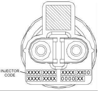
![]()
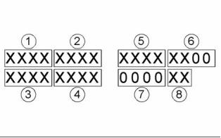
40
KENR9116-01
Troubleshooting Section
Mode Selection Number
• Injector Trim Calibration
5. Select the appropriate cylinder.
6. Click on the “Change” button.
This parameter is a non-programmable parameter
that represents the number of possible combinations
of switch positions. This parameter is based on the
value that is programmed into the “Number of Switch
Inputs” parameter.
7. Input the applicable injector code that was
recorded in Test Step 1.
Mode Selection Switch Input 2 and
Mode Selection Switch Input 1
8. Click on the “OK” button.
The injector code is loaded into the ECM.
The number of these non-programmable parameters
that are visible depends on the value that is
programmed into the “Number of Switch Inputs”
parameter. “Open” signifies that the switch is in the
OFF position. “Ground” signifies that the switch is
in the ON position.
9. Repeat the procedure for each cylinder, as
required.
Exchanging Electronic Unit Injectors
Exchanging electronic unit injectors can help
determine if a combustion problem is in the electronic
unit injector or in the cylinder. If two electronic unit
injectors that are currently installed in the engine are
exchanged between cylinders, the injector codes
must also be exchanged. Press the “Exchange”
button at the bottom of the “Injector Trim Calibration”
screen on the electronic service tool. Select the two
electronic unit injectors that will be exchanged and
press the “OK” button. The tattletale for the electronic
unit injectors that were exchanged will increase by
one.
Rating Enabled
If “Yes” is selected on the drop-down menu, the
ECM is programmed to use the values in the “Rating
Number”, “Throttle 1 Droop Percentage”, “Throttle 2
Droop Percentage” and “TSC1 Droop Percentage”
for the given combination of switch positions.
Table 8
Values
Default
Factory Password
Yes
No
No
No
i04124470
Mode Switch Setup
High Idle Speed
The “High Idle Speed” is the maximum engine rpm.
The Mode Switches can be used to change the
performance characteristics of the engine. The
electronic service tool is used to program the
characteristics. Select the “Service” drop-down
menu and then select “Engine Operating Mode
Configuration”. A maximum of two switches can be
used. “Switch 1” is connected to J1:62 Mode Switch
1. “Switch 2” is connected to J1:64 Mode Switch 2.
The other contact on both switches is connected to
J1:18 Switch Return.
Table 9
Minimum
Maximum
Default
1800 rpm
2800 rpm
2420 rpm
Rating Number
This parameter is the engine rating that is used by
the Electronic Control Module (ECM) for a given
combination of switch positions. There is a maximum
of four ratings in a flash file.
Number of Switch Inputs
Table 10
This configuration parameter is the total number
of switches that are used. The switches can be
individual switches or a multiple rotary switch.
Range
Default
Factory
Password
1 to the
maximum
1
No
Table 7
Range
Default
number of ratings
in the currently
installed Flash
File
0 to 2
0
This document is printed from SPI². Not for RESALE
![]()
![]()

![]()

KENR9116-01
41
Troubleshooting Section
Rated Speed (RPM)
Table 15
Range
Default
Factory
Password
This parameter represents the engine speed that is
selected when the mode switch or the mode switches
are in a particular position.
0 to 10 percent
5.0%
No
Table 11
TSC1 Droop Percentage
Range
Default
Factory
Password
This parameter represents the amount of droop that
is applied to the “Torque Speed Control 1(TSC1)”
input.
“Programmed
Low Idle” to
“Programmed
High Idle”
2100 rpm
No
Table 16
Range
Default
Factory
Engine High Idle Speed (RPM)
Password
0 to 10 percent
5.0%
No
This parameter represents a maximum of 112% of the
rated speed that is selected when the mode switch or
the mode switches are in a particular position.
i04105410
Throttle Setup
Table 12
Range
Default
Factory
Password
“1800 to 2800
rpm”
112% of rated
speed
No
There are two separate channels for throttle input.
The two channels can have any combination of a
digital throttle that uses a Pulse Width Modulated
(PWM) signal, an analog throttle or a multi-position
switched throttle.
Governor Type
This parameter represents the mode of operation of
the governor that is installed on the engine.
The Electronic Control Module (ECM) must be
programmed with the type of throttle input that is
being used in either position. From the menu, select
“Services”. On the “Services” screen, select “Throttle
Configuration”. Select the type of throttle from the
following list:
Table 13
Range
Default
Factory
Password
“Min/Max speed
(rpm)” or “All
Speed”
All Speed
No
• No throttle
• Analog throttle
Throttle 1 Droop Percentage
• PWM throttle
This parameter represents the amount of droop that
is applied to the “Throttle 1” input.
• Multi-position throttle switch
The Electronic Control Module (ECM) must be
programmed for throttle arbitration. This parameter
determines which throttle input has priority. From the
menu, select “Services”. On the “Services” screen,
select “Throttle Arbitration”. Select the arbitration
method from the following list:
Table 14
Range
Default
Factory
Password
0 to 10 percent
5.0%
No
• Highest Wins
• Lowest Wins
• Manual Switch
Throttle 2 Droop Percentage
This parameter represents the amount of droop that
is applied to the “Throttle 2” input.
The default setting for throttle arbitration is “Highest
Wins”.
This document is printed from SPI². Not for RESALE
![]()


42
KENR9116-01
Troubleshooting Section
Lower Position Limit
This parameter is the minimum throttle percentage
that will be interpreted by the ECM as zero throttle.
This parameter is used with the value of initial lower
position limit to make an allowance for manufacturing
tolerances between different pedals.
Table 18
Range
Default
0 to 100%
10%
Initial Lower Position Limit
This parameter is the maximum throttle percentage
that will be interpreted by the ECM as zero throttle.
This parameter is used with the value of the lower
position limit to make an allowance for manufacturing
tolerances between different pedals.
g01785156
Illustration 28
Table 19
Typical Range of Throttle
Range
Default
(1) Lower Diagnostic Limit (Default=5)
(2) Lower Position Limit (Default=10)
0 to 100%
20%
(3) Initial Lower Position (Default=20)
(4) Idle Validation Minimum Off Threshold (Default=21)
(5) Idle Validation Maximum On Threshold (Default=25)
(6) Lower Dead Zone % (Default=8)
Idle Validation
(7) Upper Dead Zone % (Default=5)
(8) Initial Upper Position (Default=70)
(9) Upper Position Limit (Default=85)
All analog throttles and digital throttles can have an
idle validation switch. If this parameter is programmed
to “Yes”, the ECM will look for this switch input on pin
J1:22 for Idle Validation Switch 1 (IVS1) and J1:40
for Idle Validation Switch 2 (IVS2).
(10) Upper Diagnostic Limit (Default=95)
Analog throttles and digital throttles require additional
programming. If a multi-position switch is selected,
additional parameters must be programmed.
Refer to the Troubleshooting Guide, “Multiposition
Switch Setup”. If an analog throttle or a digital
throttle is selected, the following parameters can be
programmed into the ECM.
Table 20
Values
Default
No
Yes
No
Lower Diagnostic Limit
Idle Validation Minimum Off (Open)
Threshold
This parameter is the minimum throttle percentage
that should be detected by the ECM in normal
operation when the pedal is in the “off” position. A
value below this limit will generate a short circuit
diagnostic code. The range of this diagnostic
detection area is from 0 percent to the programmed
value for the lower position limit.
This parameter is the minimum throttle percentage
that will be detected by the ECM when the IVS is ON
(Closed).
If the ECM detects a throttle percentage below this
value with the idle validation switch OFF (Open),
a fault code will be generated and the engine will
remain at idle.
Table 17
Range
Default
0 to 100%
5%
Refer to Table 21 and Table 22.
This document is printed from SPI². Not for RESALE
![]()
![]()
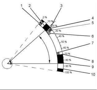
![]()
![]()
![]()

KENR9116-01
43
Troubleshooting Section
Table 21
Throttle Position
Sensor (TPS)
Idle Validation Switch
(IVS)
Throttle Demand
Output
Fault Status
Raise IVS fault
No fault
Comment
TPS< IVS Min OFF
OFF
Minimum Position
Force throttle demand
to minimum
TPS< IVS Min OFF
ON
Throttle Position
Normal operation
Table 22
Range
Default
0 to 100%
21%
Idle Validation Maximum On
(Closed) Threshold
This parameter is the maximum throttle percentage
that will be detected by the ECM when the idle
validation switch (IVS) is OFF (Open) . When the idle
validation switch is OFF (Open) and the ECM detects
a signal that is higher than the programmed value for
IVS Max ON, the ECM will generate a fault code and
the engine will remain at idle.
Refer to Table 23 and Table 24.
Table 23
Throttle Position
Sensor (TPS)
Idle Validation Switch
(IVS)
Throttle Demand
Output
Fault Status
Comment
TPS> IVS Max ON
TPS< IVS Min Off
OFF
ON
Throttle Position
Minimum Position
No fault
Normal operation
Raise IVS fault
Force throttle demand
to minimum
Table 24
Table 26
Range
Default
Range
Default
0 to 100%
25%
0 to 100%
5%
Lower Dead Zone
Initial Upper Position Limit
This parameter is a throttle range above the initial
lower position limit before the engine will increase
in rpm.
This parameter is the minimum throttle percentage
that will be interpreted by the ECM as full throttle.
This parameter is used with the value of the upper
position limit to make an allowance for manufacturing
tolerances between different pedals.
Table 25
Range
Default
Table 27
0 to 100%
5%
Range
Default
0 to 100%
70%
Upper Dead Zone
This parameter is a throttle range that is below the
initial upper position limit that does not allow the
engine speed to increase.
Upper Position Limit
This parameter is the maximum throttle percentage
that will be interpreted by the ECM as full throttle. This
parameter is used with the value of the initial upper
position limit to make an allowance for manufacturing
tolerances between different pedals.
This document is printed from SPI². Not for RESALE
![]()

![]()

![]()
![]()
![]()
![]()
44
KENR9116-01
Troubleshooting Section
Table 28
Input 4, Input 3, Input 2, Input 1
Range
Default
The number of these non-programmable parameters
that are visible depends on the value that is
programmed into the “Number of Switch Inputs”
parameter. “Open” signifies that the switch is in the
OFF position. “Ground” signifies that the switch is
in the ON position.
0 to 100%
85%
Upper Diagnostic Limit
This parameter is the minimum throttle percentage
that is detected by the ECM in normal operation when
the pedal is in the maximum position. A value above
this limit will generate an open circuit diagnostic
code. The range of this diagnostic detection area is
from the programmed value of the upper position
limit to 100 percent.
Physical Position Enabled
If “Yes” is selected from the drop-down menu,
the ECM sets the engine rpm to the value that
is programmed into the “Engine Speed” for the
configuration of the switches that is defined for that
Physical Position.
Table 29
Range
Default
Table 31
0 to 100%
95%
Value
Default
No
No
Yes
i04105411
Multiposition Switch Setup
Logical Position
The Logical Position is the order that is required by
the user for a unique Physical Position.
Note: The multi-position throttle switch can only be
enabled if the optional PTO switches are not installed.
Table 32
The multi-position throttle switch is an optional
throttle input. A maximum of four switches can be
used. Four switches will allow a maximum of 16
speeds to be selected.
Range with Four
Switches
Default
1 to 16
1
Engine Speed (in RPM)
If an optional intermediate engine speed switch is
installed, the multi-position throttle switch can have a
maximum of three switches. Three switches will allow
a maximum of eight speeds to be selected.
The “Engine Speed” is the programmed engine rpm
for a particular position of the multi-position throttle
switch.
When the multi-position switch is selected as the
“Throttle Type” on the “Throttle Configuration Screen”
of the electronic service tool, additional information
is required.
If the ECM detects a switch combination that
has been configured as “No”, a fault code will be
generated. In this situation, the ECM will ignore the
multi-position switch until the keyswitch is cycled
through OFF and ON.
Number of Switch Inputs
Table 33
This parameter is the total number of switches that
will be used. The switches may be individual switches
or a ganged rotary switch.
Range
Default
Programmed Low Idle to
Programmed High Idle
0
Table 30
Range
Default
1 to 4
0
Physical Position
This parameter is non-programmable. The parameter
is used to signify the position of the rotary switch.
This document is printed from SPI². Not for RESALE
![]()
![]()
![]()
![]()


KENR9116-01
45
Troubleshooting Section
Customer Specified
Speed Control
Parameters
Low Idle Speed
The “Low Idle Speed” is the minimum engine rpm.
i04317190
Customer Specified
Table 36
Parameters
Minimum
Maximum
Default
700 rpm
1200 rpm
750 rpm
Engine Configuration Parameters
Customer specified parameters allow the engine to
be configured to the exact needs of the application.
Ether Solenoid Configuration
Customer parameters may be changed repeatedly as
operational requirements change.
The ether solenoid configuration defines the
presence of a solenoid for an ether starting aid.
Customer passwords are required in order to change
this parameter.
The following information is a brief description of
the customer specified parameters. The following
parameter values are included with the descriptions:
Table 37
• Minimum
• Maximum
• Default
Value
Default
Not Installed
Not Installed
Continuous Flow Solenoid
Engine Idle Shutdown
ECM Identification Parameter
The Engine Idle Shutdown parameters define the
engine response when the keyswitch is turned to the
OFF position.
Equipment ID
“Equipment ID” is the identification of the equipment
that is assigned by the customer. The “Equipment ID”
is only for reference by the customer. The “Equipment
ID” is not required by the Electronic Control Module
(ECM).
Minimum Ambient Air Temperature
Table 38
Value
Default
Table 34
0 to 29 Degrees C
0 Degrees C
Value
Default
Maximum Ambient Air Temperature
17 digits
The available characters
are dependent on the
service tool that is
being used.
Not programmed
Table 39
Value
Default
30 to 100 Degrees C
30 Degrees C
Engine Rating Parameter
Shutdown Enable Status
Rating Number
Table 40
The rating number is the selected rating within a
power rating family. The flash file defines the power
rating family. The flash file can contain one to four
ratings. The rating number defines the power rating
that is used within the power rating family.
Value
Default
Enabled
Disabled
Disabled
Table 35
Minimum
Maximum
Default
1
4
1
This document is printed from SPI². Not for RESALE
![]()

![]()
![]()

![]()
![]()

46
KENR9116-01
Troubleshooting Section
Shutdown Delay Time
• “Throttle Lock Increment Speed Ramp Rate”
Table 41
• “Throttle Lock Engine Set Speed Increment”
Value
Default
Table 45
1 to 60 minutes
5 minutes
Value
Default
Not Installed
Installed
Ambient Temperature Override Enable
Status
Not Installed
PTO Mode
Table 42
Value
Default
PTO mode can be configured to operate in either
Set/Resume mode or Ramp up/Ramp down mode.
Set/Resume mode allows the engine speed to be
controlled by the operator through switch inputs.
This mode allows two specific speeds to be set
and stored in the ECM. A speed can be selected
or the previously selected speed can be resumed.
Adjustments in engine speed can then be made via
the raise and lower switch inputs. Ramp up/Ramp
down mode only allows the engine speed to be raised
or lowered via switch inputs at a desired ramp rate.
The “Set” and “Resume” functions are disabled.
Enabled
Disabled
Disabled
Air Shutoff
Air Shutoff
The Air Shutoff parameter defines whether an air
shutoff valve is installed in the air inlet for the engine.
Table 43
Table 46
Value
Default
Value
Default
Enabled
Disabled
Disabled
Ramp Up/Ramp Down
Set/Resume
Set/Resume
Multiple Engines on J1939
Throttle Lock Engine Set Speed 1
Engine Location
The “Throttle Lock Engine Set Speed 1” parameter is
one of the engine speeds that can be selected in the
PTO Set/Resume mode.
In a situation where multiple engines communicate on
one J1939 channel, the Engine Location parameter
defines the identity of each engine in the set.
Table 47
Minimum
Maximum
Default
Table 44
Value
Default
Low idle speed
Rated speed
700
Engine #1
Engine #2
Engine #3
Engine #4
Engine #5
Throttle Lock Engine Set Speed 2
Engine #1
The “Throttle Lock Engine Set Speed 1” parameter is
one of the engine speeds that can be selected in the
PTO Set/Resume mode.
PTO and Throttle Lock Parameters
Table 48
Minimum
Maximum
Default
Throttle Lock Feature Installation Status
Low idle speed
Rated speed
700
Note: PTO and a multi-position throttle switch cannot
be installed at the same time.
Throttle Lock Increment Speed Ramp
Rate
The “Throttle Lock Feature Installation Status” is
used to turn on the throttle lock features. When this
parameter is changed to “Installed”, the following
parameters are active and the parameters can be
programmed.
The “Throttle Lock Increment Speed Ramp Rate”
parameter is the rate of engine acceleration when the
PTO switch is held in the ACCELERATE position. If
this parameter is set to “0”, the feature is turned off.
• “PTO engine Speed Setting”
This document is printed from SPI². Not for RESALE
![]()
![]()


![]()
![]()
KENR9116-01
47
Troubleshooting Section
Table 49
Table 53
Minimum
0 rpm/sec
Maximum
Default
Value
Default
600 rpm/sec
400 rpm/sec
Disabled
Enabled
Enabled
Throttle Lock Decrement Speed Ramp
Rate
Monitoring Mode Derates
The “Monitoring Mode Derates” parameter controls
the amount of derate that is associated with the
engine monitoring feature. When this feature is
enabled and a diagnostic code with an appropriate
FMI is detected, the engine will be derated.
The “Throttle Lock Decrement Speed Ramp Rate”
parameter is the rate of engine deceleration when
the PTO switch is held in the DECELERATE position.
If this parameter is set to “0”, the feature is turned off.
Table 50
Table 54
Minimum
Maximum
Default
Value
Default
0 rpm/sec
600 rpm/sec
400 rpm/sec
Disabled
Enabled
Enabled
Throttle Lock Engine Set Speed
Increment
Limp Home Desired Engine Speed
The “Throttle Lock Engine Set Speed Increment”
parameter controls the increase in engine speed
when the PTO switch is briefly operated to
ACCELERATE. If this parameter is set to “0”, the
feature is turned off.
The “Limp Home Desired Engine Speed” parameter
is the maximum speed of the engine when the engine
has been derated.
Table 55
Minimum
Maximum
Default
Table 51
700 rpm
1800 rpm
1200 rpm
Minimum
Maximum
Default
0 rpm
200 rpm
10 rpm
Engine Acceleration Rate
Throttle Lock Engine Set Speed
Decrement
The “Engine Acceleration Rate” parameter is the
acceleration rate for the engine under normal
operating conditions. A setting of “0” disables this
function.
The “Throttle Lock Engine Set Speed Decrement”
parameter controls the decrease in engine speed
when the PTO switch is briefly operated to
DECELERATE. If this parameter is set to “0”, the
feature is turned off.
Table 56
Minimum
Maximum
Default
0 rpm
65503 rpm/sec
0 rpm/sec
Table 52
Minimum
Maximum
Default
Engine Speed Decelerating Ramp Rate
0 rpm
200 rpm
10 rpm
The “Engine Speed Decelerating Ramp Rate”
parameter is the deceleration ramp rate for the
engine under normal operating conditions. A setting
of “0” disables this function.
Miscellaneous
Monitoring Mode Shutdowns
Table 57
Minimum
Maximum
Default
The “Monitoring Mode Shutdowns” parameter
controls the shutdown feature that is associated with
the engine monitoring feature. When this feature is
enabled and a diagnostic code with a “-31” suffix is
detected, the engine will be shut down.
0 rpm
65503 rpm/sec
0 rpm/sec
Intermediate Engine Speed
The “Intermediate Engine Speed” is a selectable
engine speed that is between the low idle speed and
the high engine speed. This parameter is disabled
when the value is set to 0 rpm.
This document is printed from SPI². Not for RESALE
免费热线
400-100-8969 15088860848
400-100-8969 15088860848
机组销售
0574-26871589 15267810868
0574-26871589 15267810868
配件销售
0574-26886646 15706865167
0574-26886646 15706865167
维修热线
0574-26871569 18658287286
0574-26871569 18658287286
手机端

微信公众号