 English
 Espaol
 Franais
 阿拉伯
阿拉伯 中文(简)
中文(简) Deutsch
 Italiano
 Português
 日本
日本 韩国
韩国 български
 hrvatski
 esky
esky Dansk
Dansk Nederlands
 suomi
suomi Ελληνικ
 印度
印度 norsk
norsk Polski
 Roman
Roman русский
 Svenska
 珀金斯Perkins1206E-E66TA操作保养,珀金斯Perkins1206E-E66TA操作保养技术支持中心,珀金斯Perkins1206E-E66TA操作保养代理商,珀金斯Perkins1206E-E66TA操作保养销售服务中心,珀金斯Perkins1206E-E66TA操作保养价格规格资料查询,宁波日昕动力科技有限公司

珀金斯Perkins1206E-E66TA操作保养(英文)
详细描述
Operation and
Maintenance
Manual
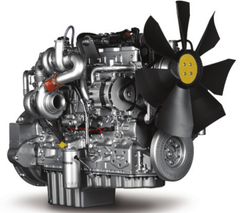
1206E-E66TA Industrial Engine
BK (Engine)
This document is printed from SPI². Not for RESALE
![]()
![]()
![]()
![]()
Important Safety Information
Most accidents tha t involve produc t op eration, ma intena nc e and repair are caus ed by failure to
ob serve basic safety rules or precautions . An accident can often be avoided by recog nizing pote ntially
ha za rdous situations before an accident oc curs . A person mus t be alert to pote ntial ha za rds. This
person should also ha ve the ne cessary training, skills and tools to perform the se func tions properly.
Improper operation, lubrication, maintenance or repair of this product can be dangerous and
could result in injury or death.
Do not operate or perform any lubrication, maintenance or repair on this product, until you have
read and understood the operation, lubrication, maintenance and repair information.
Sa fety precautions and warning s are provided in this ma nua l and on the produc t. If the se ha za rd
warning s are not he eded, bod ily injury or death could oc cur to you or to othe r persons .
The ha za rds are identified by the “Safety Alert Symb ol” and followed by a “Signa l Word” suc h as
“DANGER”, “WARNING” or “CAUTION”. The Sa fety Alert “WARNING” label is shown below.
The me aning of this safety alert symb ol is as follows:
Attention! Become Alert! Your Safety is Involved.
The me ssage tha t appears und er the warning explains the ha za rd and can be either written or
pictorially presente d.
Op erations tha t ma y caus e produc t dama ge are identified by “NOTICE” labels on the produc t and in
this pub lication.
Perkins cannot anticipate every possible circumstance that might involve a potential hazard. The
warnings in this publication and on the product are, therefore, not all inclusive. If a tool, procedure,
work method or operating technique that is not specifically recommended by Perkins is used,
you must satisfy yourself that it is safe for you and for others. You should also ensure that the
product will not be damaged or be made unsafe by the operation, lubrication, maintenance or
repair procedures that you choose.
The informa tion, specifications , and illustrations in this pub lication are on the basis of informa tion tha t
was available at the time tha t the pub lication was written. The specifications , torque s, pressure s,
me asure me nts , adjustme nts , illustrations , and othe r items can cha ng e at any time. These cha ng es can
affect the service tha t is given to the produc t. Ob tain the comp lete and mos t current informa tion before
you start any job. Pe rkins dealers or Pe rkins distributors ha ve the mos t current informa tion available.
When replacement parts are required for this
product Perkins recommends using Perkins
replacement parts.
Failure to heed this warning can lead to prema-
ture failures, product damage, personal injury or
death.
This document is printed from SPI². Not for RESALE
![]()
![]()
![]()
SEBU8603-01
3
Table of Contents
Table of Contents
Maintenance Interval Schedule ............................ 78
Warranty Section
Foreword ................................................................. 4
Warranty Information ........................................... 110
Safety Section
Reference Information Section
Safety Messages .................................................... 5
General Hazard Information ................................... 8
Burn Prevention ..................................................... 11
Fire Prevention and Explosion Prevention ............ 12
Crushing Prevention and Cutting Prevention ........ 14
Mounting and Dismounting ................................... 14
High Pressure Fuel Lines ..................................... 14
Before Starting Engine .......................................... 16
Engine Starting ..................................................... 16
Engine Stopping ................................................... 16
Electrical System .................................................. 17
Engine Electronics ................................................ 18
Reference Materials ............................................. 114
Index Section
Index .................................................................... 115
Product Information Section
Model Views ......................................................... 20
Product Identification Information ........................ 27
Operation Section
Lifting and Storage ................................................ 29
Gauges and Indicators .......................................... 32
Features and Controls .......................................... 34
Engine Diagnostics ............................................... 45
Engine Starting ..................................................... 51
Engine Operation .................................................. 54
Engine Stopping ................................................... 56
Cold Weather Operation ....................................... 58
Maintenance Section
Refill Capacities .................................................... 62
Maintenance Recommendations .......................... 76
This document is printed from SPI². Not for RESALE
![]()
![]()
4
SEBU8603-01
Foreword
Foreword
Recommended service should be performed at the
appropriate intervals as indicated in the Maintenance
Interval Schedule. The actual operating environment
of the engine also governs the Maintenance Interval
Schedule. Therefore, under extremely severe,
dusty, wet or freezing cold operating conditions,
more frequent lubrication and maintenance than is
specified in the Maintenance Interval Schedule may
be necessary.
Literature Information
This manual contains safety, operation instructions,
lubrication and maintenance information. This
manual should be stored in or near the engine area
in a literature holder or literature storage area. Read,
study and keep it with the literature and engine
information.
The maintenance schedule items are organized for
a preventive maintenance management program. If
the preventive maintenance program is followed, a
periodic tune-up is not required. The implementation
of a preventive maintenance management program
should minimize operating costs through cost
avoidances resulting from reductions in unscheduled
downtime and failures.
English is the primary language for all Perkins
publications. The English used facilitates translation
and consistency.
Some photographs or illustrations in this manual
show details or attachments that may be different
from your engine. Guards and covers may have
been removed for illustrative purposes. Continuing
improvement and advancement of product design
may have caused changes to your engine which are
not included in this manual. Whenever a question
arises regarding your engine, or this manual, please
consult with your Perkins dealer or your Perkins
distributor for the latest available information.
Maintenance Intervals
Perform maintenance on items at multiples of
the original requirement. We recommend that the
maintenance schedules be reproduced and displayed
near the engine as a convenient reminder. We also
recommend that a maintenance record be maintained
as part of the engine's permanent record.
Safety
Your authorized Perkins dealer or your Perkins
distributor can assist you in adjusting your
maintenance schedule to meet the needs of your
operating environment.
This safety section lists basic safety precautions.
In addition, this section identifies hazardous,
warning situations. Read and understand the basic
precautions listed in the safety section before
operating or performing lubrication, maintenance and
repair on this product.
Overhaul
Major engine overhaul details are not covered in
the Operation and Maintenance Manual except
for the interval and the maintenance items in that
interval. Major repairs should only be carried out by
Perkins authorized personnel. Your Perkins dealer
or your Perkins distributor offers a variety of options
regarding overhaul programs. If you experience
a major engine failure, there are also numerous
after failure overhaul options available. Consult with
your Perkins dealer or your Perkins distributor for
information regarding these options.
Operation
Operating techniques outlined in this manual are
basic. They assist with developing the skills and
techniques required to operate the engine more
efficiently and economically. Skill and techniques
develop as the operator gains knowledge of the
engine and its capabilities.
The operation section is a reference for operators.
Photographs and illustrations guide the operator
through procedures of inspecting, starting, operating
and stopping the engine. This section also includes a
discussion of electronic diagnostic information.
California Proposition 65 Warning
Diesel engine exhaust and some of its constituents
are known to the State of California to cause cancer,
birth defects, and other reproductive harm. Battery
posts, terminals and related accessories contain lead
and lead compounds. Wash hands after handling.
Maintenance
The maintenance section is a guide to engine care.
The illustrated, step-by-step instructions are grouped
by service hours and/or calendar time maintenance
intervals. Items in the maintenance schedule are
referenced to detailed instructions that follow.
This document is printed from SPI². Not for RESALE
![]()
SEBU8603-01
5
Safety Section
Safety Messages
Safety Section
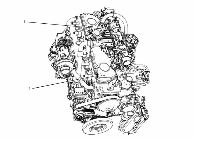
The Universal Warning label (1) is located in two
positions. The warning labels are located on the font
right side of the valve mechanism cover and located
on the side of the NOx reduction system (NRS).
i04220089
Safety Messages
There may be several specific warning signs on your
engine. The exact location and a description of the
warning signs are reviewed in this section. Please
become familiar with all warning signs.
Ensure that all of the warning signs are legible. Clean
the warning signs or replace the warning signs if
the words cannot be read or if the illustrations are
not visible. Use a cloth, water, and soap to clean
the warning signs. Do not use solvents, gasoline, or
other harsh chemicals. Solvents, gasoline, or harsh
chemicals could loosen the adhesive that secures the
warning signs. The warning signs that are loosened
could drop off the engine.
Replace any warning sign that is damaged or
missing. If a warning sign is attached to a part of the
engine that is replaced, install a new warning sign on
the replacement part. Your Perkins distributor can
provide new warning signs.
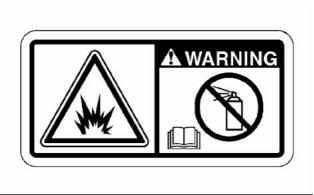
(1) Universal Warning
Do not operate or work on this equipment unless
you have read and understand the instructions
and warnings in the Operation and Maintenance
Manuals. Failure to follow the instructions or
heed the warnings could result in serious injury
or death.
g01154807
Illustration 1
Typical example
This document is printed from SPI². Not for RESALE
![]()
![]()
![]()
![]()
![]()
6
SEBU8603-01
Safety Section
Safety Messages
g02382617
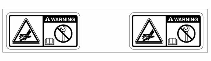
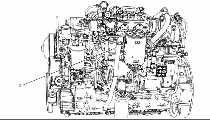
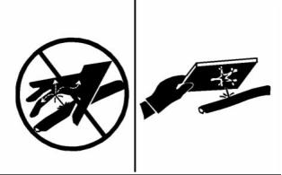
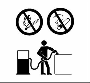
Illustration 2
Typical example
(1) Universal warning
(2) Hand (High Pressure)
Contact with high pressure fuel may cause fluid
penetration and burn hazards. High pressure fu-
el spray may cause a fire hazard. Failure to fol-
low these inspection, maintenance and service in-
structions may cause personal injury or death.
This document is printed from SPI². Not for RESALE
![]()
![]()
![]()
![]()
SEBU8603-01
7
Safety Section
Safety Messages
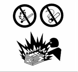
g02382677
Illustration 3
Typical example
The warning label for the Hand (High Pressure)
(3) is a wrap around label that is installed on the
high-pressure fuel line.
g02382618
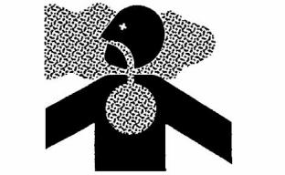
Illustration 4
Typical example
Ether Warning
Do not use aerosol types of starting aids such as
ether. Such use could result in an explosion and
personal injury.
This document is printed from SPI². Not for RESALE
![]()
![]()
![]()
![]()
![]()
8
SEBU8603-01
Safety Section
General Hazard Information
• Vent the engine exhaust to the outside when the
engine is operated in an enclosed area.
• If the engine is not running, do not release the
secondary brake or the parking brake systems
unless the vehicle is blocked or unless the vehicle
is restrained.
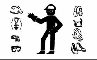
• Wear a hard hat, protective glasses, and other
protective equipment, as required.
• When work is performed around an engine that is
operating, wear protective devices for ears in order
to help prevent damage to hearing.
g01154809
Illustration 5
•
•
Do not wear loose clothing or jewelry that can snag
on controls or on other parts of the engine.
Typical example
An ether warning label will be installed on the air
cleaner or close to the air cleaner. The location will
depend on the application.
Ensure that all protective guards and all covers are
secured in place on the engine.
• Never put maintenance fluids into glass containers.
Glass containers can break.
i03566024
General Hazard Information
• Use all cleaning solutions with care.
• Report all necessary repairs.
Unless other instructions are provided, perform the
maintenance under the following conditions:
• The engine is stopped. Ensure that the engine can
not be started.
• The protective locks or the controls are in the
applied position.
• Engage the secondary brakes or parking brakes.
• Block the vehicle or restrain the vehicle before
maintenance or repairs are performed.
g00104545
• Disconnect the batteries when maintenance
is performed or when the electrical system is
serviced. Disconnect the battery ground leads.
Tape the leads in order to help prevent sparks.
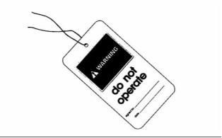
Illustration 6
Attach a “Do Not Operate” warning tag or a similar
warning tag to the start switch or to the controls
before the engine is serviced or before the engine is
repaired. Attach the warning tags to the engine and to
each operator control station. When it is appropriate,
disconnect the starting controls.
• Disconnect the connector for the unit injector that
is located on the valve cover base. This will help
prevent personal injury from the high voltage to the
unit injectors. Do not come in contact with the unit
injector terminals while the engine is operating.
Do not allow unauthorized personnel on the engine,
or around the engine when the engine is being
serviced.
• Do not attempt any repairs or any adjustments to
the engine while the engine is operating.
• Tampering with the engine installation or tampering
with the OEM supplied wiring can be dangerous.
Personal injury, death and/or engine damage could
result.
• Do not attempt any repairs that are not understood.
Use the proper tools. Replace any equipment that
is damaged or repair the equipment.
This document is printed from SPI². Not for RESALE
![]()
![]()
![]()
SEBU8603-01
9
Safety Section
General Hazard Information
• For initial start-up of a new engine or for starting an
engine that has been serviced, make provisions to
stop the engine if an overspeed occurs. This may
be accomplished by shutting off the fuel supply
and/or the air supply to the engine.
• Do not wear loose clothing or jewelry that can snag
on controls or on other parts of the engine.
• Ensure that all protective guards and all covers are
secured in place on the engine.
• Start the engine from the operator's station (cab).
Never short across the starting motor terminals or
the batteries. This could bypass the engine neutral
start system and/or the electrical system could be
damaged.
• Never put maintenance fluids into glass containers.
Glass containers can break.
• Use all cleaning solutions with care.
• Report all necessary repairs.
Engine exhaust contains products of combustion
which may be harmful to your health. Always start the
engine and operate the engine in a well ventilated
area. If the engine is in an enclosed area, vent the
engine exhaust to the outside.
Unless other instructions are provided, perform
the maintenance under the following conditions:
• The engine is stopped. Ensure that the engine
cannot be started.
Cautiously remove the following parts. To help
prevent spraying or splashing of pressurized fluids,
hold a rag over the part that is being removed.
• Disconnect the batteries when maintenance
is performed or when the electrical system is
serviced. Disconnect the battery ground leads.
Tape the leads in order to help prevent sparks.
• Filler caps
• Grease fittings
• Pressure taps
• Breathers
• Do not attempt any repairs that are not understood.
Use the proper tools. Replace any equipment that
is damaged or repair the equipment.
Pressurized Air and Water
• Drain plugs
Pressurized air and/or water can cause debris
and/or hot water to be blown out. This could result in
personal injury.
Use caution when cover plates are removed.
Gradually loosen, but do not remove the last two
bolts or nuts that are located at opposite ends of
the cover plate or the device. Before removing the
last two bolts or nuts, pry the cover loose in order to
relieve any spring pressure or other pressure.
When pressurized air and/or pressurized water is
used for cleaning, wear protective clothing, protective
shoes, and eye protection. Eye protection includes
goggles or a protective face shield.
The maximum air pressure for cleaning purposes
must be below 205 kPa (30 psi). The maximum
water pressure for cleaning purposes must be below
275 kPa (40 psi).
Fluid Penetration
Pressure can be trapped in the hydraulic circuit long
after the engine has been stopped. The pressure can
cause hydraulic fluid or items such as pipe plugs to
escape rapidly if the pressure is not relieved correctly.
Do not remove any hydraulic components or parts
until pressure has been relieved or personal injury
may occur. Do not disassemble any hydraulic
components or parts until pressure has been relieved
or personal injury may occur. Refer to the OEM
information for any procedures that are required to
relieve the hydraulic pressure.
g00702020
Illustration 7
• Wear a hard hat, protective glasses, and other
protective equipment, as required.
• When work is performed around an engine that is
operating, wear protective devices for ears in order
to help prevent damage to hearing.
This document is printed from SPI². Not for RESALE
![]()
![]()
10
SEBU8603-01
Safety Section
General Hazard Information
Perkins replacement parts that are shipped from
Perkins are asbestos free. Perkins recommends
the use of only genuine Perkins replacement parts.
Use the following guidelines when you handle any
replacement parts that contain asbestos or when you
handle asbestos debris.
Use caution. Avoid inhaling dust that might be
generated when you handle components that contain
asbestos fibers. Inhaling this dust can be hazardous
to your health. The components that may contain
asbestos fibers are brake pads, brake bands, lining
material, clutch plates, and some gaskets. The
asbestos that is used in these components is usually
bound in a resin or sealed in some way. Normal
handling is not hazardous unless airborne dust that
contains asbestos is generated.
g00687600
Illustration 8
Always use a board or cardboard when you check
for a leak. Leaking fluid that is under pressure can
penetrate body tissue. Fluid penetration can cause
serious injury and possible death. A pin hole leak can
cause severe injury. If fluid is injected into your skin,
you must get treatment immediately. Seek treatment
from a doctor that is familiar with this type of injury.
If dust that may contain asbestos is present, there
are several guidelines that should be followed:
• Never use compressed air for cleaning.
• Avoid brushing materials that contain asbestos.
• Avoid grinding materials that contain asbestos.
Containing Fluid Spillage
• Use a wet method in order to clean up asbestos
materials.
NOTICE
Care must be taken to ensure that fluids are contained
during performance of inspection, maintenance, test-
ing, adjusting and repair of the product. Be prepared to
collect the fluid with suitable containers before open-
ing any compartment or disassembling any compo-
nent containing fluids.
• A vacuum cleaner that is equipped with a high
efficiency particulate air filter (HEPA) can also be
used.
• Use exhaust ventilation on permanent machining
jobs.
Dispose of all fluids according to local regulations and
mandates.
• Wear an approved respirator if there is no other
way to control the dust.
Asbestos Information
• Comply with applicable rules and regulations
for the work place. In the United States, use
Occupational Safety and Health Administration
(OSHA) requirements. These OSHA requirements
can be found in “29 CFR 1910.1001”.
• Obey environmental regulations for the disposal
of asbestos.
• Stay away from areas that might have asbestos
particles in the air.
g00702022
Illustration 9
This document is printed from SPI². Not for RESALE
![]()
![]()
![]()
![]()
![]()
![]()
SEBU8603-01
11
Safety Section
Burn Prevention
Dispose of Waste Properly
Allow the pressure to be purged in the air system, in
the hydraulic system, in the lubrication system, or
in the cooling system before any lines, fittings, or
related items are disconnected.
Induction System
Sulfuric Acid Burn Hazard may cause serious per-
sonal injury or death.
The exhaust gas cooler may contain a small
amount of sulfuric acid. The use of fuel with sul-
fur levels greater than 15 ppm may increase the
amount of sulfuric acid formed. The sulfuric acid
may spill from the cooler during service of the
engine. The sulfuric acid will burn the eyes, skin
and clothing on contact. Always wear the appro-
priate personal protective equipment (PPE) that
is noted on a material safety data sheet (MSDS)
for sulfuric acid. Always follow the directions for
first aid that are noted on a material safety data
sheet (MSDS) for sulfuric acid.
g00706404
Illustration 10
Improperly disposing of waste can threaten the
environment. Potentially harmful fluids should be
disposed of according to local regulations.
Always use leakproof containers when you drain
fluids. Do not pour waste onto the ground, down a
drain, or into any source of water.
i04224009
Coolant
Burn Prevention
When the engine is at operating temperature, the
engine coolant is hot. The coolant is also under
pressure. The radiator and all lines to the heaters or
to the engine contain hot coolant.
Do not touch any part of an operating engine
system. The engine, the exhaust, and the engine
aftertreatment system surface temperatures can
reach temperatures of approximately 600° C
(1112 ° F) under normal operating conditions.
Any contact with hot coolant or with steam can cause
severe burns. Allow cooling system components to
cool before the cooling system is drained.
Check that the coolant level after the engine has
stopped and the engine has been allowed to cool.
Allow the engine system to cool before any
maintenance is performed.
Ensure that the filler cap is cool before removing the
filler cap. The filler cap must be cool enough to touch
with a bare hand. Remove the filler cap slowly in
order to relieve pressure.
Relieve all pressure in the following systems,
hydraulic system, lubrication system, fuel system,
and the coolant system before the related items are
disconnected.
Cooling system conditioner contains alkali. Alkali can
cause personal injury. Do not allow alkali to contact
the skin, the eyes, or the mouth.
Contact with high pressure fuel may cause fluid
penetration and burn hazards. High pressure fu-
el spray may cause a fire hazard. Failure to fol-
low these inspection, maintenance and service in-
structions may cause personal injury or death.
Oils
Hot oil and hot lubricating components can cause
personal injury. Do not allow hot oil to contact the
skin. Also, do not allow hot components to contact
the skin.
After the engine has stopped, you must wait for 10
minutes in order to allow the fuel pressure to be
purged from the high-pressure fuel lines before any
service or repair is performed on the engine fuel lines.
This document is printed from SPI². Not for RESALE
![]()
![]()
![]()
![]()
![]()
![]()
12
SEBU8603-01
Safety Section
Fire Prevention and Explosion Prevention
Batteries
Store fuels and lubricants in correctly marked
containers away from unauthorized persons. Store
oily rags and any flammable materials in protective
containers. Do not smoke in areas that are used for
storing flammable materials.
Electrolyte is an acid. Electrolyte can cause personal
injury. Do not allow electrolyte to contact the skin or
the eyes. Always wear protective glasses for servicing
batteries. Wash hands after touching the batteries
and connectors. Use of gloves is recommended.
Do not expose the engine to any flame.
Exhaust shields (if equipped) protect hot exhaust
components from oil or fuel spray in case of a line,
a tube, or a seal failure. Exhaust shields must be
installed correctly.
i03652933
Fire Prevention and Explosion
Prevention
Do not weld on lines or tanks that contain flammable
fluids. Do not flame cut lines or tanks that contain
flammable fluid. Clean any such lines or tanks
thoroughly with a nonflammable solvent prior to
welding or flame cutting.
Wiring must be kept in good condition. All electrical
wires must be correctly routed and securely attached.
Check all electrical wires daily. Repair any wires
that are loose or frayed before you operate the
engine. Clean all electrical connections and tighten
all electrical connections.
Eliminate all wiring that is unattached or unnecessary.
Do not use any wires or cables that are smaller than
the recommended gauge. Do not bypass any fuses
and/or circuit breakers.
g00704000
Illustration 11
Arcing or sparking could cause a fire. Secure
connections, recommended wiring, and correctly
maintained battery cables will help to prevent arcing
or sparking.
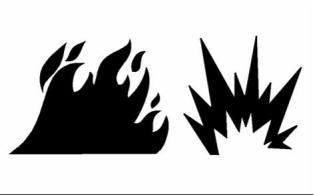
All fuels, most lubricants, and some coolant mixtures
are flammable.
Flammable fluids that are leaking or spilled onto hot
surfaces or onto electrical components can cause
a fire. Fire may cause personal injury and property
damage.
Contact with high pressure fuel may cause fluid
penetration and burn hazards. High pressure fu-
el spray may cause a fire hazard. Failure to fol-
low these inspection, maintenance and service in-
structions may cause personal injury or death.
After the emergency stop button is operated ensure
that you allow 15 minutes, before the engine covers
are removed.
Determine whether the engine will be operated in an
environment that allows combustible gases to be
drawn into the air inlet system. These gases could
cause the engine to overspeed. Personal injury,
property damage, or engine damage could result.
After the engine has stopped, you must wait for 10
minutes in order to allow the fuel pressure to be
purged from the high pressure fuel lines before any
service or repair is performed on the engine fuel lines.
If the application involves the presence of combustible
gases, consult your Perkins dealer and/or your
Perkins distributor for additional information about
suitable protection devices.
Ensure that the engine is stopped. Inspect all lines
and hoses for wear or for deterioration. The hoses
must be correctly routed. The lines and hoses must
have adequate support and secure clamps.
Remove all flammable combustible materials or
conductive materials such as fuel, oil, and debris from
the engine. Do not allow any flammable combustible
materials or conductive materials to accumulate on
the engine.
Oil filters and fuel filters must be correctly installed.
The filter housings must be tightened to the correct
torque. Refer to the Disassembly and Assembly
manual for more information.
This document is printed from SPI². Not for RESALE
![]()
![]()
![]()
![]()
SEBU8603-01
13
Safety Section
Fire Prevention and Explosion Prevention
Incorrect jumper cable connections can cause
an explosion that can result in injury. Refer to
the Operation Section of this manual for specific
instructions.
Do not charge a frozen battery. This may cause an
explosion.
The batteries must be kept clean. The covers
(if equipped) must be kept on the cells. Use the
recommended cables, connections, and battery box
covers when the engine is operated.
Fire Extinguisher
Make sure that a fire extinguisher is available. Be
familiar with the operation of the fire extinguisher.
Inspect the fire extinguisher and service the fire
extinguisher regularly. Obey the recommendations
on the instruction plate.
g00704059
Illustration 12
Lines, Tubes and Hoses
Use caution when you are refueling an engine. Do
not smoke while you are refueling an engine. Do not
refuel an engine near open flames or sparks. Always
stop the engine before refueling.
Do not bend high pressure lines. Do not strike high
pressure lines. Do not install any lines that are
damaged.
Leaks can cause fires. Consult your Perkins dealer
or your Perkins distributor for replacement parts.
Replace the parts if any of the following conditions
are present:
• High pressure fuel line or lines are removed.
• End fittings are damaged or leaking.
• Outer coverings are chafed or cut.
• Wires are exposed.
• Outer coverings are ballooning.
• Flexible part of the hoses are kinked.
• Outer covers have embedded armoring.
• End fittings are displaced.
g00704135
Illustration 13
Make sure that all clamps, guards, and heat shields
are installed correctly. During engine operation, this
will help to prevent vibration, rubbing against other
parts, and excessive heat.
Gases from a battery can explode. Keep any open
flames or sparks away from the top of a battery. Do
not smoke in battery charging areas.
Never check the battery charge by placing a metal
object across the terminal posts. Use a voltmeter or
a hydrometer.
This document is printed from SPI². Not for RESALE
![]()
![]()
![]()
14
SEBU8603-01
Safety Section
Crushing Prevention and Cutting Prevention
i02143194
Crushing Prevention and
Cutting Prevention
Support the component correctly when work beneath
the component is performed.
Unless other maintenance instructions are provided,
never attempt adjustments while the engine is
running.
Stay clear of all rotating parts and of all moving
parts. Leave the guards in place until maintenance
is performed. After the maintenance is performed,
reinstall the guards.
Keep objects away from moving fan blades. The fan
blades will throw objects or cut objects.
When objects are struck, wear protective glasses in
order to avoid injury to the eyes.
Chips or other debris may fly off objects when objects
are struck. Before objects are struck, ensure that no
one will be injured by flying debris.
i04016709
Mounting and Dismounting
Do not climb on the engine or the engine
aftertreatment. The engine and aftertreatment have
not been designed with mounting or dismounting
locations.
Refer to the OEM for the location of foot and hand
holds for your specific application.
i03550790
High Pressure Fuel Lines
Contact with high pressure fuel may cause fluid
penetration and burn hazards. High pressure fu-
el spray may cause a fire hazard. Failure to fol-
low these inspection, maintenance and service in-
structions may cause personal injury or death.
This document is printed from SPI². Not for RESALE
![]()
![]()
![]()
SEBU8603-01
15
Safety Section
High Pressure Fuel Lines
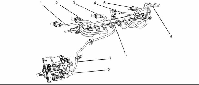
g01877473
Illustration 14
(1) High pressure line
(2) High pressure line
(3) High pressure line
(4) High pressure line
(5) High pressure line
(6) High pressure line
(7) High pressure fuel manifold (rail)
(8) High pressure line
(9) Fuel transfer line that is high pressure
The high pressure fuel lines are the fuel lines that
are between the high pressure fuel pump and the
high pressure fuel manifold and the fuel lines that are
between the fuel manifold and cylinder head. These
fuel lines are different from fuel lines on other fuel
systems.
Visually inspect the high pressure fuel lines before
the engine is started. This inspection should be each
day.
If you inspect the engine in operation, always use
the proper inspection procedure in order to avoid
a fluid penetration hazard. Refer to Operation and
Maintenance Manual, “General hazard Information”.
This is because of the following items:
• The high pressure fuel lines are constantly charged
with high pressure.
• Inspect the high pressure fuel lines for damage,
deformation, a nick, a cut, a crease, or a dent.
• The internal pressures of the high pressure fuel
lines are higher than other types of fuel system.
• Do not operate the engine with a fuel leak. If there
is a leak do not tighten the connection in order
to stop the leak. The connection must only be
tightened to the recommended torque. Refer to
Disassembly and Assembly, “Fuel injection lines -
Remove and Fuel injection lines - Install”.
• The high pressure fuel lines are formed to shape
and then strengthened by a special process.
Do not step on the high pressure fuel lines. Do not
deflect the high pressure fuel lines. Do not bend or
strike the high pressure fuel lines. Deformation or
damage of the high pressure fuel lines may cause a
point of weakness and potential failure.
• If the high pressure fuel lines are torqued correctly
and the high pressure fuel lines are leaking the
high pressure fuel lines must be replaced.
• Ensure that all clips on the high pressure fuel lines
are in place. Do not operate the engine with clips
that are damaged, missing or loose.
Do not check the high pressure fuel lines with the
engine or the starting motor in operation. After the
engine has stopped, you must wait for 10 minutes in
order to allow the fuel pressure to be purged from the
high pressure fuel lines before any service or repair
is performed on the engine fuel lines.
• Do not attach any other item to the high pressure
fuel lines.
• Loosened high pressure fuel lines must be
replaced. Also removed high pressure fuel lines
must be replaced. Refer to Disassembly and
assembly manual, “ Fuel Injection Lines - Install”.
Do not loosen the high pressure fuel lines in order
to remove air from the fuel system. This procedure
is not required.
This document is printed from SPI². Not for RESALE
![]()
![]()
16
SEBU8603-01
Safety Section
Before Starting Engine
i02813489
All protective guards and all protective covers must
be installed if the engine must be started in order
to perform service procedures. To help prevent an
accident that is caused by parts in rotation, work
around the parts carefully.
Before Starting Engine
Before the initial start-up of an engine that is new,
serviced or repaired, make provision to shut the
engine off, in order to stop an overspeed. This may
be accomplished by shutting off the air and/or fuel
supply to the engine.
Start the engine from the operators compartment or
from the engine start switch.
Always start the engine according to the procedure
that is described in the Operation and Maintenance
Manual, “Engine Starting” topic in the Operation
Section. Knowing that the correct procedure will help
to prevent major damage to the engine components.
Knowing that the procedure will also help to prevent
personal injury.
Overspeed shutdown should occur automatically for
engines that are controlled electronically. If automatic
shutdown does not occur, press the emerg, ency stop
button in order to cut the fuel and/or air to the engine.
Inspect the engine for potential hazards.
To ensure that the jacket water heater (if equipped)
and/or the lube oil heater (if equipped) is working
correctly, check the water temperature gauge. Also,
check the oil temperature gauge during the heater
operation.
Before starting the engine, ensure that no one is on,
underneath, or close to the engine. Ensure that the
area is free of personnel.
If equipped, ensure that the lighting system for the
engine is suitable for the conditions. Ensure that all
lights work correctly, if equipped.
Engine exhaust contains products of combustion
which can be harmful to your health. Always start the
engine and operate the engine in a well ventilated
area. If the engine is started in an enclosed area,
vent the engine exhaust to the outside.
All protective guards and all protective covers must
be installed if the engine must be started in order
to perform service procedures. To help prevent an
accident that is caused by parts in rotation, work
around the parts carefully.
Note: The engine is equipped with a device for cold
starting. If the engine will be operated in very cold
conditions, then an extra cold starting aid may be
required. Normally, the engine will be equipped with
the correct type of starting aid for your region of
operation.
Do not bypass the automatic shutoff circuits. Do not
disable the automatic shutoff circuits. The circuits are
provided in order to help prevent personal injury. The
circuits are also provided in order to help prevent
engine damage.
These engines are equipped with a glow plug starting
aid in each individual cylinder that heats the intake air
in order to improve starting. Some Perkins engines
may have a cold starting system that is controlled by
the ECM that allows a controlled flow of ether into
the engine. The ECM will disconnect the glow plugs
before the ether is introduced. This system would
be installed at the factory.
See the Service Manual for repairs and for
adjustments.
i03996487
Engine Starting
i02234873
Engine Stopping
Do not use aerosol types of starting aids such as
ether. Such use could result in an explosion and
personal injury.
Stop the engine according to the procedure in
the Operation and Maintenance Manual, “Engine
Stopping (Operation Section)” in order to avoid
overheating of the engine and accelerated wear of
the engine components.
If a warning tag is attached to the engine start switch,
or to the controls DO NOT start the engine or move
the controls. Consult with the person that attached
the warning tag before the engine is started.
This document is printed from SPI². Not for RESALE
![]()
![]()
![]()
SEBU8603-01
17
Safety Section
Electrical System
Grounding Practices
Use the Emergency Stop Button (if equipped) ONLY
in an emergency situation. Do not use the Emergency
Stop Button for normal engine stopping. After an
emergency stop, DO NOT start the engine until the
problem that caused the emergency stop has been
corrected.
Stop the engine if an overspeed condition occurs
during the initial start-up of a new engine or an engine
that has been overhauled.
To stop an electronically controlled engine, cut the
power to the engine and/or shutting off the air supply
to the engine.
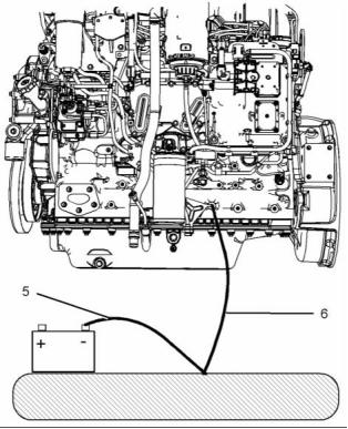
i04193189
Electrical System
Never disconnect any charging unit circuit or battery
circuit cable from the battery when the charging unit
is operating. A spark can cause the combustible
gases that are produced by some batteries to ignite.
To help prevent sparks from igniting combustible
gases that are produced by some batteries, the
negative “−” cable should be connected last from
the external power source to the primary position for
grounding.
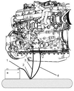
g02383098
Illustration 15
Typical example
(1) Ground to the battery
Check the electrical wires daily for wires that
are loose or frayed. Tighten all loose electrical
connections before the engine is started. Repair all
frayed electrical wires before the engine is started.
See the Operation and Maintenance Manual for
specific starting instructions.
(2) Primary position for grounding
(3) Ground to the starting motor
(4) Ground to the engine block
This document is printed from SPI². Not for RESALE
![]()
![]()
![]()
18
SEBU8603-01
Safety Section
Engine Electronics
The power supply connections and the ground
connections for the engine electronics should always
be from the isolator to the battery.
i03642610
Engine Electronics
Tampering with the electronic system installation
or the OEM wiring installation can be dangerous
and could result in personal injury or death and/or
engine damage.
Electrical Shock Hazard. The electronic unit injec-
tors use DC voltage. The ECM sends this voltage
to the electronic unit injectors. Do not come in
contact with the harness connector for the elec-
tronic unit injectors while the engine is operating.
Failure to follow this instruction could result in
personal injury or death.
g02383099
Illustration 16
Typical example
This engine has a comprehensive, programmable
Engine Monitoring System. The Electronic Control
Module (ECM) has the ability to monitor the engine
operating conditions. If any of the engine parameters
extend outside an allowable range, the ECM will
initiate an immediate action.
(5) Ground to the battery
(6) Ground to the cylinder block
Correct grounding for the engine electrical system
is necessary for optimum engine performance
and reliability. Incorrect grounding will result in
uncontrolled electrical circuit paths and in unreliable
electrical circuit paths.
The following actions are available for engine
monitoring control:
Uncontrolled electrical circuit paths can result in
damage to the crankshaft bearing journal surfaces
and to aluminum components.
• Warning
• Derate
Engines that are installed without engine-to-frame
ground straps can be damaged by electrical
discharge.
• Shutdown
The following monitored engine operating conditions
have the ability to limit engine speed and/or the
engine power:
To ensure that the engine and the engine electrical
systems function correctly, an engine-to-frame
ground strap with a direct path to the battery must be
used. This path may be provided by way of a direct
engine ground to the frame.
• Engine Coolant Temperature
• Engine Oil Pressure
The connections for the grounds should be tight and
free of corrosion. The engine alternator must be
grounded to the negative “-” battery terminal. The
grounding wire must be adequate to handle the full
charging current of the alternator.
• Engine Speed
• Intake Manifold Air Temperature
• Engine Intake Throttle Valve Fault
• Wastegate Regulator
This document is printed from SPI². Not for RESALE
![]()
![]()
![]()
![]()
![]()
![]()
SEBU8603-01
19
Safety Section
Engine Electronics
• Supply Voltage to Sensors
• Fuel Pressure in Manifold (Rail)
• NOx Reduction System
• Engine Aftertreatment System
The Engine Monitoring package can vary for different
engine models and different engine applications.
However, the monitoring system and the engine
monitoring control will be similar for all engines.
Note: Many of the engine control systems and display
modules that are available for Perkins Engines will
work in unison with the Engine Monitoring System.
Together, the two controls will provide the engine
monitoring function for the specific engine application.
Refer to Troubleshooting for more information on the
Engine Monitoring System.
This document is printed from SPI². Not for RESALE
![]()
20
SEBU8603-01
Product Information Section
Model Views
Product Information
Section
Model Views
i04171351
Model View Illustrations
The following model views show typical features
of the engine. Due to individual applications, your
engine may appear different from the illustrations.
Engine views
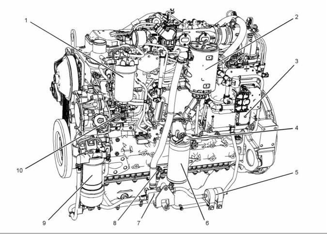
g02361696
Illustration 17
Typical example
(1) Secondary fuel filter
(2) Crankcase breather
(5) Fuel strainer
(6) Oil filter
(9) Primary fuel filter
(10) High-pressure fuel pump
(3) Electronic control module (ECM)
(4) Oil sampling valve
(7) Fuel priming pump
(8) Oil gauge (Dipstick)
This document is printed from SPI². Not for RESALE
![]()
![]()
![]()
SEBU8603-01
21
Product Information Section
Model Views
The location of the in-line strainer (5) and the priming
pump (7) will depend on the application.
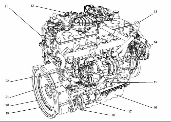
g02361697
Illustration 18
Typical example
(11) Rear lifting eye
(15) Back pressure valve
(19) Flywheel housing
(12) NOx reduction system (NRS)
(13) Front lifting eye
(14) Turbocharger
(16) Engine oil pan (Sump)
(17) Starting motor
(18) Engine oil drain plug
(20) Flywheel
(21) Exhaust outlet
(22) Exhaust gas cooler
This document is printed from SPI². Not for RESALE
![]()
![]()
22
SEBU8603-01
Product Information Section
Model Views
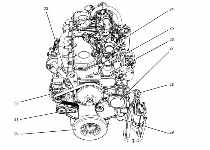
g02379457
Illustration 19
Typical example
(23) Belt
(27) Water pump
(32) Alternator
(24) Connection for air inlet
(25) Outlet connection for the coolant
(26) Water temperature regulator housing
(Thermostat housing)
(28) Oil filler
(29) Inlet connection for the Coolant
(30) Vibration damper
(31) Belt tensioner
This document is printed from SPI². Not for RESALE
![]()
![]()
SEBU8603-01
23
Product Information Section
Model Views
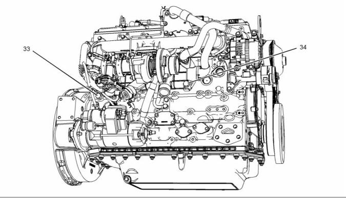
g02381218
Illustration 20
Typical example
(33) Coolant drain plug for cylinder block
(34) Coolant drain plug for exhaust gas
cooler
This document is printed from SPI². Not for RESALE
![]()
![]()
24
SEBU8603-01
Product Information Section
Model Views
Engine Aftertreatment System
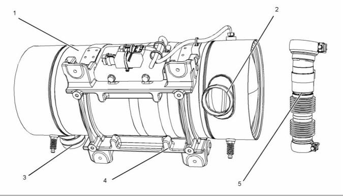
g02384560
Illustration 21
Typical example
(1) Clean emissions module (CEM)
(2) Inlet connection
(3) Outlet connection
(4) Mounting cradle
(5) Flexible exhaust pipe from engine to
CEM
i04340730
Engine Description
The Perkins 1206-E66 Industrial Engine has the
following characteristics.
• In-line Six cylinder
• Four stroke cycle
• Turbocharged charge cooled
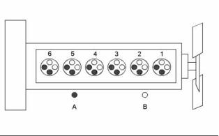
g01127295
Engine Specifications
Illustration 22
Cylinder and valve location
Note: The front end of the engine is opposite the
flywheel end of the engine. The left and the right
sides of the engine are determined from the flywheel
end. The number 1 cylinder is the front cylinder.
(A) Exhaust valves
(B) Inlet valves
This document is printed from SPI². Not for RESALE
![]()
![]()
![]()
SEBU8603-01
25
Product Information Section
Model Views
Table 1
Engine Diagnostics
Engine Specifications
The engine has built-in diagnostics in order to ensure
that the engine systems are functioning correctly. The
operator will be alerted to the condition by a “Stop or
Warning” lamp. Under certain conditions, the engine
horsepower and the vehicle speed may be limited.
The electronic service tool may be used to display
the diagnostic codes.
Operating Range (rpm)
Number of Cylinders
Bore
900 to 2800
(1)
6 In-Line
105 mm (4.13 inch)
127 mm (5 inch)
Stroke
Power
129.4 kW (173.52 hp)
There are three types of diagnostic codes: active,
logged, and event.
Aspiration
Turbocharged charge
cooled
Compression Ratio
Displacement
16.5:1
Most of the diagnostic codes are logged and stored
in the ECM. For additional information, refer to
the Operation and Maintenance Manual, “Engine
Diagnostics” topic (Operation Section).
6.6 L (402.7 cubic inch)
1-5-3-6-2-4
Firing Order
Rotation (flywheel end)
Counterclockwise
The ECM provides an electronic governor that
controls the injector output in order to maintain the
desired engine rpm.
(1) The operating rpm is dependent on the engine rating, the
application, and the configuration of the throttle.
Electronic Engine Features
Engine Cooling and Lubrication
The engine operating conditions are monitored.
The Electronic Control Module (ECM) controls the
response of the engine to these conditions and to
the demands of the operator. These conditions and
operator demands determine the precise control of
fuel injection by the ECM. The electronic engine
control system provides the following features:
The cooling system and lubrication system consists
of the following components:
• Gear-driven centrifugal water pump
• Water temperature regulator which regulates the
engine coolant temperature
• Engine monitoring
• Gear-driven rotor type oil pump
• Oil cooler
• Engine speed governing
• Control of the injection pressure
• Cold start strategy
The engine lubricating oil is supplied by a rotor type
oil pump. The engine lubricating oil is cooled and the
engine lubricating oil is filtered. The bypass valve
can provide unrestricted flow of lubrication oil to
the engine if the oil filter element should become
plugged.
• Automatic air/fuel ratio control
• Torque rise shaping
Engine efficiency, efficiency of emission controls, and
engine performance depend on adherence to proper
operation and maintenance recommendations.
Engine performance and efficiency also depend on
the use of recommended fuels, lubrication oils, and
coolants. Refer to this Operation and Maintenance
Manual, “Maintenance Interval Schedule” for more
information on maintenance items.
• Injection timing control
• System diagnostics
• Low temperature regeneration
For more information on electronic engine features,
refer to the Operation and Maintenance Manual,
“Features and Controls” topic (Operation Section).
Aftertreatment System
The aftertreatment system is approved for use by
Perkins. In order to be emission-compliant only the
approved Perkins aftertreatment system must be
used on a Perkins engine.
This document is printed from SPI². Not for RESALE
![]()

26
SEBU8603-01
Product Information Section
Model Views
Clean Emission Module (CEM)
The CEM comprises of two main components in a
single unit, the Diesel Oxidation Catalyst DOC and
the Diesel Particulate Filter DPF. The function of the
CEM is to ensure that the engine exhaust meets
the required emissions regulation for the country of
operation.
The engine exhaust is connected by a flexible pipe to
the CEM. The exhaust gases pass through the DOC
in order to remove contaminants, carbon monoxide,
and hydrocarbons. The exhaust gases then enter the
DPF where any particulate matter soot and ash will
be trapped.
The CEM uses a passive regeneration process to
ensure that normal operation of the engine removes
the soot. The soot is removed at an equal rate of
which the soot is captured. The ash remains in the
DPF and must be removed at an engine overhaul.
Engine Service Life
Engine efficiency and maximum utilization of engine
performance depend on the adherence to proper
operation and maintenance recommendations. In
addition, use recommended fuels, coolants, and
lubricants. Use the Operation and Maintenance
Manual as a guide for required engine maintenance.
Expected engine life is generally predicted by the
average power that is demanded. The average power
that is demanded is based on fuel consumption of
the engine over a period of time. Reduced hours of
operation at full throttle and/or operating at reduced
throttle settings result in a lower average power
demand. Reduced hours of operation will increase
the length of operating time before an engine
overhaul is required. For more information, refer to
the Operation and Maintenance Manual, “Overhaul
Considerations” topic (Maintenance Section).
Aftermarket Products and Perkins
Engines
Perkins does not warrant the quality or performance
of non-Perkins fluids and filters.
When auxiliary devices, accessories, or consumables
(filters, additives, catalysts,) which are made by other
manufacturers are used on Perkins products, the
Perkins warranty is not affected simply because of
such use.
However, failures that result from the installation
or use of other manufacturers devices,
accessories, or consumables are NOT Perkins
defects. Therefore, the defects are NOT covered
under the Perkins warranty.
This document is printed from SPI². Not for RESALE
![]()
SEBU8603-01
27
Product Information Section
Product Identification Information
Product Identification
Information
i03865704
Plate Locations and Film
Locations
(Engine Aftertreatment System
)
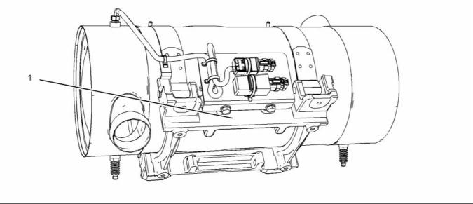
g02109488
Illustration 23
Typical example
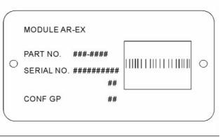
The module arrangement exhaust plate is installed
on the mounting plate (1). The location of the
arrangement plate mounting plate can alter
depending on the application.
Record the information that is on the plate. This
information identifies the engine aftertreatment
system. This information will be required by your
Perkins distributor. The information is essential in
order to be emissions complaint.
i03867276
Reference Numbers
Information for the following items may be needed to
order parts. Locate the information for your engine.
Record the information in the appropriate space.
Make a copy of this list for a record. Keep the
information for future reference.
Record for Reference
g02109493
Illustration 24
Module Arrangement Exhaust Plate
Engine Model _______________________________________________
This document is printed from SPI². Not for RESALE
![]()
![]()
![]()
28
SEBU8603-01
Product Information Section
Product Identification Information
Engine Serial number _____________________________________
Engine Low Idle rpm ______________________________________
Engine Full Load rpm _____________________________________
Primary Fuel Filter _________________________________________
Water Separator Element ________________________________
Secondary Fuel Filter Element __________________________
Lubrication Oil Filter Element ___________________________
Auxiliary Oil Filter Element _______________________________
Total Lubrication System Capacity _____________________
Total Cooling System Capacity _________________________
Air Cleaner Element _______________________________________
Drive Belt ____________________________________________________
Engine Aftertreatment System
Part Number ________________________________________________
Serial Number ______________________________________________
i04274850
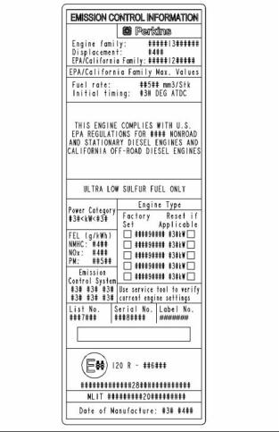
Emissions Certification Film
g02443596
Illustration 25
Typical example
An emission label is installed on the front gear cover.
Note: A second emission label will be supplied with
the engine. If necessary, the second emission label
will be installed on the application by the original
equipment manufacturer.
This document is printed from SPI². Not for RESALE
![]()
![]()
免费热线
400-100-8969 15088860848
400-100-8969 15088860848
机组销售
0574-26871589 15267810868
0574-26871589 15267810868
配件销售
0574-26886646 15706865167
0574-26886646 15706865167
维修热线
0574-26871569 18658287286
0574-26871569 18658287286
手机端

微信公众号