 English
 Espaol
 Franais
 阿拉伯
阿拉伯 中文(简)
中文(简) Deutsch
 Italiano
 Português
 日本
日本 韩国
韩国 български
 hrvatski
 esky
esky Dansk
Dansk Nederlands
 suomi
suomi Ελληνικ
 印度
印度 norsk
norsk Polski
 Roman
Roman русский
 Svenska
 珀金斯Perkins1306WK-WS用户手册,珀金斯Perkins1306WK-WS用户手册技术支持中心,珀金斯Perkins1306WK-WS用户手册代理商,珀金斯Perkins1306WK-WS用户手册销售服务中心,珀金斯Perkins1306WK-WS用户手册价格规格资料查询,宁波日昕动力科技有限公司

珀金斯Perkins1306WK-WS用户手册
详细描述
Perkins 1300 Series EDi
Models WK to WS
USER’S HANDBOOK
Six cylinder, turbocharged, diesel engines with an
electronic management system for industrial and
agricultural applications
Publication TPD 1352E, Issue 4.
© Proprietary information of Perkins Engines Company Limited, all rights reserved.
The information is correct at the time of print.
Published in November 2011 by Technical Publications,
Perkins Engines Company Limited, Peterborough PE1 5NA, England
i
This document is printed from SPI². Not for RESALE
![]()
![]()
Thispublication iswritten in
PerkinsApproved ClearEnglish
This publication is divided into six chapters:
1 General information
2 Engine views
3 Operation instructions
4 Preventive maintenance
5 Engine fluids
6 Fault diagnosis
The following pages contain a detailed table of contents
ii
This document is printed from SPI². Not for RESALE
![]()
![]()

1300 Series EDi Models WK to WS
Contents
1 General information
Introduction . ... ... ... ... ... ... ... ... ... ... ... ... ... ... ... ... ... ... ... ... ... ... ... ... ... ... ... ... ... .. 1
Safety precautions .. ... ... ... ... ... ... ... ... ... ... ... ... ... ... ... ... ... ... ... ... ... ... ... ... ... ... .. 2
How to care for your engine ... ... ... ... ... ... ... ... ... ... ... ... ... ... ... ... ... ... ... ... ... ... ... .. 3
Engine preservation ... ... ... ... ... ... ... ... ... ... ... ... ... ... ... ... ... ... ... ... ... ... ... ... ... ... .. 4
Parts and service ... ... ... ... ... ... ... ... ... ... ... ... ... ... ... ... ... ... ... ... ... ... ... ... ... ... ... .. 5
Training ... ... ... ... ... ... ... ... ... ... ... ... ... ... ... ... ... ... ... ... ... ... ... ... ... ... ... ... ... ... ... .. 5
Service literature . ... ... ... ... ... ... ... ... ... ... ... ... ... ... ... ... ... ... ... ... ... ... ... ... ... ... ... .. 5
Engine identification ... ... ... ... ... ... ... ... ... ... ... ... ... ... ... ... ... ... ... ... ... ... ... ... ... ... .. 6
Engine data . ... ... ... ... ... ... ... ... ... ... ... ... ... ... ... ... ... ... ... ... ... ... ... ... ... ... ... ... ... .. 8
2 Engine views
Introduction . ... ... ... ... ... ... ... ... ... ... ... ... ... ... ... ... ... ... ... ... ... ... ... ... ... ... ... ... ... 11
Location of engine parts .. ... ... ... ... ... ... ... ... ... ... ... ... ... ... ... ... ... ... ... ... ... ... ... ... 11
3 Operation instructions
How to start the engine ... ... ... ... ... ... ... ... ... ... ... ... ... ... ... ... ... ... ... ... ... ... ... ... ... 13
How to start an engine with an ether start system .. ... ... ... ... ... ... ... ... ... ... ... ... ... ... 15
How to stop the engine ... ... ... ... ... ... ... ... ... ... ... ... ... ... ... ... ... ... ... ... ... ... ... ... ... 16
Adjustment of engine speed range . ... ... ... ... ... ... ... ... ... ... ... ... ... ... ... ... ... ... ... ... 16
Engine operation at idle speed ... ... ... ... ... ... ... ... ... ... ... ... ... ... ... ... ... ... ... ... ... ... 16
Running-in ... ... ... ... ... ... ... ... ... ... ... ... ... ... ... ... ... ... ... ... ... ... ... ... ... ... ... ... ... ... 16
Altitude ... ... ... ... ... ... ... ... ... ... ... ... ... ... ... ... ... ... ... ... ... ... ... ... ... ... ... ... ... ... ... 16
User’s Handbook, TPD 1352E, issue 3
iii
This document is printed from SPI². Not for RESALE
![]()
![]()
1300 Series EDi Models WK to WS
4 Preventive maintenance
Preventive maintenance periods . ... ... ... ... ... ... ... ... ... ... ... ... ... ... ... ... ... ... ... ... ... 17
Schedules ... ... ... ... ... ... ... ... ... ... ... ... ... ... ... ... ... ... ... ... ... ... ... ... ... ... ... ... ... ... 18
How to drain the cooling system .. ... ... ... ... ... ... ... ... ... ... ... ... ... ... ... ... ... ... ... ... ... 19
How to fill the cooling system .. ... ... ... ... ... ... ... ... ... ... ... ... ... ... ... ... ... ... ... ... ... ... 20
How to renew the canister of the coolant filter / inhibitor . ... ... ... ... ... ... ... ... ... ... ... ... 21
How to check the drive belt . ... ... ... ... ... ... ... ... ... ... ... ... ... ... ... ... ... ... ... ... ... ... ... 22
How to remove the drive belt ... ... ... ... ... ... ... ... ... ... ... ... ... ... ... ... ... ... ... ... ... ... ... 22
Fuel pre-filter ... ... ... ... ... ... ... ... ... ... ... ... ... ... ... ... ... ... ... ... ... ... ... ... ... ... ... ... ... 23
How to renew the fuel strainer and the canister of the fuel filter .. ... ... ... ... ... ... ... ... ... 23
How to eliminate air from the fuel system ... ... ... ... ... ... ... ... ... ... ... ... ... ... ... ... ... ... 24
How to renew the lubricating oil ... ... ... ... ... ... ... ... ... ... ... ... ... ... ... ... ... ... ... ... ... ... 25
How to renew the canister of the lubricating oil filter ... ... ... ... ... ... ... ... ... ... ... ... ... ... 26
Air filter ... ... ... ... ... ... ... ... ... ... ... ... ... ... ... ... ... ... ... ... ... ... ... ... ... ... ... ... ... ... ... 27
Restriction indicator . ... ... ... ... ... ... ... ... ... ... ... ... ... ... ... ... ... ... ... ... ... ... ... ... ... ... 27
How to set the valve tip clearances . ... ... ... ... ... ... ... ... ... ... ... ... ... ... ... ... ... ... ... ... 28
5 Engine fluids
Fuel specification . ... ... ... ... ... ... ... ... ... ... ... ... ... ... ... ... ... ... ... ... ... ... ... ... ... ... ... 29
Lubricating oil specification .. ... ... ... ... ... ... ... ... ... ... ... ... ... ... ... ... ... ... ... ... ... ... ... 30
Coolant specification ... ... ... ... ... ... ... ... ... ... ... ... ... ... ... ... ... ... ... ... ... ... ... ... ... ... 31
6 Fault diagnosis
Problems and possible causes ... ... ... ... ... ... ... ... ... ... ... ... ... ... ... ... ... ... ... ... ... ... 33
List of possible causes ... ... ... ... ... ... ... ... ... ... ... ... ... ... ... ... ... ... ... ... ... ... ... ... ... 34
iv
User’s Handbook, TPD 1352E, issue 3
This document is printed from SPI². Not for RESALE
![]()
![]()
1300 Series EDi Models WK to WS
1
General information
1
Introduction
The 1300 Series EDi is a family of engines which have an electronic management system. The engines are
designed for industrial and agricultural applications from Perkins Engines Limited, a world leader in the design
and manufacture of high-performance diesel engines.
Perkins approved assembly and quality standards, together with the latest technology, have been applied to
the manufacture of your engine to give you reliable and economic power.
Note: To ensure that you use the relevant information for your specific engine type, refer to "Engine
identification" on page 6.
Danger is indicated in the text by two methods:
Warning! This indicates that there is a possible danger to the person.
Caution: This indicates that there is a possible danger to the engine.
Note: Is used where the information is important, but there is not a danger.
A
W251/1
User’s Handbook, TPD 1352E, issue 4
1
This document is printed from SPI². Not for RESALE
![]()
![]()
1
1300 Series EDi Models WK to WS
Safety precautions
These safety precautions are important.
You must refer also to the local regulations in the country of use. Some items only apply to specific
applications.
z Only use these engines in the type of application for which they have been designed.
z Do not change the specification of the engine.
z Do not smoke when you put fuel in the tank.
z Clean away fuel which has been spilt. Material which has been contaminated by fuel must be moved to a
safe place.
z Do not put fuel in the tank while the engine runs (unless it is absolutely necessary).
z Do not clean, add lubricating oil, or adjust the engine while it runs (unless you have had the correct training;
even then extreme caution must be used to prevent injury).
z Do not make adjustments that you do not understand.
z Ensure that the engine does not run in a location where it can cause a concentration of toxic emissions.
z Other persons must be kept at a safe distance while the engine or auxiliary equipment is in operation.
z Do not permit loose clothing or long hair near moving parts.
z Keep away from moving parts during engine operation.
Warning! Some moving parts cannot be seen clearly while the engine runs.
z Do not operate the engine if a safety guard has been removed.
z Do not remove the filler cap or any component of the cooling system while the engine is hot and while the
coolant is under pressure, because dangerous hot coolant can be discharged.
z Do not use salt water or any other coolant which can cause corrosion in the closed coolant circuit.
z Do not allow sparks or fire near the batteries (especially when the batteries are on charge) because the
gases from the electrolyte are highly flammable. The battery fluid is dangerous to the skin and especially
to the eyes.
z Disconnect the battery terminals before a repair is made to the electrical system.
z Only one person must control the engine.
z Ensure that the engine is operated only from the control panel or from the operator's position. Discard used
lubricating oil in a safe place to prevent contamination.
z Ensure that the control lever of the transmission drive is in the "out-of-drive" position before the engine is
started.
z The combustible material of some components of the engine (for example certain seals) can become
extremely dangerous if it is burned. Never allow this burnt material to come into contact with the skin or with
the eyes.
z Diesel fuel and lubricating oil (especially used lubricating oil) can damage the skin of certain persons.
Protect your hands with gloves or a special solution to protect the skin.
z Do not wear clothing which is contaminated by lubricating oil. Do not put material which is contaminated
with oil into the pockets of clothing.
z Discard used lubricating oil in accordance with local regulations to prevent contamination.
z Use extreme care if emergency repairs must be made in adverse conditions.
Continued
2
User’s Handbook, TPD 1352E, issue 4
This document is printed from SPI². Not for RESALE
![]()
![]()
1
1300 Series EDi Models WK to WS
z Always use a safety cage to protect the operator when a component is to be pressure tested in a container
of water. Fit safety wires to secure the plugs which seal the hose connections of a component which is to
be pressure tested.
z Do not allow compressed air to contact your skin. If compressed air enters your skin, obtain medical help
immediately.
z Turbochargers operate at high speed and at high temperatures. Keep fingers, tools and debris away from
the inlet and outlet ports of the turbocharger and prevent contact with hot surfaces.
z The fuel injector units of this engine are controlled electronically by a pulse of 110 volts.
z The fuel injector units are actuated by high-pressure engine lubricating oil. Do not remove any component
of the high-pressure system while the engine oil is under pressure, because dangerous oil can be
discharged.
z Fit only genuine Perkins parts.
How to care for your engine
This handbook has been written to assist you to maintain and operate your engine correctly.
To obtain the best performance and the longest life from your engine, you must ensure that the maintenance
operations are done at the intervals indicated in Chapter 4, Preventive maintenance. If the engine works in a
very dusty environment or other adverse conditions, certain maintenance intervals will have to be reduced.
Renew the filter canisters and lubricating oil regularly in order to ensure that the inside of your engine remains
clean.
Ensure that all adjustments and repairs are done by personnel who have had the correct training. Perkins
distributors have this type of personnel available. You can also obtain parts and service from your Perkins
distributor.
The terms "left side" and "right side" apply when the engine is seen from the flywheel end.
Warning! Read the "Safety precautions" on page 2 and remember them. They are given for your protection
and must be applied at all times.
User’s Handbook, TPD 1352E, issue 4
3
This document is printed from SPI². Not for RESALE
![]()
![]()
1
1300 Series EDi Models WK to WS
Engine preservation
Introduction
The recommendations indicated below are designed to prevent damage to the engine when it is withdrawn
from service for a prolonged period. Use these procedures after the engine is withdrawn from service.
Procedure
Caution: The procedure for this engine is different to the procedure for other Perkins engines, because of the
design of the fuel injection units.
1 Completely clean the outside of the engine.
2 Operate the engine until it is warm. Stop the engine and drain the lubricating oil from the sump. Ensure that
the oil gallery of the high-pressure lubrication system is drained.
Caution: If the gallery is not drained, the engine cylinders will be filled with engine lubricating oil when the fuel
injector units are removed.
3 Drain the fuel supply gallery, fitted to the cylinder head.
Caution: If the gallery is not drained, the engine cylinders will be filled with fuel when the fuel injector units are
removed.
4 Renew the canister of the lubricating oil filter, see "How to renew the canister of the lubricating oil filter" on
page 26.
5 Fill the sump to the full mark on the dipstick with new and clean lubricating oil. Use a correct preservative
fluid instead of the lubricating oil. If a preservative fluid is used, this must be drained and the lubricating oil
sump must be filled to the correct level with normal lubricating oil at the end of the storage period.
6 Drain the coolant circuit, see "How to drain the cooling system" on page 19. In order to protect the cooling
system against corrosion, fill it with an approved antifreeze mixture because this gives protection against
corrosion.
Caution: If protection against frost is not necessary and a corrosion inhibitor is to be used, it is recommended
that you consult the Technical Service Department, Perkins Engines Company Limited, Peterborough.
7 Connect the battery, eliminate air from the fuel system. Operate the engine for a short period in order to
circulate the lubricating oil and the coolant in the engine. Then correct leakages of fuel, lubricating oil or air.
8 Disconnect the battery. Then put the battery into safe storage in a fully charged condition. Before the battery
is put into storage, protect its terminals against corrosion.
9 Remove the air filter. Then, if necessary, remove the pipe(s) installed between the air filter and the
turbocharger. Seal the air inlet to the turbocharger with waterproof tape.
Continued
4
User’s Handbook, TPD 1352E, issue 4
This document is printed from SPI². Not for RESALE
![]()
![]()
1
1300 Series EDi Models WK to WS
10 Remove the exhaust pipe. Seal the manifold or the turbocharger with waterproof tape.
11 Clean the engine breather pipe and seal the end of the pipe.
12 When a preservative fuel is to be used, drain the fuel system and fill it with the preservative fuel. If
preservative fuel is not used, the system can be completely filled with normal fuel but the fuel must be drained
and discarded at the end of the storage period together with the fuel filter canister.
13 Remove the drive belts and put them into storage.
14 Seal the vent pipe of the fuel tank or the fuel filler cap with waterproof tape.
Every month, the crankshaft must be rotated in order to change the spring loading on the valve train. Rotate
the crankshaft more than 180 degrees. Visibly check for damage or corrosion to the engine.
If the engine protection is done correctly according to the above recommendations, no corrosion damage will
normally occur. Perkins are not responsible for damage which may occur when an engine is in storage after a
period in service.
Parts and service
If problems occur with your engine or with the components fitted onto it, your Perkins distributor can make the
necessary repairs and will ensure that only the correct parts are fitted and that the work is done correctly.
Training
Local training for the correct operation, service and overhaul of engines is available at certain Perkins
distributors. If special training is necessary, your Perkins distributor can advise you how to obtain it at the
Perkins Customer Training Department, Peterborough, or other main centres.
Service literature
Workshop manuals, installation drawings and other service publications are available from your Perkins
distributor at a nominal cost.
User’s Handbook, TPD 1352E, issue 4
5
This document is printed from SPI². Not for RESALE
![]()
![]()
1
1300 Series EDi Models WK to WS
Engine identification
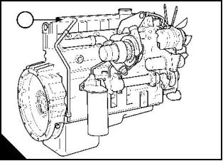
The 1300 Series EDi engines consist of a range of six cylinder in-line engines which are turbocharged or
turbocharged/intercooled. The engines have an electronic management system.
In this handbook, the different engine types are indicated by their code letters, which are the first two letters of
the engine number as indicated in table 1.
Table 1
Capacity
Code letters
Aspiration system
Litre
7,6
7,6
8,6
8,6
7,6
7,6
8,6
8,6
in3
466
466
531
531
466
466
531
531
WK
WL
Turbocharged
Turbocharged / intercooled
Turbocharged
WM
WN
WP
WQ
WR
WS
Turbocharged / intercooled
Turbocharged
Turbocharged / intercooled
Turbocharged
Turbocharged / intercooled
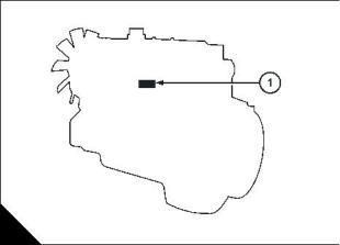
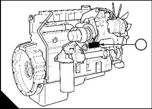
The engine number is stamped on the left side of the cylinder block (A1) on the earliest engines, behind the
high pressure pump. On later engines, the engine number is located at position (B1). On the current engine,
the identification plate is located on the top cover of the engine (C1).
An example of an engine number is WP1296N1234567.
The components of the engine number are as follows:
WP = Type code letters
1296 = Build list number
N = Built in the USA
1234567 = Engine serial number
Certain engines built after 4th January 2010 use a different engine number format. An example of the engine
number in the different engine format is WGBF1296N12345U.
The components of the engine number are as follows:
W = Engine series
G = Application
B = Engine type
F = Number of cylinders
1296 = Build list number
N = Built in the USA
123456U = Engine serial number
If you need parts, service or information for your engine, you must give the complete engine number to your
Perkins distributor.
6
User’s Handbook, TPD 1352E, issue 4
This document is printed from SPI². Not for RESALE
![]()
![]()

1
1300 Series EDi Models WK to WS
1
A
B
W002
PW250/1
1
C
User’s Handbook, TPD 1352E, issue 4
7
This document is printed from SPI². Not for RESALE
![]()
![]()
1
1300 Series EDi Models WK to WS
Engine data
Number of cylinders... ... ... ... ... ... ... ... ... ... ... ... ... ... ... ... ... ... ... ... ... ... ... ... ... ... ... ... ... ... ... ... ... ... ..6
Cylinder arrangement ... ... ... ... ... ... ... ... ... ... ... ... ... ... ... ... ... ... ... ... ... ... ... ... ... ... ... ... ... ... ... .. In line
Cycle.. ... ... ... ... ... ... ... ... ... ... ... ... ... ... ... ... ... ... ... ... ... ... ... ... ... ... ... ... ... ... ... ... ... ... ... ..Four stroke
Induction system ... ... ... ... ... ... ... ... ... ... ... ... ... ... ... ... ... ... ... Turbocharged or Turbocharged/intercooled
Combustion system ... ... ... ... ... ... ... ... ... ... ... ... ... ... ... ... ... ... ... ... ... ... ... ... ... ... ... ... ... Direct injection
Nominal bore:
- WK and WL.. ... ... ... ... ... ... ... ... ... ... ... ... ... ... ... ... ... ... ... ... ... ... ... ... ... ... ... ... ... 109,2 mm (4.301 in)
- WM, WN, WP, WQ, WR and WS. ... ... ... ... ... ... ... ... ... ... ... ... ... ... ... ... ... ... ... ... ... 116,6 mm (4.590 in)
Stroke:
- WK, WL , WP and WQ ... ... ... ... ... ... ... ... ... ... ... ... ... ... ... ... ... ... ... ... ... ... ... ... ... 118,9 mm (4.681 in)
- WM, WN, WR and WS. ... ... ... ... ... ... ... ... ... ... ... ... ... ... ... ... ... ... ... ... ... ... ... ... ... 135,9 mm (5.350 in)
Compression ratio.. ... ... ... ... ... ... ... ... ... ... ... ... ... ... ... ... ... ... ... ... ... ... ... ... ... ... ... ... ... ... ... ... ..16.5:1
Cubic capacity:
- WK, WL , WP and WQ. ... ... ... ... ... ... ... ... ... ... ... ... ... ... ... ... ... ... ... ... ... ... ... ... .. 7,64 litres (466.4 in3)
- WM, WN, WR and WS. ... ... ... ... ... ... ... ... ... ... ... ... ... ... ... ... ... ... ... ... ... ... ... ... .. 8,71 litres (531.0 in3)
Firing order. ... ... ... ... ... ... ... ... ... ... ... ... ... ... ... ... ... ... ... ... ... ... ... ... ... ... ... ... ... ... ... ... ..1, 5, 3, 6, 2, 4
Valve tip clearances (cold):
- Inlet and exhaust . ... ... ... ... ... ... ... ... ... ... ... ... ... ... ... ... ... ... ... ... ... ... ... ... ... ... ... ..0,64 mm (0.025 in)
Lubricating oil pressure (minimum):
- Idle... ... ... ... ... ... ... ... ... ... ... ... ... ... ... ... ... ... ... ... ... ... ... ... ... ... ... ... ..137 kPa (20 lbf in ) 1,4 kgf/cm2
2
2
- maximum engine speed and normal engine temperature ... ... ... ... ... ... ... ..276 kPa (40 lbf/in ) 2,8 kgf/cm2
Capacity of a typical lubricating oil sump (1)
:
- Without filter canister ... ... ... ... ... ... ... ... ... ... ... ... ... ... ... ... ... ... . 22,7 litres (40.0 UK pints) 24 US quarts
- With filter canister ... ... ... ... ... ... ... ... ... ... ... ... ... ... ... ... ... ... ... . 28,3 litres (49.9 UK pints) 28 US quarts
Typical coolant capacity (engine only)... ... ... ... ... ... ... ... ... ... ... .. 12,8 litres (22.5 UK pints) 13,5 US quarts
Direction of rotation ... ... ... ... ... ... ... ... ... ... ... ... ... ... ... ... ... ... ... ... ... ... ... ... ... . Clockwise from the front
(1) The capacity of the sump may vary according to the application. Fill to the "Full" mark on the dipstick. Do not exceed the "Full" mark.
8
User’s Handbook, TPD 1352E, issue 4
This document is printed from SPI². Not for RESALE
![]()
![]()
1
1300 Series EDi Models WK to WS
User’s Handbook, TPD 1352E, issue 4
9
This document is printed from SPI². Not for RESALE
![]()
![]()
This page is intentionally blank
This document is printed from SPI². Not for RESALE
1300 Series EDi Models WK to WS
2
Engine views
2
Introduction
Perkins engines are built for specific applications and the views which follow do not necessarily match your
engine specification.
Location of engine parts
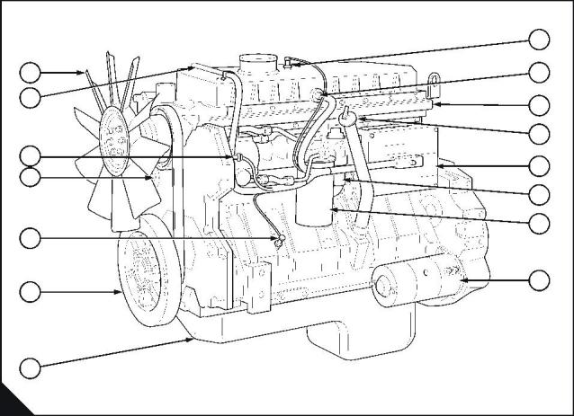
Front and left side view
1 Fan
8 Sensor for the inlet manifold air temperature
2 Wiring harness to the sensor for injection control 9 electrical connector for the injector units
pressure
10 Supply manifold
3 Sensor for engine oil temperature
11 Lubricating oil filler and dipstick
4 Camshaft position sensor
12 Engine control module
5 Sensor for engine oil pressure
13 Fuel strainer
6 Crankshaft damper
14 Canister for the fuel filter
7 Sump for the engine lubricating oil
15 Starter motor
8
9
1
2
10
11
3
4
12
13
14
5
6
15
7
A
PW251/2
User’s Handbook, TPD 1352E, issue 4
11
This document is printed from SPI². Not for RESALE
![]()
![]()
2
1300 Series EDi Models WK to WS
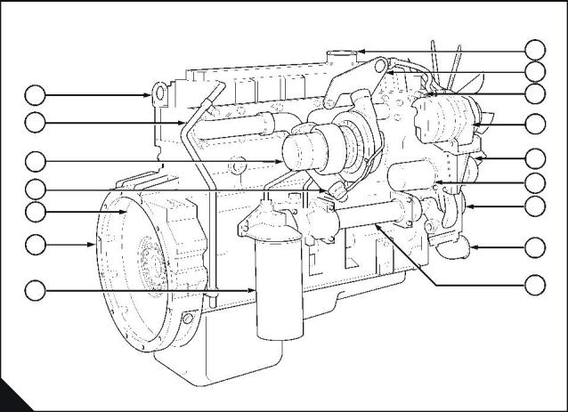
Rear and right side view
16 Rear lift bracket
17 Engine breather pipe
18 Turbocharger
24 Front lift bracket
25 Coolant temperature sensor
26 Alternator
19 Wastegate
27 Tensioner for the drive belt
28 Canister for the coolant filter / inhibitor
29 Coolant pump
20 Flywheel
21 Flywheel housing
22 Canister for the lubricating oil filter
23 Air inlet connection
30 Coolant inlet connection
31 Lubricating oil cooler
23
24
25
16
17
26
27
18
28
29
19
20
21
22
30
31
A
PW250
12
User’s Handbook, TPD 1352E, issue 4
This document is printed from SPI². Not for RESALE
![]()
![]()
1300 Series EDi Models WK to WS
3
Operation instructions
3
How to start the engine
Temperature of 15°C (60°F) to -10°C (14°F)
Several factors affect engine start, for example:
z The power of the batteries
z The performance of the starter motor
z The viscosity of the lubricating oil
z The installation of a cold start system.
The engine will start without a cold starting aid at temperatures as low as -10 °C (14 °F). In conditions where
the temperature is lower than this, a block heater or an ether start system may be necessary.
Before the engine is started the operator should understand fully the reason for the controls and their use.
Before the engine is started:
z Check that there is sufficient coolant and, if necessary, add the correct coolant, see Chapter 4, Preventive
maintenance.
z Check that there is sufficient lubricating oil in the sump and, if necessary, add lubricating oil. Refer to
Chapter 4, Preventive maintenance. Ensure that the lubricating oil is of the correct grade for the ambient
conditions.
z Fill the fuel tank with fuel of the correct specification, see Chapter 5, Engine fluids.
z Check the air filter and its connections.
z Ensure that all of the electrical connections are tight.
Notes:
z For the correct engine fluids, see Chapter 5, Engine fluids.
z The procedures to start the engine may vary according to the application. If possible, consult the User's
Handbook for the application.
1 Apply the hand brake, if the application is fitted with one. Ensure that the transmission is in the out-of-drive
position. Ensure that the engine speed control is in the minimum speed position.
2 Turn the start key to the "ON" position.
Note: Do not operate the engine speed control during engine start, the management system controls the
supply of fuel, and it will ignore signals from the speed control until the engine starts.
3 Turn the start key further to engage the starter motor. If the application has a start button, press and hold
the button.
4 Release the start key (or the button) as soon as the engine starts. The start key will return to the "ON"
position.
Caution: If the engine does not start within 30 seconds, release the start key and wait two to three minutes to
allow the starter motor to cool. If after three tries the engine does not start, turn the key to the "OFF" position.
Continued
User’s Handbook, TPD 1352E, issue 4
13
This document is printed from SPI². Not for RESALE
![]()
![]()
![]()
3
1300 Series EDi Models WK to WS
5 Locate and correct the problem. Always ensure that the engine and starter motor are stationary before the
starter motor is engaged again.
2
2
When the engine starts, check that the lubricating oil pressure exceeds 138 kPa (20 lbs/in ) 1,4 kgf/cm within
the first 10 seconds, see "Engine data" on page 8 for the correct lubricating oil pressure.
If a gauge is not fitted, check that the warning light for low oil pressure is extinguished. If this does not occur,
stop the engine and find and correct the fault. Allow the engine to warm at approximately 1000 rev/min for three
to five minutes before load is applied.
14
User’s Handbook, TPD 1352E, issue 4
This document is printed from SPI². Not for RESALE
![]()
![]()
3
1300 Series EDi Models WK to WS
How to start an engine with an ether start system
Ambient temperature below -20°C (-4°F)
Caution: Ether is very flammable and is toxic. Apply the safety precautions on the container for the use and
storage of ether and for the disposal of empty containers.
1 Apply the hand brake. Ensure that the transmission is in the out-of-drive position. Check the ether container
to ensure that a supply of ether is available under pressure.
2 Ensure that the engine speed control is still in the idle position.
Note: Do not operate the engine speed control during engine start, the management system controls fuel
supply and it will ignore signals from the speed control until the engine starts.
3 Turn the start key to the "ON" position.
4 Turn the start key further to engage the starter motor. If the application has a start button, press and hold
the button to engage the starter motor, and at the same time press the ether injection button. Allow one to two
seconds for the ether injection system to fill then release the injection button to release a measured amount of
ether into the engine.
Caution: Release of ether into the cylinders before the starter motor is engaged may cause damage to the
pistons and piston rings.
5 Release the start key (or the start button, if one is fitted) as soon as the engine starts. The start key will return
to the "ON" position.
Caution: If the engine does not start within 30 seconds, release the start key and wait two to three minutes to
allow the starter motor to cool. If after three tries the engine does not start, turn the key to the "OFF" position
and locate and correct the problem. Always ensure that the engine and starter motor are stationary before the
starter motor is engaged again.
Note: In extemely cold conditions, it is permissible to inject further ether into the engine if the engine runs
roughly after the initial start.
Caution: Do not inject ether into a warm engine.
6 When the engine starts check that the lubricating oil pressure exceeds 138 kPa (20 lbs/in ) 1,4 kgf/cm2
within the first 25 seconds, see "Engine data" on page 8 for the correct lubricating oil pressure. If a gauge is
not fitted, check that the warning light for low oil pressure is extinguished. If this does not occur, stop the
engine.
2
Find and correct the fault. Allow the engine to warm at approximately 1000 rev/min for three to five minutes
before load is applied.
User’s Handbook, TPD 1352E, issue 4
15
This document is printed from SPI². Not for RESALE
![]()
![]()
3
1300 Series EDi Models WK to WS
How to stop the engine
Turn the engine start key to the "OFF" position.
It is recommended that the engine is operated at idle speed for three to five minutes before the engine is
stopped. This will allow the lubricating oil and the coolant to carry the heat away from large ferrous
components.
Adjustment of engine speed range
The idle or maximum speed settings cannot be changed by the engine operator.
Engine operation at idle speed
Do not operate the engine for long periods at idle speed as this could have an adverse affect on the engine
performance or damage the engine.
Running-in
A gradual running-in of a new engine is not necessary. Prolonged operation at light loads during the early life
of the engine is not recommended.
Maximum load can be applied to a new engine as soon as the engine is put into service and the coolant
temperature has reached a minimum of 76 °C (170 °F).
z Do not operate the engine at high speeds without a load.
z Do not overload the engine.
Altitude
The engine management system will automatically compensate for altitude.
16
User’s Handbook, TPD 1352E, issue 4
This document is printed from SPI². Not for RESALE
![]()
![]()
1300 Series EDi Models WK to WS
4
Preventive maintenance
4
Preventive maintenance periods
These preventive maintenance periods apply to average conditions of operation. Check the periods given by
the manufacturer of the equipment in which the engine is installed. Use the periods which are shortest . When
the operation of the engine must conform to the local regulations these periods and procedures may need to
be adapted to ensure correct operation of the engine.
It is good preventive maintenance to check for leakage and loose fasteners at each service.
These maintenance periods apply only to engines that are operated with fuel and lubricating oil which conform
to the specifications given in this handbook.
User’s Handbook, TPD 1352E, issue 4
17
This document is printed from SPI². Not for RESALE
![]()
![]()
4
1300 Series EDi Models WK to WS
Schedules
The schedules which follow must be applied at the interval (hours or months) which occur first.
A
B
C
D
Every day or every 8 hours
Every 450 hours or 6 months
Every 900 hours or 12 months
Every 3600 hours or 24 months
E
F
Every 5000 hours
Every 6700 to 7500 hours
Annually
G
A
B
C
D
E
F
G
Operation
z
z
Ensure that the coolant is at the correct level
Check the intercooler and the coolant radiator for debris
z
z
z
Check, and adjust if necessary, the antifreeze mixture (2)
Test the level of coolant conditioner, and adjust if necessary (2)
Check the condition of the drive belt
z
Renew the coolant (4)
z
z
Renew the canister of the coolant filter (3)
Inspect the thermostat (2)
z
Drain water from the fuel pre-filter (1)
z
Renew the canister of the fuel filter and renew the fuel strainer
z
Ensure that the atomisers are checked (2)
z
z
Check the amount of lubricating oil in the sump
Check the lubricating oil pressure at the gauge (1)
z
z
z
Renew the engine lubricating oil (5)
Renew the canister of the lubricating oil filter
Clean or renew the air filter element (or earlier if in extremely dusty conditions)
z
Ensure that the valve tip clearances of the engine are checked and, if necessary, adjusted (2)
Ensure that the turbocharger impeller and the turbocharger compressor casing are cleaned
z
z
(2)
Ensure that the alternator, the starter motor, and the turbocharger are checked
z
Inspect the electrical system (2)
(1) If one is fitted.
(2) By a person who has had the correct training.
(3) Also if the coolant system has been drained.
(4) The system should be flushed and a new canister fitted.
(5) The oil change interval will change with the sulphur content of the fuel (see the table below and the "Fuel specification" on page
29). The interval to change the canister of the lubricating oil filter is not affected.
(6) Use a suitable test kit.
Fuel sulphur content (%)
Oil change interval
Normal
<0.5
0.5 to 1.0
>1.0
75% of normal
50% of normal
18
User’s Handbook, TPD 1352E, issue 4
This document is printed from SPI². Not for RESALE
![]()
![]()


4
1300 Series EDi Models WK to WS
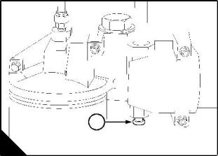
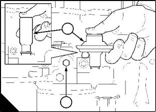
How to drain the cooling system
Warning! Do not drain the coolant while the engine is still hot and the system is under pressure because
dangerous hot coolant can be discharged.
1 Ensure that the machine is on level ground.
2 Remove the filler cap of the cooling system.
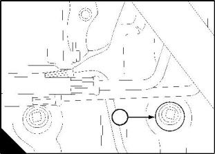
3 Remove the drain plug (A1) from the side of the cylinder block (below the rear of the high-pressure pump)
and the drain plug (B1) from the lubricating oil cooler in order to drain the engine. Ensure that the drain holes
are not restricted.
4 Open the tap or remove the drain plug at the bottom of the radiator in order to drain the radiator. If the radiator
does not have a tap or drain plug, disconnect the hose at the bottom of the radiator.
5 Flush the system.
6 Fit the drain plugs and the filler cap. Close the radiator tap or connect the radiator hose.
7 Renew the canister, part number 26550001, of the coolant filter.
Caution: The canister contains a corrosion inhibitor which is circulated around the cooling system as the
coolant passes through the canister. It is important that only the genuine correct Perkins canister is used.
1
1
A
B
W005
W006
User’s Handbook, TPD 1352E, issue 4
19
This document is printed from SPI². Not for RESALE
![]()
![]()
4
1300 Series EDi Models WK to WS
How to fill the cooling system
Caution: See "Coolant specification" on page 31 for details of the correct coolant to be used in the cooling
system. If coolant is added to the system during service, it must consist of the same original mixture as used
to fill the system. The engine must be allowed to cool before coolant is added.
Warning! Do not remove the filler cap while the engine is still hot and the system is under pressure because
dangerous hot coolant can be discharged.
1 Remove the filler cap of the cooling system.
2 The cooling system must be filled very slowly in order to eliminate air. Fill the cooling system until coolant
reaches the bottom of the filler tube. Fit the filler cap.
3 Start the engine. Allow the engine to operate at a fast idle until the engine reaches its normal temperature
of operation. Stop the engine and allow it to cool.
Remove carefully the filler cap and add coolant until the level of the coolant reaches the filler tube. Fit the filler
cap.
20
User’s Handbook, TPD 1352E, issue 4
This document is printed from SPI². Not for RESALE
![]()
![]()
4
1300 Series EDi Models WK to WS
How to renew the canister of the coolant filter / inhibitor
Warning! Do not remove the canister while the engine is still hot and under pressure because dangerous hot
fluid can be discharged.
Caution: The canister contains a corrosion inhibitor which is circulated around the cooling system as the
coolant passes through the canister. It is important that only the genuine correct Perkins canister is used.
Note: There are two types of coolant filter head:
Type 1
1 When the engine has cooled, remove the radiator filler cap to release the system pressure.
Note: When the system pressure is released, valves will close in the filter canister and in the housing for the
canister. This will prevent the loss of coolant when the filter is removed.
2 Thoroughly clean the outside surfaces of the coolant filter assembly.
3 Use a strap wrench or similar tool to loosen the filter canister and remove the canister. Valves in the filter
head will prevent the loss of coolant when the canister is removed.
4 Ensure that the threaded adaptor (A2) is secure in the filter head and that the inside of the head is clean.
5 Lubricate lightly the seal (A1) on top of the new canister with clean engine coolant. Fit the new canister to
the filter head and tighten, by hand only. Do not overtighten the canister.
1
2
3
1
2
A
B
W007
W1170
Type 2
1 When the engine has cooled, remove the radiator filler cap to release the system pressure.
2 Turn the lever (B1) fully counter-clockwise, to the close the valve. This will prevent the loss of coolant when
the canister (B3) is removed.
3 Thoroughly clean the outside surfaces of the coolant filter assembly.
4 Use a strap wrench or similar tool to loosen the filter canister and remove the canister.
5 , , Lubricate lightly the seal on top of the new canister with clean engine coolant. Fit the new canister to the
filter head and tighten until the seal touches the filter head, tighten a further one rotation by hand only. Do not
overtighten the canister.
6 Turn the lever (B2) fully clockwise, to the open the valve. This will allow the flow of coolant through the
canister.
User’s Handbook, TPD 1352E, issue 4
21
This document is printed from SPI². Not for RESALE
![]()
![]()
4
1300 Series EDi Models WK to WS
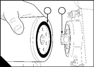
How to check the drive belt
There is no need to check the tension of the belt as the tension is set automatically. The condition of the belt
should be checked. The belt should be renewed if there are cracks in the belt or if the belt is contaminated by
oil or grease.
1
4
2
5
3
A
W008
How to remove the drive belt
1 Fit a square headed lever (A3) into the 12,7 mm (0.5 in) hole (A2) in the tensioner assembly (A1).
2 Operate the lever to release the tension from the belt (A4) and remove the belt. The tensioner will return to
its original position by spring pressure.
3 Remove the lever.
To tighten the alternator pulley nut
1 Fit a suitable strap wrench around the alternator pulley to prevent rotation while the nut is tightened.
2 Tighten the nut to 60 Nm (44 lbf ft) 6 kgf m.
3 Remove the strap wrench.
To fit the fan drive belt
1 With the lever (A3) in the tensioner (A1), pull the tensioner outwards. Put the belt in position around all of
the pulleys. Ensure that the tensioner pulley is on the outside of the belt.
2 Allow the tensioner to return and tension the belt.
3 Remove the lever.
22
User’s Handbook, TPD 1352E, issue 4
This document is printed from SPI². Not for RESALE
![]()
![]()

4
1300 Series EDi Models WK to WS
Fuel pre-filter
This will normally be fitted between the fuel tank and the engine. Check the filter bowl for water at regular
intervals and drain as necessary.
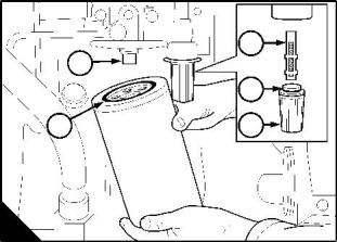
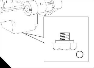
How to renew the fuel strainer and the canister of the fuel filter
The fuel filter assembly has a fuel strainer to remove larger particles from the fuel and a filter canister to remove
the smaller particles. The fuel strainer can be cleaned, but the fuel filter must be renewed.
1 Thoroughly clean the outside surfaces of the fuel filter assembly.
2 Use a strap wrench or similar tool to loosen the filter canister, and remove the canister.
1
3 Use a 29 mm (1 / in ) socket spanner to remove the plastic cover (A5) from the fuel strainer. Remove the
8
strainer (A3) and the 'O' ring (A4) from the cover.
4 Fit a new strainer and a new 'O' ring to the cover and fit the cover to the filter head.
Caution: Ensure that the open end of the new strainer is toward the filter head.
5 Ensure that the threaded adaptor (A1) is secure in the filter head and that the inside of the head is clean.
Lubricate lightly the seal (A2) of the new canister with clean diesel fuel. Fit the new canister to the filter head
1
and tighten the canister by hand until the seal contacts the filter head. Tighten the canister a further / turn by
2
hand only. Do not use a strap wrench.
6 Eliminate the air from the fuel filter, see page 24.
Caution: It is important that only the genuine Perkins parts are used. The use of wrong parts could damage
the fuel injector units.
3
1
4
2
5
A
W009
User’s Handbook, TPD 1352E, issue 4
23
This document is printed from SPI². Not for RESALE
![]()
![]()
4
1300 Series EDi Models WK to WS
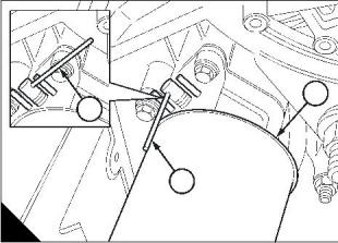
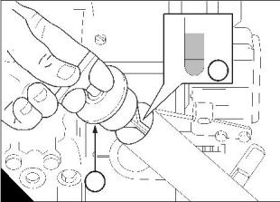
How to eliminate air from the fuel system
If air enters the fuel system, it must be eliminated before the engine can be started.
Air can enter the system if:
z The fuel tank is drained during normal operation.
z The low-pressure fuel pipes are disconnected.
z A part of the low-pressure fuel system leaks during engine operation.
In order to eliminate air from the fuel system, proceed as follows:
1 Loosen the vent plug (A1) on the top of the fuel filter head.
2 Operate the plunger of the fuel priming pump (A2) until fuel, free from air, comes from the filter vent point.
Tighten the vent plug.
3 Turn the start key to the "ON" position.
4 Operate the starter motor for intervals of 15 seconds until the engine starts. If the engine runs correctly for
a short time and then stops or runs roughly, check for air in the fuel system. If there is air in the fuel system,
there is probably a leakage in the low pressure system. Turn the start key to the "OFF" position to stop the
engine. Rectify the leakage and repeat the procedure.
2
1
A
W011/1
24
User’s Handbook, TPD 1352E, issue 4
This document is printed from SPI². Not for RESALE
![]()
![]()
4
1300 Series EDi Models WK to WS
How to renew the lubricating oil
1 Operate the engine until it is warm.
2 Stop the engine.
3 Put a container with a capacity of approximately 30 litres (6.5 UK gallons) 32 US quarts beneath the sump.
Remove the sump drain plug (A1) and its washer and drain the lubricating oil from the sump. Ensure that the
‘O’ ring is not damaged. Fit the drain plug and its washer and tighten the plug to 68 Nm (50 lbf ft) 6,9 kgf m.
4 Turn the handle on top of the filler cap (B2) counter-clockwise to release the filler cap and dipstick assembly
from the filler tube.
5 Fill the sump to the "FULL" mark on the dipstick (B1) with new and clean lubricating oil of an approved grade,
see "Lubricating oil specification" on page 30.
6 Fit the dipstick and filler cap assembly and turn the handle on the cap clockwise to tighten the filler cap in
the filler tube.
7 Remove the container of used lubricating oil from beneath the engine.
Warning! Discard the used lubricating oil in a safe place and in accordance with local regulations.
8 Start the engine and check for lubricating oil leakage. Stop the engine. After 15 minutes check the oil level
on the dipstick and, if necessary, put more lubricating oil into the sump.
Caution: Do not fill the sump past the "FULL" mark on the dipstick.
F u l l
A d d
1
1
2
A
B
W012
W013
User’s Handbook, TPD 1352E, issue 4
25
This document is printed from SPI². Not for RESALE
![]()
![]()
4
1300 Series EDi Models WK to WS
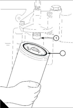
How to renew the canister of the lubricating oil filter
1 Put a tray under the filter to retain spilt lubricating oil.
2 Clean thoroughly the outside surfaces of the filter assembly.
3 Use a strap wrench or similar tool to loosen the filter canister. Remove and discard the canister. Ensure that
the adaptor (A1) is secure in the filter head.
Warning! Discard the used canister and lubricating oil in a safe place and in accordance with local regulations.
4 Clean inside the filter head
5 Lubricate the seal (A2) on top of the canister with clean engine lubricating oil.
6 Fill the new filter canister with clean engine lubricating oil. Fit the new canister and tighten by hand until the
1
3
4
seal contacts the filter head. Tighten the canister a further / to / of a turn by hand only. Do not use a strap
wrench.
2
7 Ensure that there is lubricating oil in the sump.
8 Turn the start key to the "ON" position and start the engine.
Note: The engine will not start and operate until oil pressure is obtained. Oil pressure is indicated when the
warning light is extinguished or by a reading on the gauge.
When the engine starts check for leakage from the filter. Stop the engine. After 15 minutes check the oil level
on the dipstick and, if necessary, put more lubricating oil of an approved grade into the sump.
Caution: Do not fill the sump past the "FULL" mark on the dipstick.
2
A
W014
26
User’s Handbook, TPD 1352E, issue 4
This document is printed from SPI². Not for RESALE
![]()
![]()
4
1300 Series EDi Models WK to WS
Air filter
Environmental conditions have an important effect on the frequency at which the air filter needs service.
The filter element must be cleaned or renewed according to the manufacturer's recommendations.
Restriction indicator
The restriction indicator for these engines must work at a pressure difference of 635 mm (25 in) of water gauge.
It is fitted on the air filter outlet or between the air filter and the induction manifold.
The restriction indicator should be tested according to the manufacturer's recommendations.
User’s Handbook, TPD 1352E, issue 4
27
This document is printed from SPI². Not for RESALE
![]()
![]()
4
1300 Series EDi Models WK to WS
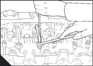
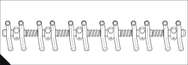
How to set the valve tip clearances
The valve tip clearance is checked with feeler gauges between the top of the valve stem and the rocker lever
(B), with the engine cold. The correct clearance for the inlet valves and the exhaust valves is 0,64 mm
(0.025 in). The valve positions are shown at (A).
The arrangement of the valves for each cylinder in sequence is inlet valve then exhaust valve.
Note: Number 1 cylinder is at the front of the engine.
1 Disconnect the air inlet pipe at the rocker cover/induction manifold.
2 Release the 13 cap screws which retain the rocker cover and remove the cover.
3 Turn the crankshaft in the normal direction of rotation until valve 11 (A) has just opened and valve 12 has
not closed fully. Check/adjust the clearances of valves 1 and 2.
4 Set valves 3 and 4 as indicated above then check/adjust the clearances of valves 9 and 10.
5 Set valves 7 and 8 then check/adjust the clearances of valves 5 and 6.
6 Set valves 1 and 2 then check/adjust the clearances of valves 11 and 12.
7 Set valves 9 and 10 then check/adjust the clearances of valves 3 and 4.
8 Set valves 5 and 6 then check/adjust the clearances of valves 7 and 8.
9 If necessary, put a new rocker cover/induction manifold gasket in position on the cylinder head. Align
carefully the cover and the gasket. Fit the cap screws which retain the rocker cover and tighten them to 17 Nm
(13 lbf ft) 1,7 kgf m.
10 Connect the air inlet pipe to the rocker cover
1
2
3
4
5
6
7
8
9
10
11
12
A
W014
B
W202/1
28
User’s Handbook, TPD 1352E, issue 4
This document is printed from SPI². Not for RESALE
![]()
![]()
1300 Series EDi Models WK to WS
5
Engine fluids
5
Fuel specification
To get the correct power and performance from your engine, use good quality fuel. The recommended fuel
specification for Perkins engines is indicated below:
Cetane number
Viscosity
50 minimum
2.0/4.5 centistokes at 40 °C
0,835/0,855 kg/litre
0.2% of mass, maximum
85% at 350 °C
Density
Sulphur
Distillation
Cetane number indicates ignition performance. A fuel with a low cetane number can cause cold start problems
and affect combustion.
Viscosity is the resistance to flow and engine performance can be affected if it is outside the limits.
Density: A lower density reduces engine power, a higher density increases engine power and exhaust smoke.
Sulphur: A high sulphur content (not normally found in Europe, North America or Australasia) can cause
engine wear. Where only high sulphur fuels are available, it is necessary to use a highly alkaline lubricating oil
in the engine or to renew the lubricating oil more frequently, see "How to renew the lubricating oil" on page 25.
Distillation: This is an indication of the mixture of different hydrocarbons in the fuel. A high ratio of light-weight
hydrocarbons can affect the combustion characteristics.
Low temperature fuels
Special winter fuels may be available for engine operation at temperatures below 0 °C. These fuels have a
lower viscosity and also limit the wax formation in the fuel at low temperatures. If wax formation occurs, this
could stop the fuel flow through the filter.
If you need advice on adjustments to an engine setting or to the lubricating oil change periods which may be
necessary because of the standard of the available fuel, consult the Technical Service Department of Perkins
International Limited at Peterborough or your nearest Perkins Distributor.
Aviation kerosene fuels
Caution: Do not use aviation kerosene fuel JP4.
JP5 and JP8 can be used, but they can affect engine performance and wear in the fuel injector units could
increase. It is recommended that you consult the Technical Service Department of Perkins International
Limited at Peterborough if aviation kerosene fuel is to be used.
Aviation kerosene fuels are more flammable than diesel fuel and need careful storage and careful
management.
User’s Handbook, TPD 1352E, issue 4
29
This document is printed from SPI². Not for RESALE
![]()
![]()
5
1300 Series EDi Models WK to WS
Lubricating oil specification
The specification of lubricating oil that is recommended for these engines are API CI-4 or DHD-1.
This specification of lubricating oil will provide the necessary protection for your engine. A higher specification
of lubricating oil is acceptable.
Caution: The type of lubricating oil to be used may be affected by the quality of the fuel which is available. For
further details see "Fuel specification" on page 29.
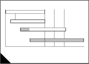
Always ensure that the correct viscosity grade of lubricating oil is used for the ambient temperature range in
which the engine will run as shown in the chart (A).
Note: The shaded areas in the chart (A) indicate the preferred viscosity grade of oil for the temperature range.
Increase in oil consumption may be expected when SAE 0W-30, 5W-30 and 10W-30 oils are used.
Check oil levels more frequently.
0W-30
5W-30
10W-30
15W-40
-30
-22
-20
-4
-10
14
0
32
10
50
20
68
30
86
40
50 C
o
o
104 122 F
A
30
User’s Handbook, TPD 1352E, issue 4
This document is printed from SPI². Not for RESALE
![]()
![]()
5
1300 Series EDi Models WK to WS
Coolant specification
The quality of the coolant which is used can have a great effect on the efficiency and life of the cooling system.
The recommendations indicated below can help to maintain a good cooling system and to protect it against
frost and/or corrosion.
If the correct procedures are not used, Perkins cannot be held responsible for frost or corrosion damage.
1 If it is possible, use clean soft water in the coolant.
2 If an antifreeze mixture is used to prevent frost damage, it must have an ethanediol base (ethylene glycol)
with a corrosion inhibitor. It is recommended that the corrosion inhibitor is of the sodium nitrite/sodium
molybdate type. The antifreeze mixture must be an efficient coolant at all ambient temperatures and it must
provide protection against corrosion. It must also have a specification at least as good as the requirements of
either BS6580 or MOD AL39.
The quality of the antifreeze coolant must be checked at least once a year, for example, at the beginning of
the cold period. The coolant must be renewed every two years.
The antifreeze mixture must consist of equal quantities of antifreeze and water. Concentrations of more than
50% of antifreeze must not be used because these can affect adversely the performance of the coolant.
3 When frost protection is not necessary, it is still an advantage to use an approved antifreeze mixture
because this gives a protection against corrosion and also raises the boiling point of the coolant. If an approved
antifreeze mixture is not available, add a correct mixture of corrosion inhibitor to the water.
All 1300 Series EDi engines are supplied with a coolant filter / conditioner canister. Renew the coolant and the
filter / conditioner canister in accordance with the maintenance "Schedules" on page 18. Test the level of
coolant conditioner, and adjust if necessary in accordance with the maintenance "Schedules" on page 18.
User’s Handbook, TPD 1352E, issue 4
31
This document is printed from SPI². Not for RESALE
![]()
![]()
This page is intentionally blank
This document is printed from SPI². Not for RESALE
1300 Series EDi Models WK to WS
6
Fault diagnosis
6
Problems and possible causes
Possible causes
Problem
Checks by the workshop
personnel
Checks by the user
The starter motor turns the engine too slowly
The engine does not start
1, 2, 3, 4
5, 6, 7, 8, 9, 10, 12, 13, 37, 38, 42, 43, 44, 66, 67, 68,
14, 15, 17
69
5, 7, 8, 9, 10, 11, 12, 13,
14, 15, 16, 17, 19
The engine is difficult to start
Not enough power
37, 38, 40, 42, 43, 44, 66
8, 9, 10, 11, 12, 13, 16, 37, 38, 39, 42, 43, 44, 61, 63,
8, 9, 20, 21
64, 66, 68, 69
8, 9, 10, 12, 13, 15, 20,
22
Misfire
37, 38, 39, 40, 43, 66, 69
11, 13, 15, 17, 18, 19,
23, 22
37, 38, 39, 40, 42, 43, 44, 63,
66
High fuel consumption
Black exhaust smoke
Blue or white exhaust smoke
37, 38, 39, 40, 42, 43, 44, 61,
63, 66
11, 13, 15, 17, 19, 21, 22
4, 15, 21, 23
37, 38, 39, 42, 43, 44, 45, 52,
58, 62, 66, 68
The pressure of the low pressure lubricating oil system is too
low
4, 24, 25, 26
46, 47, 48, 50, 51, 59,
37, 40, 42, 44, 46, 52, 53, 60,
66, 68
The engine knocks
The engine runs erratically
Vibration
9, 13, 15, 17, 20, 22, 23
8, 9, 10, 11, 12, 13, 15,
16, 18, 20, 22, 23
38, 40, 44, 52, 60, 66, 68, 69
38, 39, 40, 44, 52, 54, 66, 68,
69
13, 18, 20, 27, 28
4, 25
The pressure of the low pressure lubricating oil system is too
high
49
11, 13, 15, 19, 27, 29,
30, 32, 65
The engine oil temperature is too high
Crankcase pressure
37, 39, 52, 55, 56, 57, 64, 69
39, 42, 44, 45, 52
31, 33
37, 39, 40, 42, 43, 44, 45, 53,
60
Bad compression
11, 22
The engine starts and stops
10, 11, 12
4, 24, 25, 26
66, 68, 69
The pressure of the high pressure lubricating oil system is too
low
66, 68, 69
User’s Handbook, TPD 1352E, issue 4
33
This document is printed from SPI². Not for RESALE
![]()
![]()

6
1300 Series EDi Models WK to WS
List of possible causes
1 Battery capacity low.
2 Bad electrical connections.
3 Fault in starter motor.
4 Wrong grade of lubricating oil.
5 Starter motor turns engine too slowly.
6 Fuel tank empty.
7 Spare.
8 Restriction in a fuel pipe.
9 Fault in fuel lift pump.
10 Dirty fuel filter element.
11 Restriction in air induction system.
12 Air in fuel system.
13 Fault in the fuel injector units.
14 Cold start system used incorrectly.
15 Fault in cold start system.
16 Restriction in fuel tank vent.
17 Wrong type or grade of fuel used.
18 Restricted movement of engine speed control.
19 Restriction in exhaust pipe.
20 Engine temperature is too high.
21 Engine temperature is too low.
22 Incorrect valve tip clearances.
23 Too much oil or oil of the wrong type is used in wet type air cleaner, if one is fitted.
24 Not enough lubricating oil in sump.
25 Defective gauge.
26 Dirty lubricating oil filter element.
27 Fan damaged.
28 Fault in engine mounting or flywheel housing.
29 Too much lubricating oil in sump.
30 Restriction in air or water passages of radiator.
31 Restriction in breather pipe.
32 Insufficient coolant in system.
33 Fault in exhauster.
34 Spare.
35 Spare.
36 Spare.
37 Valve timing is incorrect.
38 Bad compression.
39 Cylinder head gasket leaks.
40 Valves are not free.
41 Spare.
42 Worn cylinder bores.
43 Leakage between valves and seats.
44 Piston rings are not free or they are worn or broken.
45 Valve stems and/or guides are worn.
46 Crankshaft bearings are worn or damaged.
34
User’s Handbook, TPD 1352E, issue 4
This document is printed from SPI². Not for RESALE
![]()
![]()
6
1300 Series EDi Models WK to WS
47 Lubricating oil pump is worn.
48 Relief valve does not close.
49 Relief valve does not open.
50 Relief valve spring is broken.
51 Fault in suction pipe of lubricating oil pump.
52 Piston is damaged.
53 Piston height is incorrect.
54 Flywheel housing or flywheel is not aligned correctly.
55 Fault in thermostat or thermostat is of an incorrect type.
56 Restriction in coolant passages.
57 Fault in water pump.
58 Valve stem seal is damaged.
59 Restriction in sump strainer.
60 Valve spring is broken.
61 Turbocharger impeller is damaged or dirty.
62 Lubricating oil seal of turbocharger leaks.
63 Induction system leaks.
64 Turbocharger waste-gate does not work correctly, if one is fitted.
65 Drive belt for water pump is loose.
66 Faulty engine management system.
67 Broken drive on the high pressure pump.
68 Faulty injection control system
69 Faulty sensor
免费热线
400-100-8969 15088860848
400-100-8969 15088860848
机组销售
0574-26871589 15267810868
0574-26871589 15267810868
配件销售
0574-26886646 15706865167
0574-26886646 15706865167
维修热线
0574-26871569 18658287286
0574-26871569 18658287286
手机端

微信公众号