 English
 Espaol
 Franais
 阿拉伯
阿拉伯 中文(简)
中文(简) Deutsch
 Italiano
 Português
 日本
日本 韩国
韩国 български
 hrvatski
 esky
esky Dansk
Dansk Nederlands
 suomi
suomi Ελληνικ
 印度
印度 norsk
norsk Polski
 Roman
Roman русский
 Svenska
 珀金斯Perkins1506A-E88TA、1506C-E88TA、1506D-E88TA发动机维修技术资料,珀金斯Perkins1506A-E88TA、1506C-E88TA、1506D-E88TA发动机维修技术资料技术支持中心,珀金斯Perkins1506A-E88TA、1506C-E88TA、1506D-E88TA发动机维修技术资料代理商,珀金斯Perkins1506A-E88TA、1506C-E88TA、1506D-E88TA发动机维修技术资料销售服务中心,珀金斯Perkins1506A-E88TA、1506C-E88TA、1506D-E88TA发动机维修技术资料价格规格资料查询,宁波日昕动力科技有限公司

珀金斯Perkins1506A-E88TA、1506C-E88TA、1506D-E88TA发动机维修技术资料
详细描述
2. Lubricate the main bearing cap bolts. Use SAE
30W oil or molybdenum grease to lubricate the
threads and the washer face.
Table 1
Required Tools
Tool
Part Number
Part description
3. Torque the main bearing cap bolts to 95 ± 5 N·m
(70 ± 4 lb ft).
A
-
Loctite 575
4. Put an alignment mark on each cap and bolt.
5. Rotate the bolts in the clockwise direction to an
angle of 90 ± 5 degrees.
Illustration 56
g01418610
View H-H
NOTICE
Camshaft bearings must be installed into their correct
position. Failure to do so will result in engine damage.
The camshaft bearings are installed into the cylinder
block at the following positions:
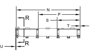
Illustration 57
g01418223
Typical example
Position (N) ..............................816.50 ± 0.80 mm
(32.146 ± 0.031 inch)
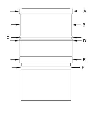
Note: Apply Tooling (A) to the cylinder liner seals
prior to assembly.
Position (P) ..............................536.50 ± 0.80 mm
(21.122 ± 0.031 inch)
Outside diameters of the cylinder liner
Position (S) ..............................294.50 ± 0.80 mm
(11.594 ± 0.031 inch)
Position (T) ..................................0.50 ± 0.25 mm
(0.020 ± 0.010 inch)
Position (A) ..............................128.95 ± 0.03 mm
(5.077 ± 0.001 inch)
Position (B) ..............................123.80 ± 0.30 mm
(4.874 ± 0.012 inch)
Position (C) ..............................123.95 ± 0.13 mm
(4.880 ± 0.005 inch)
Position (D) ..............................126.00 ± 0.27 mm
(4.961 ± 0.011 inch)
(U) Installation depth of the cup plug from the block
face to the top edge of the plug .......... 1.25 ± 0.25 mm
(0.049 ± 0.010 inch)
Position (E) ..............................126.24 ± 0.03 mm
(4.970 ± 0.001 inch)
Position (F) ..............................120.34 ± 0.08 mm
(4.738 ± 0.003 inch)
i05966841
Cylinder Liner
Bore diameter for the cylinder liner
...............112.025 ± 0.025 mm (4.4104 ± 0.0010 inch)
This document has been printed from SPI2. NOT FOR RESALE
![]()
![]()
![]()
![]()
![]()
![]()
![]()
30
UENR4509
Specifications Section
i06001291
Crankshaft
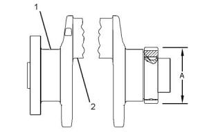
Illustration 59
g01418240
(4) O-ring seal
(5) Bolt
Illustration 58
g01384054
Typical example
(1) Main bearing journals
(2) Connecting rod bearing journals
(A) Average diameter of gear after assembly
........................112.48 ± 0.10 mm (4.428 ± 0.004 inch)
Maximum diameter of gear after assembly
............................................... 112.63 mm (4.434 inch)
Crankshaft end play after assembly into cylinder
block ................ 0.21 to 0.60 mm (0.008 to 0.024 inch)
i02844263
Crankshaft Seals
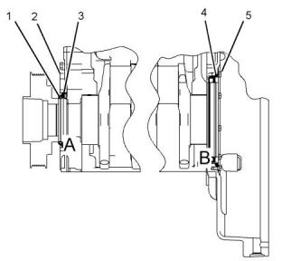
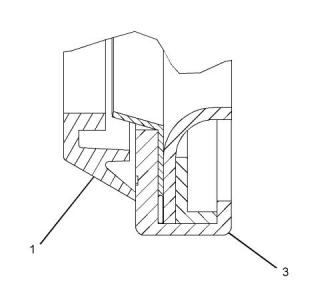
Illustration 60
g01123043
Detail A
Note: Refer to Disassembly and Assembly for the
complete procedure that is used for information that
relates to the removal and the installation of the front
and the rear crankshaft seals.
Note: The crankshaft seal excluder (1) can be
installed with the front seal for use in applications that
operate in harsh environments. If the extruder is used
on your application, lubricate the inside diameter of
the crankshaft seal excluder with liquid soap prior to
assembly to the crankshaft pulley.
This document has been printed from SPI2. NOT FOR RESALE
![]()
![]()
![]()
![]()
![]()
![]()
![]()
UENR4509
31
Specifications Section
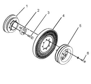
When the front crankshaft seal (3) is installed, the
front face of the seal must be 2.5 mm (0.10 inch)
from the face of the front housing (2).
Illustration 62
g03744724
Typical example
(1) Crankshaft adapter
(2) Adapter
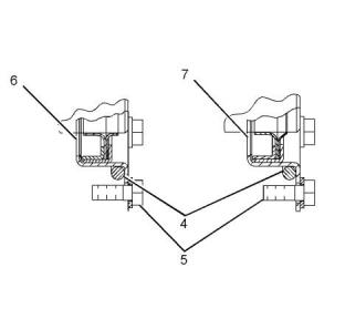
Illustration 61
g01419999
Detail B
(4) Damper
(5) Pulley
(7) Rear crankshaft seal group with dust lip
(3) Tighten the bolts to the following torque.
........................................................160 N·m (118 lb ft)
Note: The rear crankshaft seal group (6) is a double
lipped seal that is used for wet flywheel housing
applications.
(6) Tighten the bolts to the following torque......55 N·m
(41 lb ft)
i05976176
Vibration Damper and Pulley
i05970980
Connecting Rod Bearing
Journal
Table 2
ConnectingRod Bearing Journal
Original size journal
80.000 ± 0.020 mm
(3.1496 ± 0.0008 inch)
i05970918
Main Bearing Journal
This document has been printed from SPI2. NOT FOR RESALE

![]()
![]()
![]()
![]()
![]()
32
UENR4509
Specifications Section
Table 3
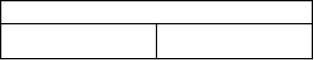
(A) Bore in the bearing for the piston pin
.................46.035 ± 0.008 mm (1.8124 ± 0.0003 inch)
Diameter of CrankshaftJournal (Bearing Surface) for Main
Bearings
(B) Bore in the connecting rod for the piston pin
104.000 ± 0.020 mm
Original size journal
bearing..... 50.640 ± 0.013 mm (1.9937 ± 0.0005 inch)
(4.0945 ± 0.0008 inch)
(C) The bearing joint must be within ± 5 degrees of
either location.
Undersized journal 0.25 mm
(0.00984 inch)
103.75 ± 0.02 mm
(4.08464 ± 0.00079 inch)
Note: The connecting rod must be heated for the
installation of the piston pin bearing. Do not use a
torch.
Undersized journal
0.51 mm (0.02008 inch)
103.49 ± 0.02 mm
(4.07440 ± 0.00079 inch)
Table 4
(D) The connecting rod may be heated from
Main Bearing Bore
175 to 260 °C (347 to 500 °F) for the installation of
the piston pin bearing. Maximum distance for heating
the connecting rod....................... 83.0 mm (3.27 inch)
Main bearing bore (original size)
112.000 ± 0.013 mm
(4.4094 ± 0.0005 inch)
Note: Thoroughly lubricate the piston pin with clean
engine oil prior to assembly of the piston and
connecting rod.
i02840023
Connecting Rod
(E) Distance between the center of the bearings
...............................................217.00 mm (8.543 inch)
(G) Bore in the connecting rod for the crankshaft
bearing..... 85.000 ± 0.013 mm (3.3465 ± 0.0005 inch)
Illustration 64
g01416591
View F-F
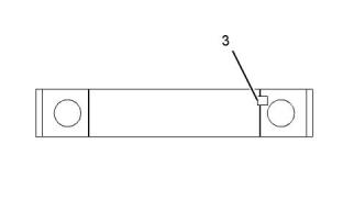
(1) Etch the cylinder number on the connecting rod
and the cap in this location. Mark the connecting rod
and the cap with a number 1 through 6. Mark the
numbers on the same side of the connecting rod as
the bearing retainer notch (3).
Note: Install the rod and piston group in the engine
with the part number of the forging for the rod
assembly to the rear of the engine. The rear of the
engine is the flywheel end of the engine. Lubricate
the rod and piston group with clean engine oil before
you insert the rod and piston group into the block.
Illustration 63
g01418268
Note: Handle the fractured connecting rod with care.
Use a soft jawed vise in order to hold the connecting
rod when you are loosening the connecting rod cap
bolts. Use a soft faced hammer in order to tap the
connecting rod cap, if necessary.
(2) Use the following procedure to tighten the
connecting rod bolts:
1. Torque the bolts to 50 ± 5 N·m (37 ± 4 lb ft).
This document has been printed from SPI2. NOT FOR RESALE

![]()
![]()
![]()
![]()
![]()
UENR4509
33
Specifications Section
2. Rotate each bolt in a clockwise direction for 90 ± 5
Top Ring and Intermediate Ring
degrees (1/4 of a turn).
(3) The top ring has the mark “UP-1” .
i02156012
Install the piston ring with the side marked “UP-1”
toward the top of the piston. The colored stripe faces
to the right of the ring end gap.
Piston and Rings
Piston ring end gap............................. 0.40 ± 0.10 mm
( 0.016 ± 0.004 inch)
Thickness of new top piston ring .................3.453 mm
(0.1359 inch)
Two-Piece Articulated Piston
(4) The intermediate ring has the mark “UP-2” .
Install the piston ring with the side marked “UP-2”
toward the top of the piston. The colored stripe faces
to the right of the piston ring end gap.
Piston ring end gap............................. 1.50 ± 0.10 mm
(0.060 ± 0.004 inch)
Width of groove in new piston for intermediate piston
ring.....................3.06 ± 0.01 mm (0.121 ± 0.001 inch)
Thickness of new intermediate piston ring .... 2.98 mm
(0.117 inch)
Illustration 65
g00293184
Oil Control Ring
(5) The oil control piston ring has a spring that is
installed with the ring. The gap in the spring should be
a distance of 180 degrees from the ring end gap
when the oil control piston ring is assembled. The
colored portion can be to the right or to the left of the
ring end gap.
Piston ring end gap............................. 0.45 ± 0.15 mm
(0.018 ± 0.006 inch)
Width of groove in new piston for oil control piston
ring.....................4.03 ± 0.01 mm (0.159 ± 0.001 inch)
Thickness of new oil control piston ring
........................... 3.98 ± 0.01 mm (0.157 ± 0.001 inch)
After the piston rings have been installed, rotate the
piston rings so that the end gaps are 120 degrees
from each other.
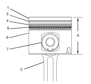
(6) Piston skirt
Lubricate the entire piston in zone (A) prior to
assembly into the cylinder block. Use clean engine
oil.
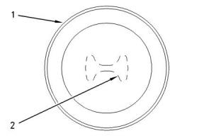
Illustration 66
g01093113
(1) Crown assembly
(2) Connecting rod
Piston Pin
Note: Install the rod and piston group in the engine
with the part number of the forging for the rod
(7) Piston pin
assembly to the rear of the engine. The rear of the
engine is the flywheel end of the engine. Lubricate
the rod and piston group with clean engine oil before
you insert the rod and piston group into the block.
Piston pin diameter ................46.000 ± 0.005 mm
(1.8110 ± 0.0002 inch)
Length of piston pin....................91.50 ± 0.15 mm
(3.602 ± 0.006 inch)
This document has been printed from SPI2. NOT FOR RESALE
![]()
![]()
![]()
![]()
![]()
34
UENR4509
Specifications Section
Thoroughly lubricate the piston pin with clean engine
oil prior to assembly.
i02833773
Piston Cooling Jet
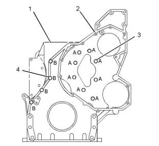
Illustration 68
g01405402
Typical example
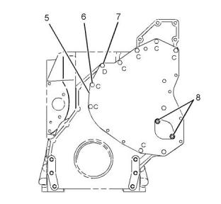
(1) Cylinder block
(2) Front housing
Illustration 67
g01412616
Apply Loctite Gasket Maker 518 to the front housing
sealing surfaces before assembling the front housing
to the cylinder block. The front housing must be
assembled and the front housing must be tightened to
the cylinder block within 10 minutes.
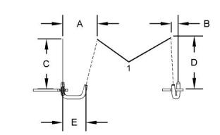
The piston cooling jet must be checked for the
location of the stream of oil. Insert a drill rod with a
diameter of 2 mm (0.1 inch) into the orifice. The drill
rod simulates the stream of oil under normal
operating pressure. The drill rod must pass through a
circle with a diameter of 5.0 mm (0.20 inch) at point
(1).
(3) Bolts
Length of the bolts that are marked for location
“A” ........................................ 20.0 mm (0.79 inch)
Tighten the bolts to the following torque.
Use the following dimensions in order to locate point
(1).
.....................................................28 N·m (21 lb ft)
Dimension (A) ...........................71.88 ± 0.25 mm
(2.830 ± 0.010 inch)
Dimension (B) ...........................16.07 ± 0.25 mm
(0.633 ± 0.010 inch)
Dimension (C) .........................120.00 ± 0.25 mm
(4.724 ± 0.010 inch)
(4) Bolts
Length of the bolts that are marked for location
“B” ........................................ 50.0 mm (1.97 inch)
Tighten the bolts to the following torque.
Dimension (D) .........................120.00 ± 0.25 mm
(4.724 ± 0.010 inch)
.....................................................28 N·m (21 lb ft)
Dimension (E) ...........................42.20 ± 0.25 mm
(1.661 ± 0.010 inch)
i06003749
Front Housing and Covers
This document has been printed from SPI2. NOT FOR RESALE
![]()
![]()
![]()
![]()
![]()
UENR4509
35
Specifications Section
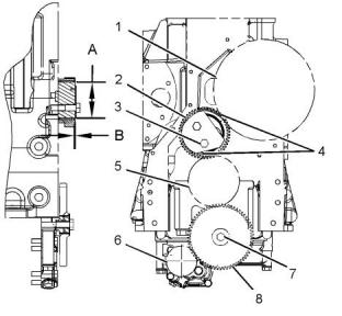
Illustration 69
g01405420
Illustration 70
g02112275
Typical example
(5) Front housing cover
Typical example
(6) Oil pump gear
(6) Bolts
(1) Camshaft gear
Length of the bolts that are marked for location
“C” ........................................30.0 mm (1.18 inch)
Tighten the bolts to the following torque.
Number of teeth .............................................. 100
Bore diameter...........................47.92 ± 0.013 mm
(1.89 ± 0.00051 inch)
.....................................................28 N·m (21 lb ft)
(2) Idler gear
(7) Bolt
Number of teeth ................................................ 50
Length of the bolt that is marked for location “D”
.............................................. 60.0 mm (2.36 inch)
Tighten the bolt to the following torque......28 N·m
(21 lb ft)
(A) Diameter of the idler shaft....... 74.000 ± 0.013 mm
(2.9134 ± 0.0005 inch)
(B) Installation depth of the bearing.... 1.08 ± 0.25 mm
(0.043 ± 0.01 inch)
(8) Apply Loctite 243 Threadlocker to the serrations
of the studs before installing the studs into the front
housing cover (5). Tighten the studs to the following
torque..................................................28 N·m (21 lb ft)
(3) Torque for the bolts for the idler gear...........70 N·m
(52 lb ft)
(5) Crankshaft gear
Tighten the nuts to the following torque............28 N·m
(21 lb ft)
Number of teeth ................................................ 50
Bore diameter.............................69.9 ± 0.025 mm
(2.75 ± 0.001 inch)
i05974922
Gear Group (Front)
(4) Align the timing marks on the idler gear (2) with
the holes on the camshaft gear (1) and the crankshaft
gear (5).
(7) Torque for the bolt for the oil pump idler gear
............................................................55 N·m (41 lb ft)
(8) Oil pump idler gear
Number of teeth ................................................ 60
End play of the oil pump idler gear
.................... 0.05 ± 0.35 mm (0.002 ± 0.014 inch)
This document has been printed from SPI2. NOT FOR RESALE
![]()
![]()
![]()
![]()
![]()
36
UENR4509
Specifications Section
i05975691
Table 5
Flywheel
Required Tools
Part Description
Liquid Gasket
Qty
Tool
Part Number
A
CH10879
1
Illustration 72
g03763388
Typical example
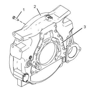
(2) Flywheel housing
(3) The joint face must be free of dirt, oil, fuel, water,
assembly compounds, or any other contaminants.
Apply a continuous film of Tooling (A) on the entire
face of the joint.
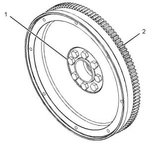
Illustration 71
g01103055
Typical example
Note: The flywheel housing must be assembled and
tightened to the cylinder block within 10 minutes of
the application of the gasket sealant.
(1) Torque for the eight bolts.......... 300 N·m (220 lb ft)
Note: The gear must be installed against the
shoulder of the flywheel.
(1) Tighten the bolts to the following torque.
..........................................................100 N·m (74 lb ft)
(2) Maximum temperature for the gear installation
............................................................315 °C (599 °F)
i05998995
Belt Tension Chart
i06003789
Flywheel Housing
Table 6
Required Tools
Tool
Part Number
Part Description
Qty
A
-
Belt Tension Gauge
1
This document has been printed from SPI2. NOT FOR RESALE

![]()
![]()
![]()
![]()
![]()
UENR4509
37
Specifications Section
Table 7
Fan Drive Belt Tension Chart
Gauge Reading
SAE or RMA Belt
Size
Width of Belt
Initial Belt Tension
(1)
Used Belt Tension
(2)
15/16
23.83 mm (0.94 inch)
912 N (205 lb)
730 N (164 lb)
Measure the tension of the belt that is farthest from the engine.
Initial Belt Tension refers to a new belt.
(1)
(2)
Used Belt Tension refers to a belt that has been in operation for 20 minutes or more at the rated speed.
Install Tooling (A) at the center of the longest free
length of belt and check the tension on the belt.
Check and adjust the tension on the tightest belt. To
adjust the belt tension, refer to Operation and
Maintenance Manual, “Belts - Inspect/Adjust”.
Note: When the belts are replaced, always replace
the belts as a set.
Table 8
Water Pump Drive Belt Tension Chart
Gauge Reading
SAE or RMA Belt
Size
Width of Belt
Initial Belt Tension
(1)
Used Belt Tension
(2)
1/2 or 13A
13.89 mm (0.55 inch)
734 N (165 lb)
580 N (130 lb)
Measure the tension of the belt that is farthest from the engine.
(1)
(2)
Initial Belt Tension refers to a new belt.
Used Belt Tension refers to a belt that has been in operation for 20 minutes or more at the rated speed.
Install Tooling (A) at the center of the longest free
length of belt and check the tension on the belt.
Check and adjust the tension on the tightest belt. To
adjust the belt tension, refer to Operation and
Maintenance Manual, “Belts - Inspect/Adjust”.
i06228918
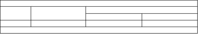
Belt Tensioner
(Model PK9)
Illustration 73
g03826878
Typical example
(1) Tighten the bolt to the following torque. ......55 N·m
(41 lb ft)
Spring force at assembly is the following value at 35
degrees from the free arm position.......59.9 ± 6.0 N·m
(44.2 ± 4.4 lb ft)
This document has been printed from SPI2. NOT FOR RESALE

![]()
![]()
![]()
38
UENR4509
Specifications Section
Minimum arm travel ..................................52 degrees
i06228915
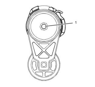
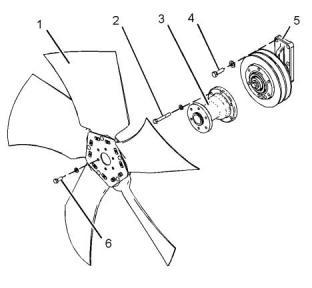
Refrigerant Compressor
(Model PK9)
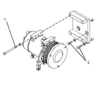
Illustration 75
g03744960
Typical example
(1) Fan
(3) Extension
(5) Fan drive assembly
(2) Tighten the bolts to the following torque......28 N·m
(21 lb ft)
(4) Tighten the bolts to the following torque......47 N·m
(35 lb ft)
(6) Tighten the bolts to the following torque......47 N·m
(35 lb ft)
Illustration 74
g03862998
Typical example
(1) Tighten the bolts to the following torque......28 N·m
(248 lb in)
i05967844
Alternator and Regulator
(2) Tighten the bolts to the following torque......28 N·m
(248 lb in)
i05976193
Fan Drive
This document has been printed from SPI2. NOT FOR RESALE
![]()
![]()
![]()
![]()
![]()
UENR4509
39
Specifications Section
Rotation ...............................................Either direction
Minimum full load current at 5000 rpm ........42.3 Amp
Minimum full load current at 2000 rpm ........15.8 Amp
Turn on speed ..............................................2500 rpm
Output voltage ............................................28 ± 1.0 V
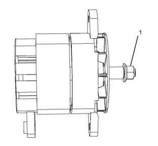
(1) Pulley nut.....................................102N·m (75 lb ft)
(2) Positive battery terminal..............6.2 N·m (55 lb in)
(4) Negative battery terminal ..........2.25 N·m (20 lb in)
i06229013
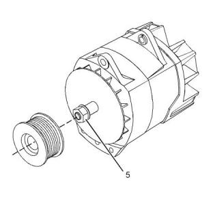
Alternator and Regulator
(Model PK9)
Illustration 76
g03741885
Typical example
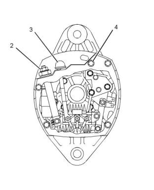
Illustration 78
g01332520
Typical example
Illustration 77
g03741886
Typical example
(3) R terminal
Voltage .................................................................24 V
Amperage .......................................................45 Amp
Polarity ..............................................Negative ground
This document has been printed from SPI2. NOT FOR RESALE
![]()
![]()
![]()
![]()
![]()
![]()
![]()
40
UENR4509
Specifications Section
Illustration 79
g03863028
Illustration 80
g03741867
Typical example
Typical example
Voltage .................................................................12 V
Amperage .....................................................160 Amp
(1) Terminal “L”
When the electric starting motor is viewed from the
drive end, the motor rotates in the following direction.
.....................................................................Clockwise
No load conditions at 25°C (77°F)
Tighten the terminal nut to the following torque.
..............................................3.1 N·m (27.43 lb in)
Minimum speed .....................................3000 rpm
Maximum output ........................................3.1 kW
Maximum current ........................................130 A
Voltage ..........................................................24 V
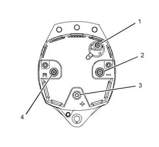
(2) The negative terminal “-”
Tighten the terminal nut to the following torque.
..........................................8.5 N·m (75.2314 lb in)
(2) Battery terminal
Tighten the nut on the battery terminal to the
following torque..................... 25.5 N·m (18.8 lb ft)
(3) The positive terminal “+”
Tighten the terminal nut to the following torque.
..........................................11.5 N·m (101.78 lb in)
(3) Ground terminal
Tighten the nut on the ground terminal to the
following torque..................... 25.5 N·m (18.8 lb ft)
(4) Terminal “R”
In order to install a different design of terminal,
tighten that terminal to the following torque.
..............................................3.7 N·m (32.75 lb in)
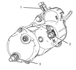
i06229010
Electric Starting Motor
(Model PK9)
(5) Pulley nut.....................................102 N·m (75 lb ft)
i05967799
Electric Starting Motor
This document has been printed from SPI2. NOT FOR RESALE
![]()
![]()
![]()
![]()
![]()
UENR4509
41
Specifications Section
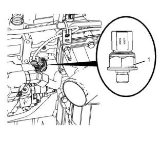
Illustration 82
g01291117
Typical example
(1) Sensor assembly
Tighten the sensor assembly to the following
torque...........................................20 N·m (15 lb ft)
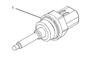
i02797035
Fuel Temperature Sensor
Illustration 81
g03863021
Typical example
When the electric starting motor is viewed from the
drive end, the motor rotates in the following direction.
.....................................................................Clockwise
Voltage .................................................................12 V
Maximum current ...............................................120 A
(1) Tighten the battery terminal to the following
torque...............................................25 N·m (221 lb in)
(2) Tighten the ground terminal to the following
torque...............................................25 N·m (221 lb in)
Tighten the “S” terminal to the following torque.
..........................................................2.5 N·m (22 lb in)
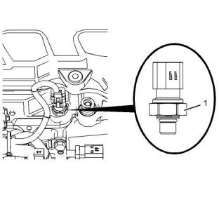
i02796276
Illustration 83
g01178443
Coolant Temperature Sensor
(1) Sensor assembly
Tighten the sensor assembly to the following
torque...............................20 ± 3 N·m (15 ± 2 lb ft)
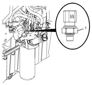
i05975064
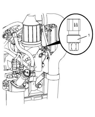
Fuel Pressure Sensor
This document has been printed from SPI2. NOT FOR RESALE
![]()

![]()
![]()

![]()
![]()
![]()
![]()
42
UENR4509
Specifications Section
Illustration 85
g03744213
Typical example
(1) Tighten the sensor to the following torque.
............................................................20 N·m (15 lb ft)
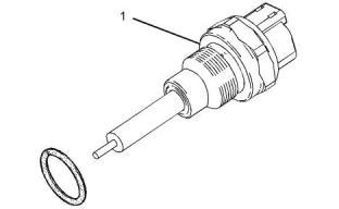
Illustration 84
g03744181
Typical example
i05970986
(1) Tighten the sensor to the following torque.
...........................................................10 N·m (90 lb in)
Engine Oil Pressure Sensor
i05974918
Injection Actuation Pressure
Sensor
This document has been printed from SPI2. NOT FOR RESALE
![]()
![]()
![]()
![]()
![]()
UENR4509
43
Specifications Section
Illustration 87
g03744017
Typical example
(1) Tighten the sensor to the following torque.
...........................................................10 N·m (90 lb in)
Illustration 86
g03743087
i02797079
Typical example
Inlet Air Temperature Sensor
(1) Tighten the sensor to the following torque.
...........................................................10 N·m (90 lb in)
i05971177
Atmospheric Pressure Sensor
Illustration 88
g01291117
Typical example
(1) Sensor assembly
Torque for sensor................................20 N·m (15 lb ft)
This document has been printed from SPI2. NOT FOR RESALE
![]()
![]()
![]()
![]()
![]()
![]()
![]()
44
UENR4509
Specifications Section
i05971152
Speed/Timing Sensor
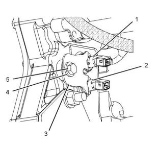
Illustration 90
g03744943
Typical example
(1) Tighten the allen head screw to the following
torque...................................................6 N·m (53 lb in)
(2) Tighten the screw to the following torque.
Illustration 89
g03743205
.........................................................12 N·m (106 lb in)
Typical example
(3) Tighten fasteners to the following torque.
............................................................28 N·m (21 lb ft)
(1) Camshaft position sensor
(2) Camshaft position sensor
(4) Washer
Ensure that the sensors are seated before the bolt is
tightened.
(3) Bracket
Ensure that the bracket is installed in the orientation
that is shown in illustration 89 .
(5) Tighten the bolt for the sensor to the following
torque..................................................28 N·m (21 lb ft)
i05976060
Electronic Control Module
This document has been printed from SPI2. NOT FOR RESALE
![]()
![]()
![]()

![]()
![]()
UENR4509
45
Index Section
Index
A
Fuel Temperature Sensor................................ 41
Air Inlet Elbow.................................................. 17
Alternator and Regulator.................................. 38
Alternator and Regulator (Model PK9)............. 39
Atmospheric Pressure Sensor......................... 43
G
Gear Group (Front).......................................... 35
I
B
Important Safety Information............................. 2
Injection Actuation Pressure Sensor ............... 42
Inlet Air Temperature Sensor........................... 43
Belt Tension Chart ........................................... 36
Belt Tensioner (Model PK9)............................. 37
C
L
Camshaft......................................................... 18
Connecting Rod............................................... 32
Connecting Rod Bearing Journal..................... 31
Coolant Temperature Sensor........................... 41
Crankcase Breather......................................... 21
Crankshaft....................................................... 30
Crankshaft Seals ............................................. 30
Cylinder Block.................................................. 27
Cylinder Block Cover Group............................ 27
Cylinder Head.................................................. 13
Cylinder Head Valves ...................................... 10
Cylinder Liner................................................... 29
Lifter Group........................................................ 8
M
Main Bearing Journal....................................... 31
P
Piston and Rings ............................................. 33
Two-Piece Articulated Piston....................... 33
Piston Cooling Jet............................................ 34
R
E
Refrigerant Compressor (Model PK9) ............. 38
Electric Starting Motor ..................................... 40
Electric Starting Motor (Model PK9) ................ 40
Electronic Control Module ............................... 44
Engine Design ................................................... 4
Engine Oil Filter Base...................................... 19
Engine Oil Pan................................................. 20
Engine Oil Pressure Sensor ............................ 42
Exhaust Manifold............................................. 18
S
Specifications Section ....................................... 4
Speed/Timing Sensor...................................... 44
T
Table of Contents............................................... 3
Turbocharger................................................... 15
Turbocharger (Model PK9).............................. 16
F
Fan Drive......................................................... 38
Flywheel .......................................................... 36
Flywheel Housing............................................ 36
Front Housing and Covers............................... 34
Fuel Filter Base (Primary Fuel Filter Base)........ 4
Fuel Filter Base (Secondary Fuel Filter
U
Unit Injector........................................................ 6
Unit Injector Hydraulic Pump............................. 6
Base, Model PK9)............................................ 5
Fuel Filter Base (Secondary Fuel Filter Base)... 5
Fuel Pressure Sensor...................................... 41
This document has been printed from SPI2. NOT FOR RESALE
![]()
46
UENR4509
Index Section
V
Valve Mechanism .............................................. 8
Valve Mechanism Cover.................................... 9
Vibration Damper and Pulley........................... 31
W
Water Pump..................................................... 24
Water Pump (Model PK9)................................ 26
Water Temperature Regulator ......................... 22
Water Temperature Regulator Housing..... 21–22
This document has been printed from SPI2. NOT FOR RESALE
免费热线
400-100-8969 15088860848
400-100-8969 15088860848
机组销售
0574-26871589 15267810868
0574-26871589 15267810868
配件销售
0574-26886646 15706865167
0574-26886646 15706865167
维修热线
0574-26871569 18658287286
0574-26871569 18658287286
手机端

微信公众号