 English
 Espaol
 Franais
 阿拉伯
阿拉伯 中文(简)
中文(简) Deutsch
 Italiano
 Português
 日本
日本 韩国
韩国 български
 hrvatski
 esky
esky Dansk
Dansk Nederlands
 suomi
suomi Ελληνικ
 印度
印度 norsk
norsk Polski
 Roman
Roman русский
 Svenska
 我们是***的Perkins1600发动机故障维修技术资料销售服务商,想要了解更多的Perkins1600发动机故障维修技术资料类型和资料,请现在联系我们!宁波日昕动力科技有限公司

Perkins1600发动机故障维修技术资料
详细描述
Specifications
1600 Series Industrial Engine
XGA (Engine)
XGB (Engine)
XGD (Engine)
XGE (Engine)
XGF (Engine)
XGH (Engine)
Table of Contents
Specifications Section
Engine Design .....................................................
Fuel Transfer Pump .............................................
Fuel Filter Base ....................................................
Unit Injector Actuation Oil Manifold .......................
Unit Injector Hydraulic Pump ................................
Electronic Unit Injector ..........................................
Rocker Shaft ........................................................
Valve Mechanism .................................................
Valve Mechanism Cover ......................................
Cylinder Head Valves ...........................................
4
4
5
6
6
7
7
8
9
9
Cylinder Head ...................................................... 10
Turbocharger ........................................................ 12
Exhaust Gas Valve (NRS) (If Equipped) ............... 13
Exhaust Cooler (NRS) (If Equipped) ..................... 15
Inlet Manifold ....................................................... 16
Exhaust Manifold ................................................. 17
Camshaft ............................................................. 17
Camshaft Bearings .............................................. 18
Engine Oil Filter Base .......................................... 18
Engine Oil Cooler ................................................. 19
Engine Oil Pump .................................................. 19
Engine Oil Pan ..................................................... 21
Crankcase Breather ............................................. 23
Water Temperature Regulator Housing ................ 23
Water Temperature Regulator .............................. 24
Water Pump ......................................................... 24
Cylinder Block ...................................................... 25
Cylinder Liner ....................................................... 26
Crankshaft ........................................................... 27
Vibration Damper ................................................. 30
Connecting Rod Bearing Journal ......................... 30
Main Bearing Journal ............................................ 30
Connecting Rod ................................................... 31
Piston and Rings .................................................. 32
Piston Cooling Jet ................................................. 33
Housing (Front) ..................................................... 33
Gear Group (Front) ............................................... 34
Flywheel ............................................................... 35
Flywheel Housing ................................................ 35
Flywheel Housing Cover ...................................... 36
Belt Tightener ....................................................... 36
Fan Drive ............................................................. 37
Alternator and Regulator ...................................... 37
Electric Starting Motor ......................................... 38
Coolant Temperature Sensor ............................... 39
Engine Oil Pressure Sensor ................................. 39
Engine Oil Temperature Sensor ............................ 40
Inlet Air Temperature Sensor ............................... 40
Inlet Manifold Air Pressure Sensor ....................... 41
Speed/Timing Sensor .......................................... 41
Electronic Control Module ..................................... 42
Index Section
Index ..................................................................... 43
This document is printed from SPI². Not for RESALE
![]()
4
KENR8771
Specifications Section
Specifications Section
The front of the engine is opposite the flywheel end.
The left side and the right side of the engine are
viewed from the flywheel end. The No. 1 cylinder is
the front cylinder.
i03945589
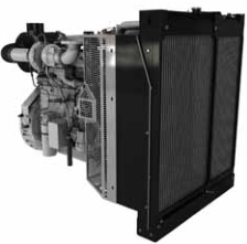
Engine Design
i04266651
Fuel Transfer Pump
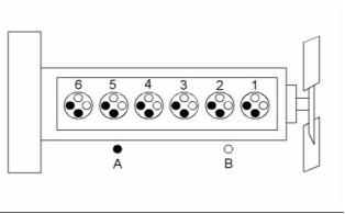
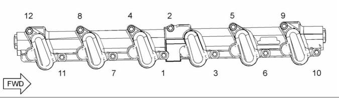
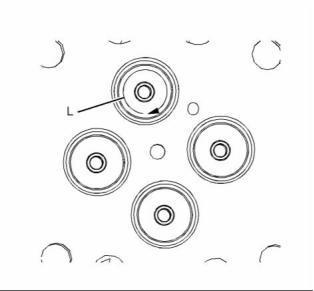
g01284058
Illustration 1
Cylinder and valve location
(A) Exhaust valve
(B) Inlet valve
Bore ........................................... 116.6 mm (4.6 inch)
Stroke ........................................ 146 mm (5.75 inch)
Displacement .......................... 9.3 L (570 cubic inch)
Cylinder arrangement ..................................... In-line
Type of combustion ............................ Direct injection
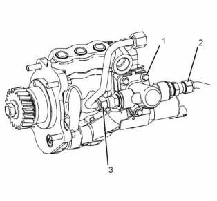
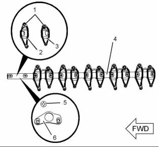
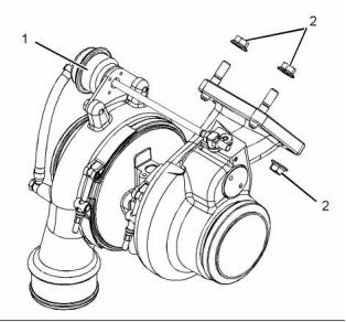
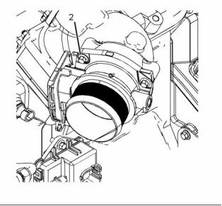
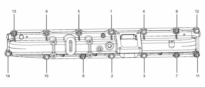
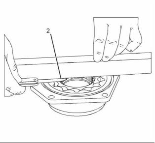
g02436061
Illustration 2
Typical example
(1) Tighten the bolts to the following torque. .. 16 N·m
(12 lb ft)
Compression ratio
(2), (3) Tighten the nuts to the following
torque. ...................................... 18 N·m (13 lb ft)
Turbocharged aftercooled ......................... 17.2:1
Number of cylinders ................................................ 6
Valves per cylinder .................................................. 4
Valve lash
Inlet valve ......................... 0.48 mm (0.019 inch)
Exhaust valve ................... 0.48 mm (0.019 inch)
Firing order ......................................... 1, 5, 3, 6, 2, 4
When the crankshaft is viewed from the front of
the engine, the crankshaft rotates in the following
direction: ................................................... Clockwise
When the camshaft is viewed from the front of
the engine, the camshaft rotates in the following
direction: ..................................... Counter Clockwise
This document is printed from SPI². Not for RESALE
![]()
![]()
![]()
KENR8771
5
Specifications Section
i04266409
Fuel Filter Base
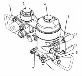
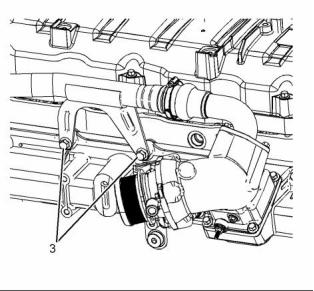
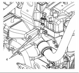
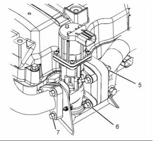
g02436178
Illustration 3
Typical example
(1) Tighten the nut to the following torque. .... 18 N·m
(13 lb ft)
(2) Tighten the strainer lid to the following
torque. ...................................... 18 N·m (13 lb ft)
(3) Tighten the fuel filter cap to the following
torque. ...................................... 30 N·m (22 lb ft)
(4) Tighten the fasteners to the following
torque. ...................................... 27 N·m (20 lb ft)
(5) Tighten the engine fuel pressure sensor to the
following torque. ....................... 11 N·m (97 lb in)
(6) Tighten the setscrews for the drain valve to the
following torque. ......................... 6 N·m (53 lb in)
(7) Tighten the water in fuel sensor to the following
torque. ........................................ 2 N·m (18 lb in)
Tighten the setscrews for the fuel heater (if equipped)
to the following torque. .................... 10 N·m (89 lb in)
This document is printed from SPI². Not for RESALE
![]()
![]()
6
KENR8771
Specifications Section
i04270145
Unit Injector Actuation Oil
Manifold
g02440077
i04270143
Illustration 4
Typical example
Tighten the bolts in the sequence shown in illustration
4 to the following torque. ................. 30 N·m (22 lb ft)
Unit Injector Hydraulic Pump
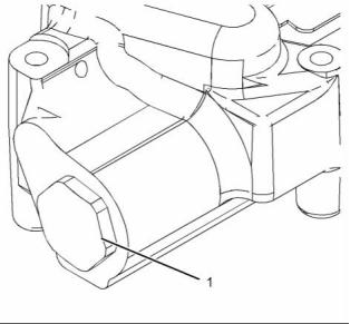
g02440176
Illustration 5
Typical example
(1) Tighten the plug to the following
torque. .................................. 204 N·m (150 lb ft)
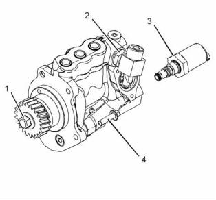
g02440276
Illustration 6
Typical example
(1) Tighten the bolt to the following torque. .. 240 N·m
(177 lb ft)
(2) Tighten the nut to the following torque. .. 102 N·m
(75 lb ft)
This document is printed from SPI². Not for RESALE
![]()
![]()
![]()
![]()
KENR8771
7
Specifications Section
Note: Apply two beads of Loctite 246 Threadlocker
i04232196
to the threads of the high-pressure oil elbows.
Rocker Shaft
(3) Tighten the Injection Pressure Regulator (IPR)
valve to the following torque. .... 50 N·m (37 lb ft)
(4) Tighten the bolts to the following torque. .. 30 N·m
(22 lb ft)
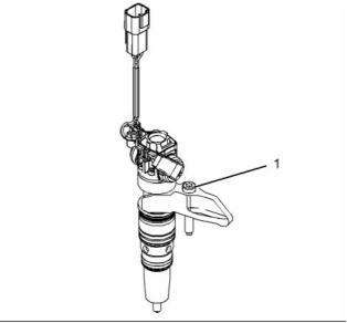
i04063369
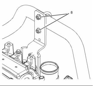
Electronic Unit Injector
g02407936
Illustration 8
Typical example
(1) Tighten the locknut to the following
torque. ...................................... 27 N·m (20 lb ft)
(2) Inlet rocker arm
Diameter of the rocker arm
bore ............................. 28.76804 ± 0.01270 mm
(1.13260 ± 0.00050 inch)
g02277093
Illustration 7
Typical example
(3) Exhaust rocker arm
(1) Tighten the bolt to the following torque. ... 30 N·m
(22 lb ft)
Diameter of the rocker arm bore
..................................... 28.76804 ± 0.01270 mm
(1.1326 ± 0.0005 inch)
This document is printed from SPI². Not for RESALE
![]()
![]()
![]()
8
KENR8771
Specifications Section
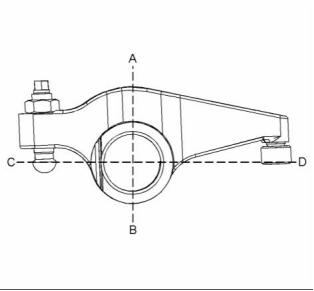
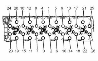
g02409356
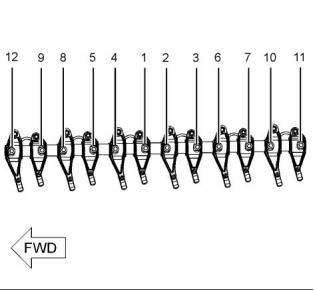
g02407837
Illustration 9
Illustration 10
Typical example
Tightening sequence
Use a telescoping gauge and outside micrometer to
measure rocker arm bore diameter at two locations.
Measure diameter at (A) to (B) and (C) to (D). If the
difference between diameters is greater than or equal
to 0.03 mm (0.0012 inch), replace the rocker arm.
Tighten the fasteners in the sequence that is in
illustration 10. Tighten the fasteners to an initial
torque. ............................................. 27 N·m (20 lb ft)
Tighten the fasteners in the sequence that is in
illustration 10. Tighten the fasteners to a final
torque. ............................................. 37 N·m (27 lb ft)
Clearance
Maximum clearance of both the rocker arm
bores. .............................. 0.127 mm (0.005 inch)
The service limit for both rocker arm
i04234947
Valve Mechanism
bores ............................. 0.0254 mm (0.001 inch)
(4) Rocker shaft
Diameter of the rocker
shaft ............................. 28.66644 ± 0.01270 mm
(1.12860 ± 0.00050 inch)
(5) Locator
(6) Pedestal
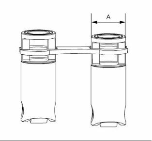
g02409503
Illustration 11
Typical example
This document is printed from SPI². Not for RESALE
![]()
![]()
![]()
![]()
KENR8771
9
Specifications Section
(A) Diameter of the lifter body .. 28.435 to 28.448 mm
(1.11949 to 1.12000 inch)
i04063712
Cylinder Head Valves
Bore diameter in the cylinder
block .................................... 28.5306 ± 0.01905 mm
(1.12325 ± 0.00075 inch)
Clearance
Clearance of the lifter ............ 0.064 to 0.115 mm
(0.00252 to 0.00453 inch)
Maximum runout of the push rod .............. 0.508 mm
(0.020 inch)
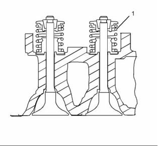
i03945459
Valve Mechanism Cover
g01333841
Illustration 13
Typical example
The same valve spring (1) is used on both valves.
When the valve springs are replaced the valve
springs must be replaced in pairs.
Free length of the valve spring ................. 52.35 mm
(2.061 inch)
Maximum solid height ........... 27.46 mm (1.081 inch)
Refer to table 1 for information on the length of the
valve spring and the load of the valve spring.
g02275713
Illustration 12
Table 1
Typical example
The load for the valve
spring
The length of the valve
spring
(1) Tighten the fasteners to the following
torque. .................................... 31 N·m (223 lb ft)
410.1 ± 24.5 N
40 mm (1.575 inch)
(92.19458 ± 5.50785 lb)
764.2 ± 48.9 N
29.3 mm (1.155 inch)
(171.79980 ± 10.99321 lb)
This document is printed from SPI². Not for RESALE
![]()
![]()
![]()

10
KENR8771
Specifications Section
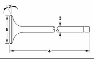
i04065669
Cylinder Head
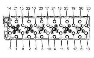
g01333842
Illustration 14
Typical example
(2) Valve face angle
Inlet ..................................... 59.75 to 60 degrees
Exhaust ............................... 44.75 to 45 degrees
g02278873
Illustration 15
Minimum valve face margin
Typical example
Inlet ................................... 1.32 mm (0.052 inch)
Exhaust ............................. 1.16 mm (0.046 inch)
Tighten the bolts in the sequence that is shown in
illustration 15 to an initial torque. .. 150 N·m (110 lb ft)
Maximum valve face-to-valve stem
runout .................................. 0.038 mm (0.0015 inch)
Tighten the bolts in the sequence that is shown in
illustration 15 to a second torque. ................ 238 N·m
(175 lb ft)
(3) Valve stem diameter
Inlet .................................. 7.92861 ± 0.0089 mm
(0.31215 ± 0.00035 inch)
Exhaust .............................. 7.9083 ± 0.0089 mm
(0.31135 ± 0.00035 inch)
Maximum valve stem straightness ............ 0.010 mm
(0.0004 inch)
Clearance
Maximum clearance of the inlet valve
stem .............................. 0.010 mm (0.0004 inch)
Maximum clearance of the exhaust valve
stem ................................... 0.11 mm (0.005 inch)
g02278874
Illustration 16
(4) Length of valve
Typical example
Inlet valve ............................ 145.44 ± 0.203 mm
(5.726 ± 0.008 inch)
Exhaust valve .................... 145.060 ± 0.203 mm
(5.711 ± 0.008 inch)
Tighten the bolts in the sequence that is shown in
illustration 16 to the following torque. .......... 238 N·m
(175 lb ft)
Tighten the bolts in the sequence that is shown in
illustration 15 to the additional amount. .. 90 degrees
(5) Valve head
Diameter of inlet valve head .... 39.73 ± 0.13 mm
(1.56417 ± 0.00512 inch)
Diameter of exhaust valve
Minimum thickness of cylinder head ....... 159.97 mm
(6.298 inch)
head ......................................... 36.55 ± 0.13 mm
(1.43897 ± 0.00512 inch)
This document is printed from SPI². Not for RESALE
![]()
![]()
![]()
![]()
KENR8771
11
Specifications Section
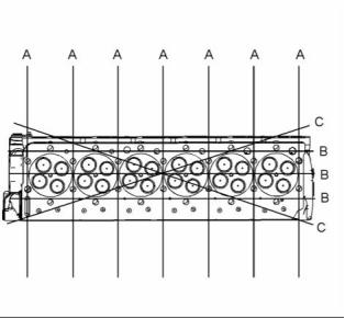
g02278893
Illustration 17
Typical example
Note: The maximum distortion of the cylinder head
is given in table 2.
Table 2
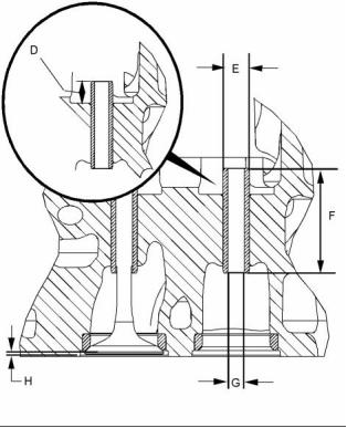
g02328933
Illustration 18
Maximum Permissible
Dimension
Distortion
Typical example
(D) Valve guide height from the top of the valve guide
to the valve spring seat ............ 16.54 ± 0.25 mm
(0.65118 ± 0.00984 inch)
Width (A)
Length (B)
0.10 mm (0.004 inch)
0.10 mm (0.004 inch)
0.10 mm (0.004 inch)
Diagonal Line (C)
(E) Outside diameter of the valve
guides .................................. 14.351 ± 0.010 mm
(0.56500 ± 0.00039 inch)
(F) Length of the valve guides ................. 65.71 mm
(2.587 inch)
(G) Internal diameter of the installed valve
guides ....................................... 7.98 to 8.00 mm
(0.31417 to 0.31496 inch)
The maximum wear limit for the internal diameter of
the installed valve guides
Inlet ................................. 0.102 mm (0.004 inch)
Exhaust ........................... 0.127 mm (0.005 inch)
(H) Valve depths
Inlet ........... 1.02 ± 0.13 mm (0.040 ± 0.005 inch)
The service limit for the depth of the inlet valve
...................................... 1.15 mm (0.04528 inch)
Exhaust ..... 1.40 ± 0.13 mm (0.055 ± 0.005 inch)
The service limit for the exhaust valve
depth ............................. 1.53 mm (0.06024 inch)
This document is printed from SPI². Not for RESALE
![]()
![]()

![]()
12
KENR8771
Specifications Section
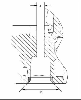
(L) Concentricity of valve seat to valve guide
parent bore Maximum Total Indicated Reading
(TIR) ............................... 0.076 mm (0.003 inch)
i03945797
Turbocharger
g02474819
Illustration 19
Typical example
(J) Diameter of the parent bore in the cylinder
head ..................................... 14.308 ± 0.017 mm
(0.56331 ± 0.00067 inch)
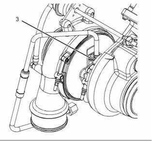
g02276955
Illustration 21
Typical example
(K) Seat angle
(1) Actuator
Inlet ..................................... 59.76 to 60 degrees
Exhaust ............................... 44.75 to 45 degrees
The test pressure for the wastegate
actuator ..................................... 334 kPa (48 psi)
The movement for the rod
actuator ..................................... 0.76 to 0.94 mm
(0.02992 to 0.03701 inch)
(2) Tighten the nuts to the following torque. .. 71 N·m
(52 lb ft)
g02962056
Illustration 20
Typical example
This document is printed from SPI². Not for RESALE
![]()
![]()
![]()
![]()
KENR8771
13
Specifications Section
g02276994
g02409756
Illustration 22
Illustration 24
Typical example
Typical example
(3) Tighten the bolt to the following torque. ... 13 N·m
(115 lb in)
(2) Tighten the bolts to the following torque. .. 13 N·m
(115 lb in)
i04235122
Exhaust Gas Valve (NRS)
(If Equipped)
g02409801
Illustration 25
Typical example
(3) Tighten the bolts to the following torque. .. 62 N·m
(46 lb ft)
g02409696
Illustration 23
Typical example
(1) Tighten the bolts to the following torque. .. 31 N·m
(23 lb ft)
This document is printed from SPI². Not for RESALE
![]()
![]()
![]()
![]()
![]()
14
KENR8771
Specifications Section
g02409858
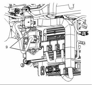
g02439618
Illustration 26
Illustration 28
Typical example
Typical example
(4) Tighten the bolts to the following torque. .. 31 N·m
(23 lb ft)
(8) Tighten the nuts to the following torque. .. 23 N·m
(17 lb ft)
g02438296
g02439636
Illustration 27
Illustration 29
Typical example
Typical example
(5) Tighten the nuts to the following torque. .. 31 N·m
(23 lb ft)
(9) Tighten the bolts to the following torque. .. 13 N·m
(115 lb in)
(6), (7) Tighten the bolts to the following
torque. ...................................... 23 N·m (17 lb ft)
This document is printed from SPI². Not for RESALE
![]()
![]()
![]()
![]()
![]()
KENR8771
15
Specifications Section
i04235093
Exhaust Cooler (NRS)
(If Equipped)
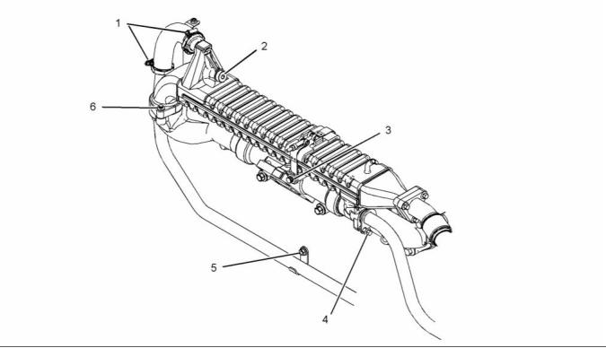
g02409938
Illustration 30
Typical example
(1) Tighten the clamps to the following
torque. ..................................... 3.3 N·m (29 lb in)
(2) Tighten the plug to the following torque. .. 62 N·m
(46 lb ft)
(3) Tighten the bolt to the following torque. .. 116 N·m
(86 lb ft)
(4) Tighten the bolt to the following torque. ... 31 N·m
(23 lb ft)
(5) Tighten the nuts to the following torque. .. 31 N·m
(23 lb ft)
(6) Tighten the bolts to the following torque. .. 31 N·m
(23 lb ft)
This document is printed from SPI². Not for RESALE
![]()
![]()
16
KENR8771
Specifications Section
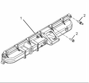
i04215509
Inlet Manifold
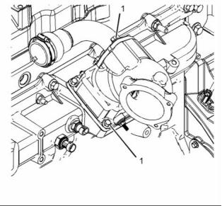
g02395397
Illustration 31
Typical example
(1) Inlet manifold
g02942740
Illustration 32
Typical example
(2) Tighten the fasteners in the sequence in
illustration 32 to the following torque. ...... 62 N·m
(46 lb ft)
This document is printed from SPI². Not for RESALE
![]()
![]()
![]()
KENR8771
17
Specifications Section
i03945471
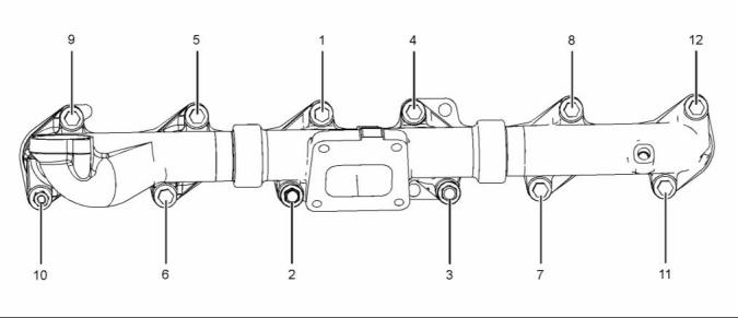
Exhaust Manifold
g02275835
Illustration 33
Typical example
Tighten the fasteners in the sequence shown in
illustration 33 to an initial torque. .... 27 N·m (20 lb ft)
Tighten the fasteners in the sequence shown in
illustration 33 to second torque. ...... 54 N·m (40 lb ft)
Tighten the fasteners in the sequence shown in
illustration 33 to a third torque. ..... 109 N·m (80 lb ft)
Note: On 1606D engines, fastener (4) should be
tightened to a final torque of 116 N·m (85 lb ft).
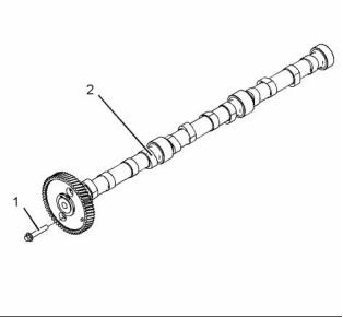
i04068907
Camshaft
End play of a camshaft ................... 0.18 to 0.33 mm
(0.00709 to 0.01299 inch)
g02280533
Illustration 34
Typical example
(1) Camshaft thrust plate bolts ....... 31 N·m (23 lb ft)
(2) Camshaft journals diameter .. 57.96 to 57.99 mm
(2.28189 to 2.28307 inch)
Camshaft inlet lobe lift ........ 6.68 mm (0.26299 inch)
Camshaft exhaust lobe lift .. 6.91 mm (0.27205 inch)
This document is printed from SPI². Not for RESALE
![]()
![]()
![]()
18
KENR8771
Specifications Section
Maximum wear on the camshaft lobes ....... 0.25 mm
(0.010 inch)
i04070869
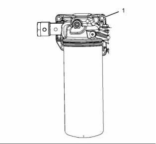
Engine Oil Filter Base
Thrust plate thickness ..................... 6.96 to 7.01 mm
(0.274 to 0.276 inch)
Check the camshaft lobes for visible damage. If a
new camshaft is installed, install new lifters.
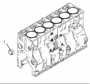
i04234456
Camshaft Bearings
g02281113
Illustration 36
Typical example
(1) Tighten the fasteners to the following
torque. ...................................... 31 N·m (23 lb ft)
g02409436
Illustration 35
Typical example
(1) The diameter of the installed camshaft
bearing .................................. 58.04 to 58.12 mm
(2.285 to 2.288 inch)
This document is printed from SPI². Not for RESALE
![]()
![]()
![]()
KENR8771
19
Specifications Section
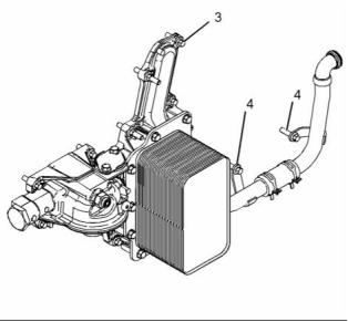
i04215532
(4) Tighten the bolts to the following torque. .. 31 N·m
(23 lb ft)
Engine Oil Cooler
i04195171
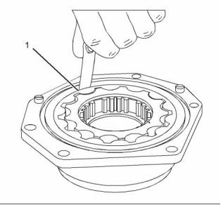
Engine Oil Pump
Type ................... Spline gear-driven differential rotor
Number of lobes
Inner rotor ......................................................... 4
Outer rotor ........................................................ 5
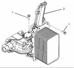
g02395398
Illustration 37
Typical example
(2) Engine oil cooler
(1) Tighten the setscrews to the following
torque. ...................................... 31 N·m (23 lb ft)
g02384821
Illustration 39
Typical example
(1) Clearance of the outer rotor to the
body ........ 0.05 to 0.13 mm (0.002 to 0.005 inch)
g02395400
Illustration 38
Typical example
(3) Tighten the fasteners to the following
torque. ...................................... 31 N·m (23 lb ft)
This document is printed from SPI². Not for RESALE
![]()
![]()
![]()
![]()
20
KENR8771
Specifications Section
g02384824
Illustration 40
Typical example
(2) End play of rotor assembly ....... 0.48 to 0.62 mm
(0.019 to 0.024 inch)
g02384878
Illustration 41
Typical example
(3), (4) Tighten the bolts to the following
torque. ...................................... 25 N·m (18 lb ft)
This document is printed from SPI². Not for RESALE
![]()
![]()
![]()
KENR8771
21
Specifications Section
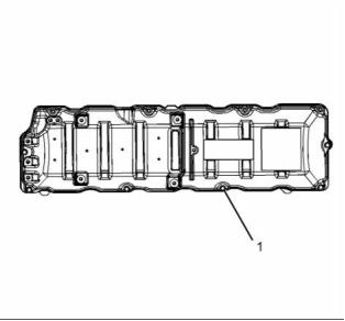
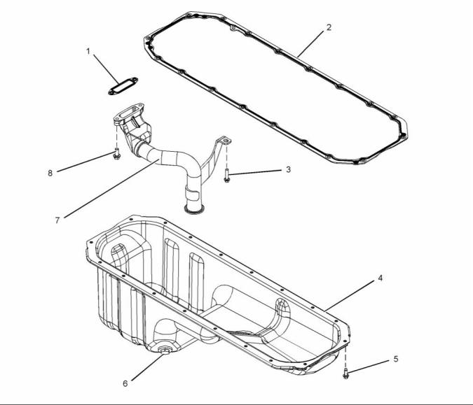
i04193209
Engine Oil Pan
g02383105
Illustration 42
Typical example
(1) Gasket
(2) Gasket
(4) Oil pan
(7) Oil suction tube assembly
This document is printed from SPI². Not for RESALE
![]()
![]()
22
KENR8771
Specifications Section
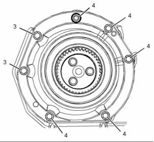
g02441976
Illustration 43
Typical example
Tighten the bolts in the sequence that is shown in
illustration 43 to the following torque. .......... 122 N·m
(90 lb ft)
g02442076
Illustration 44
Tighten the bolts in the sequence that is shown in
illustration 44 to the following torque. ............ 63 N·m
(46 lb ft)
(3) Tighten the bolt to the following torque. ... 62 N·m
(46 lb ft)
(5) Tighten the bolts to the following torque. .. 32 N·m
(24 lb ft)
(6) Tighten the oil drain plug to the following
torque. ...................................... 68 N·m (50 lb ft)
(8) Tighten the bolts to the following torque. .. 27 N·m
(20 lb ft)
Tighten the heater plug for the engine oil pan (if
equipped) to the following torque. ... 68 N·m (50 lb ft)
This document is printed from SPI². Not for RESALE
免费热线
400-100-8969 15088860848
400-100-8969 15088860848
机组销售
0574-26871589 15267810868
0574-26871589 15267810868
配件销售
0574-26886646 15706865167
0574-26886646 15706865167
维修热线
0574-26871569 18658287286
0574-26871569 18658287286
手机端

微信公众号