 English
 Espaol
 Franais
 阿拉伯
阿拉伯 中文(简)
中文(简) Deutsch
 Italiano
 Português
 日本
日本 韩国
韩国 български
 hrvatski
 esky
esky Dansk
Dansk Nederlands
 suomi
suomi Ελληνικ
 印度
印度 norsk
norsk Polski
 Roman
Roman русский
 Svenska
 珀金斯Perkins2000燃气机用户手册,珀金斯Perkins2000燃气机用户手册技术支持中心,珀金斯Perkins2000燃气机用户手册代理商,珀金斯Perkins2000燃气机用户手册销售服务中心,珀金斯Perkins2000燃气机用户手册价格规格资料查询,宁波日昕动力科技有限公司

珀金斯Perkins2000燃气机用户手册
详细描述
Perkins 2000 Series
Models 2006SI and 2006TSI
USER’S HANDBOOK
6 cylinder spark ignited engines for industrial
applications
chedule for turbocharged engines in intermittent use
The preventive maintenance operations must be applied at the interval (hours or months) which occurs first.
A - Monthly
B - Every 200 hours or 12 months
A
z
z
z
z
z
z
B
Operation
Check the amount of coolant in the radiator
Check the level of the lubricating oil in the sump
Check the gas supply pressure
Start and run the engine until normal operating temperature is attained
Check the lubricating oil pressure at the gauge (2)
Check the restriction indicator for the air filter. Renew the filter element if the indicator shows red
z
z
z
z
z
z
z
z
z
z
Check the condition of the high tension leads
Check the condition and tension of all drive belts (2)
Check the specific gravity and the pH value of the coolant
Renew the lubricating oil (3)
Renew the canisters of the lubricating oil filter and the rotor of the by-pass filter (2)
Check that the radiator is clean and free from debris (2)
Check and reset or change the spark plugs
Renew crankcase ventilator filter and clean crankcase breather
Ensure the mounting nuts for the turbocharger are tightened securely (1)
Ensure that the tappet setting clearances are checked and adjusted if it is necessary (1)(4)
(1) By a person who has had the correct training.
(2) If fitted.
(3) The selection of suitable lubricants should be made in co-operation with a reputable oil company, who can offer the necessary oil
sample analysis support to ensure successful lubrication of spark ignited engines. Analysis results will determine the service period
which could be less than the 500 hour service period. Refer to Chapter 5, Engine systems for details.
(4) After the first 500 hours on a new and overhauled engine.
In addition to the above, the operations shown below must be applied at 12 month intervals:
z Drain and flush the coolant system and renew the coolant mixture.
z Ensure the control linkages for the carburettor are free to move and are lubricated.
z Change the air filter element.
z Ensure that the alternator, starter motor, turbocharger and protection switches are checked or serviced as
(1)
.
necessary
User’s Handbook, TSD 3409, Issue 4
19
This document has been printed from SPI². Not for Resale
![]()
![]()

4
2000 Series Gas
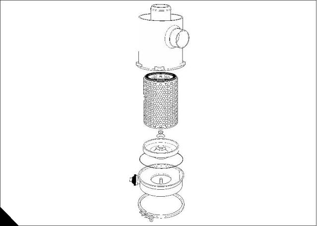
Air filter
The air filter (A) is a dry type unit fitted with a restriction indicator and rain hood.
Servicing
To obtain the best performance from the air filter, it should be serviced when indicated, as determined by the
restriction indicator. Over servicing does not take full advantage of the features of the air filter and may cause
damage.
How to service the air filter
1 Slacken the clamp ring and remove the dust bowl and baffle assembly. Remove the wing nut and separate
the bowl and baffle.
2 Empty the bowl, clean both components and reassemble.
3 Unscrew the element securing nut and carefully withdraw the element.
2
2
4 Direct a jet of compressed air, maximum pressure of 700 kN/m (100 lbf/in ), up and down the inside of the
element pleats.
Caution: Do not hold the jet nozzle close to the element.
5 Inspect the element for damage by placing a lighted bulb inside. Thin areas or perforations indicate that the
element must be renewed immediately.
6 Clean the air filter body, refit the element and dust bowl assembly and tighten the clamp ring.
7 Reset the restriction indicator.
Note: An alternative method of cleaning the element is to soak it in a solution of detergent, following the
instructions on the packet. For recommended detergent contact Perkins Engines Company Limited.
A
20
User’s Handbook, TSD 3409, Issue 4
This document has been printed from SPI². Not for Resale
![]()
![]()
4
2000 Series Gas
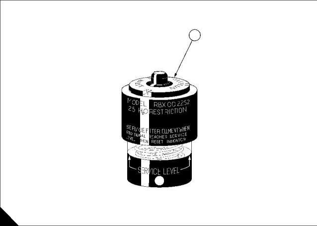
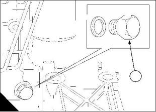
Restriction indicator
An indicator (A1) is fitted to the air cleaner to give visual warning of the fouling of the element.
As fouling increases, a red sleeve gradually moves into view in the indicator sight glass. At the limit of the
fouling the sleeve will reach the service level and remain there when the engine is shut down. This indicates
that the air filter must be serviced immediately.
If during engine operation the sleeve shows partial restriction there is no immediate necessity to service the
air filter. It is however advisable to service the air filter at normal shutdown.
Press the button in the end of the indicator to reset.
1
A
User’s Handbook, TSD 3409, Issue 4
21
This document has been printed from SPI². Not for Resale
![]()
![]()
4
2000 Series Gas
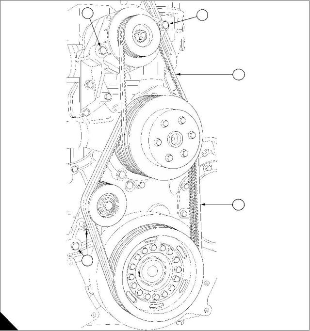
How to check the drive belts
Check all drive belts and renew a belt if it is worn or damaged. Where more than one belt is used between two
pulleys, all of the belts must be renewed together. Do not fit an individual belt except where only one belt is
fitted as standard.
It is recommended that a bolt tensioner gauge, fitted at the centre of the longest free length (A1) is used to
check the belt tension.
1
The correct belt deflection at this point should be 12 mm ( / in) under the following pressures:
2
Fan belts
z 254 mm (10 in) pulley centres: 6,3 to 7,25 kgf (14 to 16 lbf).
z 321 mm (12.625 in) pulley centres: 5 to 6 kgf (11 to 13 lbf).
Alternator belt
z All engines: 6,5 to 7,5 kgf (14.5 to 16.5 lbf).
3
3
1
1
2
A
22
User’s Handbook, TSD 3409, Issue 4
This document has been printed from SPI². Not for Resale
![]()
![]()

4
2000 Series Gas
How to adjust the drive belts
Coolant pump drive belts (where fitted)
Slacken the belt tensioner securing and clamping bolts (A2); slide the tensioner until the correct belt tension is
obtained (see "How to check the drive belts" on page 22) and tighten the two bolts.
Alternator belt (where fitted)
Slacken the fixing and adjusting bolts (A3) and position the alternator to obtain the correct belt tension (see
"How to check the drive belts" on page 22). Tighten the two bolts.
Re-check the belts to ensure that the tension is still correct.
Note: Maximum life and efficiency of the belt will only be obtained if they are maintained at the correct tension.
3
3
1
1
2
A
User’s Handbook, TSD 3409, Issue 4
23
This document has been printed from SPI². Not for Resale
![]()
![]()
4
2000 Series Gas
How to check the specific gravity of the coolant
Drain some coolant from the cooling system after the engine has been stopped and before the formation of
sediment. Proceed as follows:
For mixtures which contain inhibited ethylene glycol:
1 Put a hydrometer, and a reliable thermometer, into the antifreeze mixture and check the readings on both
instruments.
2 Compare the readings obtained with the chart and adjust the strength of the mixture as necessary.
For mixtures which contain inhibited propylene glycol:
1 Open the cover of the refractometer, check that the clear panel is clean and use a small syringe to apply a
few drops of the coolant mixture to the clear panel.
2 Spread the coolant over the full area of the clear panel and close the cover. Hold the refractometer horizontal
with the clear panel up and inspect the sample through the viewer.
3 Compare the reading with the chart in the instructions; adjust the strength of the mixture as necessary.
Caution: The clear panel must be cleaned thoroughly before use. If some of the fluid which was tested earlier
remains on the clear panel, the reading of the sample will be affected.
Protection against frost is as follows:
Antifreeze/water
(% by volume)
Protection down to
(°C)
50/50
06/40
-35
-40
A
40
45 50 55 60
60
50
40
30
20
10
140
122
104
C
D
86
68
50
0
1.04
1.05
1.06
1.07
1.08
1.09
1.10 1.11
B
Specific gravity chart
A = Percentage anti-freeze by volume
B = Specific gravity
C = Mixture temperature in Centigrade
D = Mixture temperature in Fahrenheit
A
24
User’s Handbook, TSD 3409, Issue 4
This document has been printed from SPI². Not for Resale
![]()
![]()


4
2000 Series Gas
How to check the pH value of the coolant
The pH value of the coolant must not be less than pH7 or more than pH9.5. The pH value can be found by the
use of a pH meter or test papers, which are available from pharmaceutical manufacturers.
If these limits are exceeded the pH value may be adjusted by the addition of a corrosion inhibitor to the same
specification as that already in use. If this is not possible, the system must be drained, flushed and filled with
new coolant.
User’s Handbook, TSD 3409, Issue 4
25
This document has been printed from SPI². Not for Resale
![]()
![]()
4
2000 Series Gas
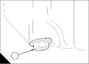
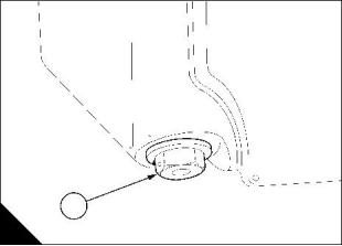
How to renew the engine lubricating oil
Ensure that the engine is on level ground.
1 Whilst the engine is warm remove the drain plug (A1, B1, C1, C2 or D1) and drain into a suitable container.
Caution: A thread insert is fitted to certain sumps. Inspect the thread to find which type is fitted to your engine.
2 Fit the drain plug and a new sealing washer and, according to the type of thread, proceed as follows:
7
1
Sump with a thread insert (A): This plug has a / UNS thread. Use a spanner - size 1 / AF - to tighten the
8
8
drain plug (A1) to a torque of 115 Nm (85 lbf ft). Retain the drain plug with locking wire if it is possible.
5
13
Sump without a thread insert (B): This plug has a / BSP thread. Use a spanner – size / AF - to tighten
8
16
the drain plug (B1) to a torque of 47,5 Nm (35 lbf ft). Retain the drain plug with locking wire if it is possible.
3
Note: The drain plugs of engines manufactured from build line number 95200 have a / BSP thread.
4
1
1
A
B
3
15
16
Sump without a thread insert (C): These plugs have a / BSP thread. Use a spanner - size / AF - to
4
tighten the drain plug (C1 or C2) to a torque of 61 Nm (45 lbf ft).
Plastic composite sump (D): These engines are fitted with a plug which has a 19 mm socket. For some
1
applications the plug may have a / inch square recess. Tighten the sump plug by use of a 19 mm socket
2
1
spanner or a / inch extension bar from a set of socket spanners as necessary. Tighten the plug (D1) to a
2
torque of 61 Nm (45 lbf ft).
Caution: Overtightening of the drain plug may result in damage to the threads in the sump. It is permissible to
5
repair the thread in sump (B) by use of a / inch BSP Helicoil insert.
8
1
1
2
C
D
Continued
26
User’s Handbook, TSD 3409, Issue 4
This document has been printed from SPI². Not for Resale
![]()
![]()
4
2000 Series Gas
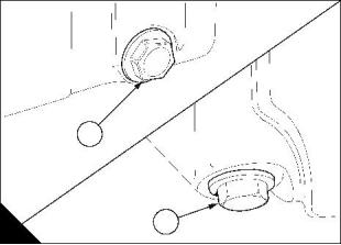
Ensure that the engine is on level ground.
3 Renew both of the oil filter canisters, see "How to renew the canisters of the oil filter" on page 28.
4 Clean the area around the oil filler cap and remove the cap.
5 Use a clean container and funnel and fill the engine to the H mark on the dipstick (E1 or F1) with a
recommended grade of oil, see "Lubricating oil specification" on page 40.
Caution: Do not overfill.
6 Operate the engine and check for leakage from the filter canisters. When the engine has cooled, check the
level on the dipstick and put more oil into the sump if necessary.
1
1
F
E
User’s Handbook, TSD 3409, Issue 4
27
This document has been printed from SPI². Not for Resale
![]()
![]()
4
2000 Series Gas
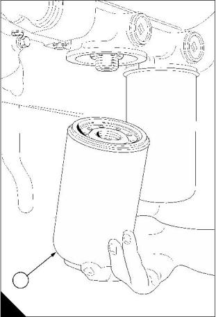
How to renew the canisters of the oil filter
Twin expendable oil filter canisters are fitted to the filter header bracket which is an integral part of the heat
exchanger casing, mounted at the front right side of the engine.
1 Place a tray under the filters and unscrew each canister in turn using strap wrench 21825 825.
2 Check that the seal rings are correctly fitted (A1) on the new canisters and clean the filter header bracket
contact faces.
3 Fill two new canisters with a clean approved grade of lubricating oil and apply a light smear to the sealing
ring.
4 Screw each canister into position until the sealing rings contact the face of the header and then a further
1
1 / turns by hand.
4
Caution: Do not overtighten.
Note: A non-adjustable valve fitted in the base of each canister allows unfiltered oil to circulate through the
2
2
engine if a canister becomes choked and the pressure drop across it exceeds 102,96 kN/m (15 lbf/in ).
1
A
28
User’s Handbook, TSD 3409, Issue 4
This document has been printed from SPI². Not for Resale
![]()
![]()
4
2000 Series Gas
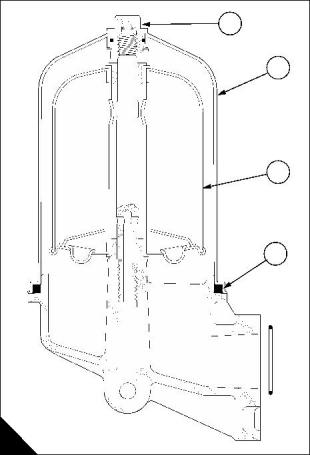
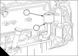
Lubricating oil by-pass filter
Description
Some engines are fitted with a by-pass filter. It is not an alternative. The filter must be serviced at the intervals
specified for engine oils and main filter changes.
To dismantle
1 Clean off any dirt or debris from the area surrounding the filter.
2 Unscrew the filter bowl (A2), remove and discard the rotor (A3).
3 Remove the square section rubber ring (A4) from the filter bowl or housing.
To assemble
1 Clean all components.
2 Clean the seal recess in the bowl and wipe clean the seal face on the housing.
3 Fit a new rubber seal over the seal face of the housing and apply a light smear of oil to the face of the seal.
4 Assemble a new rotor to the spindle and check that it spins freely.
5 Fit the bowl and tighten the securing nut (A1) to a torque loading of 20 Nm (15 lbf ft).
6 When the engine is started, check the filter for leaks and rectify if necessary
1
2
3
4
A
User’s Handbook, TSD 3409, Issue 4
29
This document has been printed from SPI². Not for Resale
![]()
![]()
4
2000 Series Gas
How to change the spark plugs
1 Disconnect the spark plug leads and note the position of each to ensure that they are refitted to the correct
location.
2 Remove the spark plug extension (A1), unscrew the spark plug using the spanner provided or a 14 mm spark
plug socket spanner of no more than 26 mm outside diameter. Clean or renew the spark plugs and set the
spark plug gap to 0,30 mm (0.012 in).
3 Fit the spark plugs and tighten to a torque of 30 Nm (22 lbf ft) or finger-tight and turn a further 90°.
4 Insert the spark plug extension (A1) and ensure that it is attached firmly to the spark plug terminal. The spark
plug extension forms part of the spark plug lead.
5 Check that the spark plug leads are fitted in the correct sequence.
Note: The spark plug leads have a core of copper and are not suppressed. Suppression is accomplished by
fitting a resistive spark plug and a resistor in the spark plug extension (A1). The spark plug extension and spark
plug leads must be renewed as a set.
1
A
30
User’s Handbook, TSD 3409, Issue 4
This document has been printed from SPI². Not for Resale
![]()
![]()

4
2000 Series Gas
How to renew the filter of the crankcase breather
1 Ensure that the area around the breather filter (A2) is clean.
2 Loosen the hose clip (A1), remove the air inlet filter (A2) and discard.
3 Ensure that the pipe is clean and is free from restrictions.
4 Fit carefully a new filter to the inlet pipe and tighten securely the hose clip (A1).
2
1
A
User’s Handbook, TSD 3409, Issue 4
31
This document has been printed from SPI². Not for Resale
![]()
![]()
4
2000 Series Gas
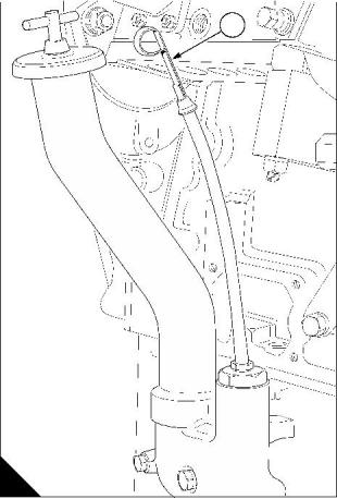
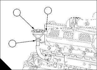
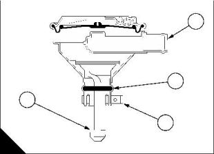
How to clean the crankcase breather control valve
The crankcase breather control valve (A2) is generally maintenance free. If the lubricating oil consumption is
high and also after an engine overhaul, the operation of the breather control valve must be checked and the
assembly cleaned or renewed if necessary. Use the procedure which follows:
1 Loosen the hose clips (A3) and slide the hose fully onto the manifold pipe. This will allow the control valve
to be moved vertically.
2 Push the rubber hose, on the valve-to-inlet manifold pipe, one way as far as it will go to allow the valve to
be removed vertically.
3 Loosen the clamp (A1).
4 Remove carefully the breather control valve from the pipe. Ensure that it is removed vertically and not tilted
in any direction.
5 Ensure that inlet and outlet pipes (B1 and B3) are clean and free from debris.
6 To clean a dirty breather control valve, wash thoroughly with diesel oil. Invert the ventilator valve and add
diesel oil to the opening (B3) until clean diesel oil flows from the opening (B1). Drain thoroughly the control
valve and leave for several hours to dry.
7 Examine visually the rubber ‘O’ ring (B2) for damage and renew if necessary.
8 Fill the oil pot (B4) with clean engine oil. Ensure that the control valve is kept upright and fit it carefully to its
pipe.
Note: Breather control valves on naturally aspirated engines do not have the oil pot (B4).
9 Align the outlet pipe (B1) with the pipe on the inlet manifold and tighten the clamp (A1).
10 Return the rubber hose to its original position to connect the control valve to the inlet manifold. Tighten the
hose clips (A3).
1
3
2
2
1
4
3
A
B
32
User’s Handbook, TSD 3409, Issue 4
This document has been printed from SPI². Not for Resale
![]()
![]()
4
2000 Series Gas
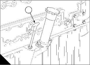
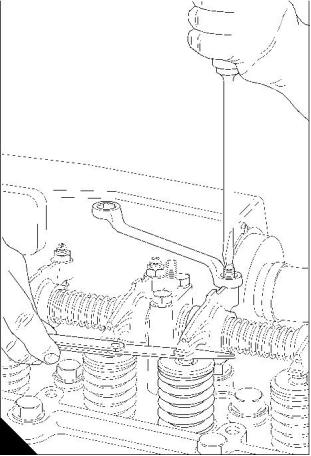
How to check the tappet clearances
The tappet clearance is measured between the rocker lever and the top of the valve stem.
The tappet clearances are measured between the rocker levers and the tips of the valves (A). Check and
adjust the tappet clearances in the sequence which follows, while the spark plugs are removed for service.
Valves rocking on cylinder No
Check tappets on cylinder No
6
3
5
1
4
2
1
4
2
6
3
5
Valves rocking means ‘inlet valve just opening’ and ‘exhaust valve just closing’.
1 Remove the engine rocker covers.
2 Turn the engine in the normal direction of rotation until the valves on number 6 cylinder are ‘rocking'. Check
and adjust the tappet clearances on number 1 cylinder to the correct clearance.
3 Continue to rotate the engine and adjust the remaining tappets in the sequence given above.
4 Refit the rocker covers.
Tappet clearances:
z Exhaust: 0,508 mm (0.020 in)
z Inlet: 0,254 mm (0.010
A
User’s Handbook, TSD 3409, Issue 4
33
This document has been printed from SPI². Not for Resale
![]()
![]()

4
2000 Series Gas
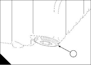
How to drain the cooling system
It is recommended that the system is drained as soon as possible after the engine is stopped and before any
deposits in the coolant have settled.
1 Ensure that the engine is on level ground.
2 Remove carefully the radiator filler cap, especially when the engine is hot.
Warning! Use care during the removal of the filler cap as the coolant system will be under pressure.
3 Remove the coolant drain plug (A1) from the rear of the left side of the engine. Ensure that the drain hole is
not restricted. Note that on some specifications there is an additional drain plug in the coolant pipe of the oil-
to-coolant heat exchanger.
4 To drain the radiator refer to the Equipment Manufacturer’s Instruction Manual.
5 Flush the system with clean water.
6 Fit a new sealing washer onto the drain plug. Replace the engine drain plug (in both the engine and the heat
exchanger pipe if fitted) and any items removed in accordance with the Instruction Manual as in step 4.
7 Affix a ‘coolant drained’ label in a prominent position if the engine is not to be refilled immediately.
1
A
34
User’s Handbook, TSD 3409, Issue 4
This document has been printed from SPI². Not for Resale
![]()
![]()
2000 Series Gas
5
Engine systems
5
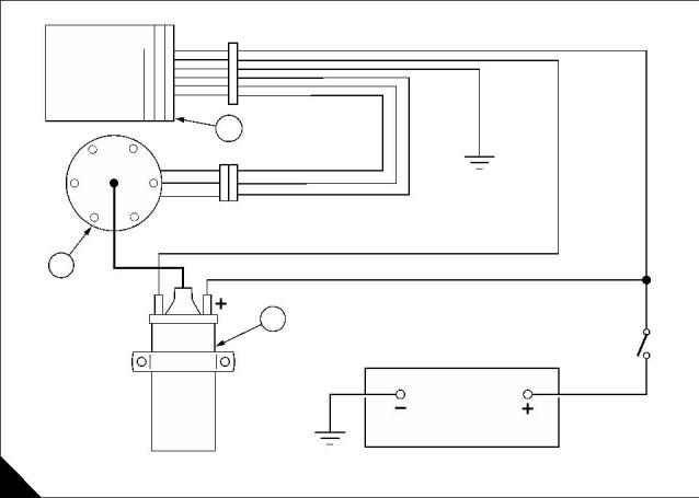
Ignition system - distributor type
The Perkins 2006SI naturally aspirated spark ignited engine utilises a 12 volt, contactless, electronic distributor
system. A Fairbanks Morse system is offered on later engines
The function of the distributor is to provide signals which are accurately timed relative to the position of the
engine crankshaft.
The signals are produced by a ‘Hall effect' vane switch through which passes a slotted rotor vane. The
distributor is driven at half engine speed and the number of slots on the rotor corresponds to the number of
engine cylinders.
When a slot in the rotor vane passes through the vane switch, a signal is produced. These signals are fed to
the amplifier/switching unit (A2) which by transistor action switches the supply to the low tension side of the
ignition coil (A3).
Distribution of the high tension output produced from the coil is through a conventional rotor arm which forms
the upper segment of the rotor vane.
WHITE
AB 13
AMPLIFIER
BLACK
2
BLACK
AND
WHITE
BLACK
GREEN
RED
1
3
SWITCH
12V
WIRING DIAGRAM FOR CONTACTLESS ELECTRONIC IGNITION
A
User’s Handbook, TSD 3409, Issue 4
35
This document has been printed from SPI². Not for Resale
![]()
![]()
5
2000 Series Gas
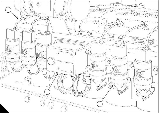
Ignition system - Fairbanks Morse type
The Perkins 2006TSI turbocharged, and later 2006SI naturally aspirated, spark ignited engine utilise a 24 volt
Fairbanks Morse ignition system.
Description
The 24 volt battery is the source of the electrical power; the system is controlled by the Ignition Control Module
(ICM)(A2).
Information is placed in the memory of the ICM by the engine manufacturer eg. the number of teeth on the
starter ring, the number of cylinders, the firing interval, the start of the engine cycle.
The teeth on the engine flywheel generate alternating current as they pass the sensor in the flywheel housing;
this current is transmitted to the ICM.
A sensor, sited at the timing case, senses the reluctor pin attached to the camshaft; the sensor is supplied with
24 volt DC and the reluctor pin completes the circuit as it passes the sensor and
the 24 volt current is returned to the ICM thus indicating the start of a new cycle.
The ICM processes the information and transmits precision timed voltage in correct sequence to each coil (A1).
The coil increases the electrical voltage and transmits it along the high tension leads (A3) to the appropriate
spark plug.
3
2
1
A
36
User’s Handbook, TSD 3409, Issue 4
This document has been printed from SPI². Not for Resale
![]()
![]()
5
2000 Series Gas
Fuel system
Introduction
To ensure safe and consistent operation of a gas powered spark ignited engine it is important to pay particular
attention to the fuel supply system. In some locations gas engine installations are subject to mandatory
requirements. Please discuss proposed installations with the appropriate authorities.
This chapter is intended as a guide to successful installation and cannot cover every possible hazard. It is the
responsibility of the installers to consider and avoid possible hazardous conditions at any given installation.
In general these recommendations are based on the ‘British Gas Code of Practice for Natural Gas Fuelled
Spark Ignition Engines’ - Publication IM/17. They will also apply to operation on other types of hydrocarbon
gaseous fuels, ie. landfill, biogas and well-head gases. With these latter gases there may be additional
requirements in terms of gas treatment, dual starting etc. which must be considered at the installation stage.
Standard equipment
In their basic form Perkins spark ignited engines will be supplied fitted with a carburettor, the zero pressure
regulator will be supplied but not fitted.
The purpose of the carburettor is to mix the fuel gas and air in the correct ratio and, in conjunction with the
governor, control the flow of the air/fuel mixture to the engine cylinders.
The ratio of air to gas mixed by the carburettor is determined by the difference in pressure of air and gas
supplied to the carburettor.
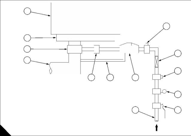
The air to gas pressure differential is maintained by the gas pressure regulator (A).
The function of the balance line on naturally aspirated engines is to allow the regulator to sense actual air inlet
pressure. This prevents variations in air to fuel ratio due to air filter restriction in service.
13
1
12
11
10
2
3
9
8
7
6
1
Shut-off solenoid valve
Flexible pipe
2
3
Shut-off solenoid valve
Gas supply low pressure detector
Manual shut-off valve
4
4
5
5
6
Gas supply - 200 to 500mm H O
2
7
Zero pressure regulator
Balance line
8
9
Mixture adjustment screw
Air in
10
11
12
13
Carburettor
Induction manifold
Engine
TYPICAL FUEL SYSTEM LAYOUT
A
User’s Handbook, TSD 3409, Issue 4
37
This document has been printed from SPI². Not for Resale
![]()
![]()
5
2000 Series Gas
Coolant
1 The coolant approved for use in all engines manufactured by PE(S)L is a mixture of 50% inhibited ethylene
glycol or 50% inhibited propylene glycol and 50% clean fresh ‘soft' water.
Mixtures containing methanol are not approved.
Anti-freeze mixtures supplied by most major chemical and oil companies are suitable, but the operator is
responsible for obtaining
the manufacturer's assurance that the ethylene glycol or propylene glycol products they supply have an
inhibitor performance level suitable for a multi-metal cooling system.
2 If anti-freeze is not available, and there is no likelihood of ambient temperatures below 10 °C, then clean
fresh ‘soft’ water may be used, treated with 1% by volume of PE(S)L inhibitor, in the cooling system. This
proportion is the equivalent of 0,5 litre of inhibitor to 50 litres or 11 UK gallons of water. The inhibitor is available
in bottles under Part No. OE 45350 (1,0 litre).
Caution: The use of any other product may cause serious problems in the cooling system, and the use of
insufficiently inhibited coolant mixtures may lead to erosion and/or corrosion of aluminium or cast iron
components in the system.
38
User’s Handbook, TSD 3409, Issue 4
This document has been printed from SPI². Not for Resale
![]()
![]()
5
2000 Series Gas
Condemnation levels for oil sample analysis
The following levels are intended as a guide for both operator and oil companies. In case of doubt, it should
always be remembered that a change of oil is a very cheap alternative to an engine failure.
Viscosity increase
Viscosity CSt at 100 °C
SAE grade
New oil
9.3 - 12.5
12.5 - 16.3
Used oil
14.4 max
19.0 max
30
40
Insolubles % wt 0.3 micron filter - 1% max
TBN and TAN - For used oil analysis the ASTM D664 gives the most meaningful results. When the TBN has
dropped to one third of the new oil value, the oil should be changed. When the TAN reading has increased to
the same level as the used oil TBN reading, the oil should be changed.
Oxidation and Nitration - assessed by infra-red analysis. Limits to be advised by the individual oil company.
Element
Water
Limit max ppm
5000
Comment
Above these limits indicates coolant leak into the engine. Source of
leak needs to be rectified and the oil changed
Glycol, sodium and
30
30
boron
Values in excess of 20 ppm usually indicate contamination of air
intake system
Silicon
Iron
100
20
10
Aluminium
Chromium
Molybdenum
10
On new engines, high levels of Cu, without high Pb, may indicate oil
cooler washing and is not a potential problem
Copper
40
Lead
Tin
20
10
User’s Handbook, TSD 3409, Issue 4
39
This document has been printed from SPI². Not for Resale
![]()
![]()


5
2000 Series Gas
Lubricating oil specification
The following is a list of the products of oil companies who can offer the necessary oil sample analysis support,
to ensure the successful lubrication of gas engines.
Company
2006SI Natural gas
2006TSI Natural gas
Agip
BP
Geum 30
Geum 40
Energol ICDG 30
Energol ICDG 40
Caltex
RPM Gas Engine Oil
HDAX 30 and 40
Castrol
Castrol NG 30
Century
Centlube Supreme G30
Centlube Supreme G40
Chevron
Esso
Gas Engine Oil HDAX
SAE30 and SAE40
Essolube G30
EHL SHPC40
Estor Super 15W/40
EHL SHPC40
Essolube PX 40
Kuwait
Millers
Q8 EL-3396 SAE40
Millgas 30
Millgas 40
Mobil
Pegasus 480 SAE40
Pegasus 1
Pegasus 480 SAE40
Pegasus 1
Morris
Shell
Ring-Free NG30
Mysella T 30
PAD 5547
Texaco
Geotex HD 30
Geotex HD 40
Note: It is explicit in the Perkins Engines Company Limited, Shrewsbury, guarantee that an engine must be
operated with approved fuel, lubricant and coolant, and maintained in accordance with the engine service
schedule.
40
User’s Handbook, TSD 3409, Issue 4
This document has been printed from SPI². Not for Resale
![]()
![]()

2000 Series Gas
6
Fault diagnosis
6
Problems and possible causes
Possible causes
Problem
Checks by the workshop
Checks by the user
personnel
The starter motor turns the engine too slowly
The engine does not start
1, 2, 3, 4
1, 5, 6, 7, 8, 9, 10, 13, 14,
15, 16,17
36, 37, 38, 42, 43, 44
5, 8, 10, 11, 12, 13, 14,
15, 16, 19
8, 9, 10, 11, 12, 13, 16, 34, 36, 37, 38, 39, 42, 43, 44,
18, 19, 20, 21 61, 63
The engine is difficult to start
Not enough power
Misfire
34, 36, 37, 38, 40, 42, 43, 44
10, 12, 13, 14, 16, 17, 22 34, 37, 38, 39, 40, 43
High fuel consumption
11, 19, 21, 22
33, 37, 38, 39, 40, 42, 43, 44
The pressure of the lubricating oil is too low
The engine knocks
4, 24, 25, 26
46, 47, 48, 50, 51, 59
13, 15, 17, 20, 22, 23
8, 10, 11, 12, 13, 15, 16,
17, 20, 22, 23
33, 37, 40, 42, 44, 46, 52, 60
34, 38, 40, 44, 52, 60
The engine runs erratically
Vibration
13, 16, 27, 28
4, 25
38, 39, 40, 44, 52, 54
49
The pressure of the lubricating oil is too high
11, 13, 15, 19, 27, 29,
30, 32, 41
31
The engine temperature is too high
Crankcase pressure
33, 37, 39, 52, 55, 56, 57
39, 42, 43, 44, 45, 52
37, 39, 40, 42, 43, 44, 45, 52,
53, 60
Bad compression
11, 22
The engine starts and stops
8, 10, 11, 12
User’s Handbook, TSD 3409, Issue 4
41
This document has been printed from SPI². Not for Resale
![]()
![]()

6
2000 Series Gas
Code list of possible causes
1 Battery capacity low
2 Bad electrical connections
3 Fault in the starter motor
4 Wrong grade of lubricating oil
5 The starter motor turns the engine too slowly
6 Gas tap off
7 Gas solenoid inoperative
8 Zero Pressure Regulator needs adjustment
9 Throttle is closed
10 Insufficient gas pressure (see 8)
11 Restriction in the air filter
12 Insufficient gas flow (see 8)
13 Faulty spark plugs
14 Distributor cap faulty (if fitted)
15 Coil(s) faulty
16 Damaged or "tracking" across high tension leads
17 Faulty rotor vane (if fitted)
18 Restricted movement of the engine speed control
19 Restriction in the exhaust pipe
20 The engine temperature is too high
21 The engine temperature is too low
22 Wrong tappet clearances
23 Oil has entered air filter from the breather system of the crankcase
24 Not enough lubricating oil in the sump
25 Fault in gauge
26 Dirty lubricating oil filter element
27 Damage to fan or raw water pump (if fitted)
28 Fault in engine mounting or flywheel housing
29 Too much lubricating oil in the sump
30 Damage to fan or restriction in passages of heat exchanger if fitted
31 Restriction in breather pipe
32 Not enough coolant in system
33 Mixture too rich
34 Mixture too lean
35 Incorrect quality of gas
36 Regulator diaphragm faulty
37 Incorrect valve timing
38 Bad compression
39 Leakage past the cylinder head gasket
40 Valves are not free
41 Air locks in cooling system
42 Worn cylinder bores
43 Leakage past the valves and seats
44 Piston rings are not free or are worn or broken
45 Valve stems and/or guides are worn
46 Crankshaft bearings are worn or damaged
42
User’s Handbook, TSD 3409, Issue 4
This document has been printed from SPI². Not for Resale
![]()
![]()
6
2000 Series Gas
47 Lubricating oil pump is worn
48 Relief valve is not free to close
49 Relief valve is not free to open
50 Relief valve spring is broken
51 Fault in suction pipe of lubricating oil pump
52 Piston damage
53 Wrong piston fitted
54 Flywheel housing or flywheel is not aligned correctly
55 Fault in thermostat or the engine thermostat is of wrong type
56 Restriction in engine coolant passages
57 Fault in coolant pump
58 Damage to valve stem oil seals
59 Restriction in sump strainer
60 Valve spring is broken
User’s Handbook, TSD 3409, Issue 4
43
This document has been printed from SPI². Not for Resale
![]()
![]()
免费热线
400-100-8969 15088860848
400-100-8969 15088860848
机组销售
0574-26871589 15267810868
0574-26871589 15267810868
配件销售
0574-26886646 15706865167
0574-26886646 15706865167
维修热线
0574-26871569 18658287286
0574-26871569 18658287286
手机端

微信公众号