 English
 Espaol
 Franais
 阿拉伯
阿拉伯 中文(简)
中文(简) Deutsch
 Italiano
 Português
 日本
日本 韩国
韩国 български
 hrvatski
 esky
esky Dansk
Dansk Nederlands
 suomi
suomi Ελληνικ
 印度
印度 norsk
norsk Polski
 Roman
Roman русский
 Svenska
 珀金斯Perkins2206D-E13TA维修测试调整,珀金斯Perkins2206D-E13TA维修测试调整技术支持中心,珀金斯Perkins2206D-E13TA维修测试调整代理商,珀金斯Perkins2206D-E13TA维修测试调整销售服务中心,珀金斯Perkins2206D-E13TA维修测试调整价格规格资料查询,宁波日昕动力科技有限公司

珀金斯Perkins2206D-E13TA维修测试调整
详细描述
Systems Operation
Testing and Adjusting
2206D-E13TA Industrial Engine
Table of Contents
Piston Ring Groove - Inspect............. ............. 53
Connecting Rod Bearings - Inspect........ ........ 53
Main Bearings - Inspect................. ................. 53
Cylinder Block - Inspect................. ................. 53
Cylinder Liner Projection - Inspect......... ......... 53
Flywheel - Inspect...................... ..................... 56
Flywheel Housing - Inspect .............. .............. 57
Vibration Damper - Check ............... ............... 59
Systems Operation Section
General Information..................... ..................... 4
Electronic Control System Components...... ..... 6
Cleanliness of Fuel System Components..... .... 8
Fuel System........................... ........................... 9
Air Inlet and Exhaust System............. ............. 16
Lubrication System..................... .................... 19
Cooling System ....................... ....................... 20
Basic Engine.......................... ......................... 24
Electrical System...................... ...................... 25
Electrical System
Battery - Test.......................... ......................... 60
Charging System - Test ................. ................. 60
Electric Starting System - Test............ ............ 61
Index Section
Testing and Adjusting Section
Index................................ ............................... 62
Fuel System
Fuel System - Inspect................... .................. 28
Air in Fuel - Test....................... ....................... 28
Electronic Unit Injector - Adjust............ ........... 29
Electronic Unit Injector - Test............. ............. 30
Finding Top Center Position for No. 1 Piston. . 31
Fuel Quality - Test...................... ..................... 31
Fuel System - Prime.................... ................... 32
Fuel System Pressure - Test.............. ............. 33
Gear Group (Front) - Time............... ............... 35
Air Inlet and Exhaust System
Air Inlet and Exhaust System - Inspect...... ..... 36
Turbocharger - Inspect .................. ................. 37
Exhaust Temperature - Test.............. .............. 39
Engine Crankcase Pressure (Blowby) - Test. . 39
Compression - Test..................... .................... 40
Engine Valve Lash - Inspect/Adjust........ ........ 40
Lubrication System
Engine Oil Pressure - Test............... ............... 42
Engine Oil Pump - Inspect............... ............... 44
Excessive Bearing Wear - Inspect......... ......... 44
Excessive Engine Oil Consumption - Inspect. 45
Increased Engine Oil Temperature - Inspect . . 45
Cooling System
Cooling System - Check (Overheating)..... ..... 46
Cooling System - Inspect................ ................ 48
Cooling System - Test................... .................. 49
Water Temperature Regulator - Test........ ....... 51
Water Pump - Test..................... ..................... 51
Basic Engine
This document has been printed from SPI2. NOT FOR RESALE
![]()
4
UENR0632
Systems Operation Section
Systems Operation Section
i06196289
General Information
The following model views show typical features of
the engine. Due to individual applications, your
engine may appear different from the illustrations.
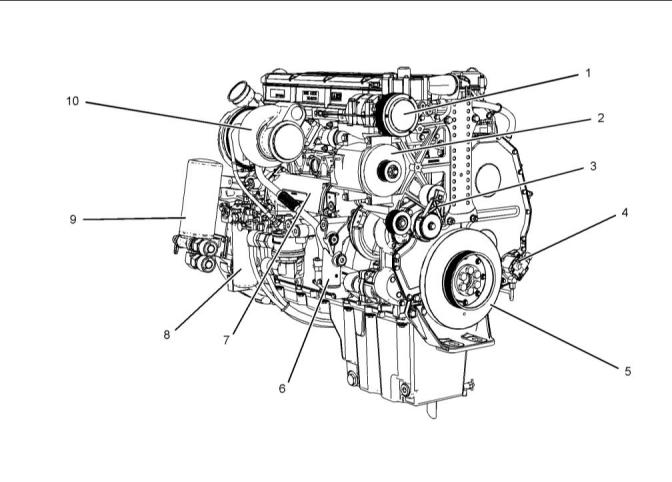
Illustration 1
g03812155
Typical example
(1) Refrigerant compressor
(2) Alternator
(3) Belt tensioner
(5) Vibration damper
(6) Coolant intake
(7) Oil cooler
(9) Engine oil filter
(10) Turbocharger
(4) Fuel transfer pump
(8) Secondary fuel filter
This document has been printed from SPI2. NOT FOR RESALE
![]()
![]()
UENR0632
5
Systems Operation Section
Illustration 2
g03812156
Typical example
(11) Engine front lifting eye
(12) Coolant outlet
(16) Flywheel housing
(17) Flywheel
(21) Oil gauge (dipstick)
(22) Air compressor
(13) Water temperatureregulator housing
(14) Engine rear lifting eye
(18) Starting motor
(19) Air intake
(23) Location for oil filler
(24) Crankcase breather
(15) Electronic Control Module (ECM)
(20) Oil drain valve
The Electronic Unit Injector (EUI) provides increased
control of the timing and increased control of the fuel
air mixture. Engine rpm is controlled by adjusting the
injection duration. Engine timing is controlled by the
precise control of fuel injection timing.
Starting the Engine
The engines ECM will automatically provide the
correct amount of fuel in order to start the engine. Do
not hold the throttle down while the engine is
cranking. If the engine fails to start in 30 seconds,
release the starting switch. Allow the starting motor to
cool for 2 minutes before the starting motor is used
again.
The Electronic Control Module (ECM) monitors the
components of the engine during operation. In the
event of a component failure, an event code will be
logged in the ECM. The electronic service tool can be
connected to the engine in order to read any logged
faults. Intermittent faults are logged and stored in
memory.
Cold Mode Operation
The ECM will set the cold start strategy when the
coolant temperature is below 18 °C (64 °F).
When the cold start strategy is activated, low idle rpm
will be increased to 1000 rpm and the power of the
engine will be limited.
Cold mode operation will be deactivated when any of
the following conditions have been met:
This document has been printed from SPI2. NOT FOR RESALE

![]()
![]()
6
UENR0632
Systems Operation Section
• Coolant temperature reaches 18 °C (64 °F).
• The engine has been running for 14 minutes.
Cold mode operation varies the fuel injection amount
and the timing for white smoke cleanup. The engine
operating temperature is usually reached before the
walk-around inspection is completed. The engine will
idle at the programmed low idle rpm in order to be put
in gear.
After the cold mode is completed, the engine should
be operated at low rpm until normal operating
temperature is reached. The engine will reach normal
operating temperature faster when the engine is
operated at low rpm and low-power demand.
i06196504
Electronic Control System
Components
The illustrations within the following sections are
typical location of the sensors or electrical
components for an industrial engine. Specific engines
may appear different due to differences in
applications.
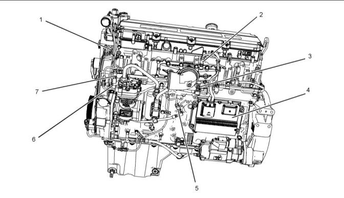
Illustration 3
g03863738
Typical example
(1) Coolant temperature sensor
(2) Inlet manifold pressure sensor
(3) Inlet air temperature sensor
(4) Electronic Control Module (ECM)
(5) Oil pressure sensor
(6) Camshaft speed timing sensor
(7) Atmospheric pressure sensor
This document has been printed from SPI2. NOT FOR RESALE
![]()
![]()
UENR0632
7
Systems Operation Section
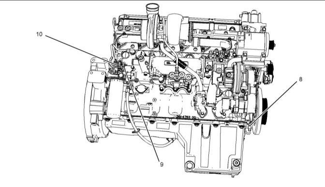
Illustration 4
g03863739
Typical example
(8) Crankshaft speed timing sensor
(9) Fuel temperature sensor
(10) Fuel pressure sensor
The electronic control system is integrally designed
into the fuel system and the air inlet and exhaust
system of the engine in order to electronically control
the fuel delivery and the injection timing. The
electronic control system provides increased timing
control and fuel air ratio control in comparison to
conventional mechanical engines. Injection timing is
achieved by precise control of injector firing time, and
engine rpm is controlled by adjusting the firing
duration. The Electronic Control Module (ECM)
energizes the solenoid in the unit injector in order to
start the injection of fuel. Also, the ECM de-energizes
the unit injector solenoids in order to stop injection of
fuel. Refer to Systems Operation, Testing and
Adjusting, “Fuel System” for a complete explanation
of the fuel injection process.
• Voltage
• Frequency
• Pulse width
The variation of the signal is in response to a change
in some specific system of the equipment. The ECM
sees the input sensor signal as information about the
condition, environment, or operation of the
equipment.
An electronic control module (ECM) receives the
input signals. Electronic circuits inside the control
component evaluate the signals from the input
components. These electronic circuits also supply
electrical energy to the output components of the
system. The electrical energy that is supplied to the
output components is based on predetermined
combinations of input signal values.
The engine uses the following types of electronic
components:
• Inputs
An output component is one that is operated by a
control module. The output component receives
electrical energy from the control component. The
output component uses that electrical energy in one
of two ways. The output component can use that
electrical energy in order to perform work. The output
component can use that electrical energy in order to
provide information.
• Controls
• Outputs
An input component is one that sends an electrical
signal to the ECM. The signal that is sent varies in
one of the following ways:
This document has been printed from SPI2. NOT FOR RESALE
![]()
![]()
8
UENR0632
Systems Operation Section
i06196634
Only use fuel that is free from contamination, that
conforms to the specifications in the Operation and
Maintenance Manual, “Fluid Recommendations” Fuel
Specifications.
Cleanliness of Fuel System
Components
Cleanliness of the Engine
NOTICE
It is important to maintain extreme cleanliness when
working on the fuel system, since even tiny particles
can cause engine or fuel system problems.
The entire engine should be washed with a high-
pressure water system. Washing the engine will
remove dirt and loose debris before a repair on the
fuel system is started. Ensure that no high-pressure
water is directed at the seals for the injectors or any
electrical connector.
Environment
When possible, the service area should be positively
pressurized. Ensure that the components are not
exposed to contamination from airborne dirt and
debris. When a component is removed from the
system, the exposed fuel connections must be closed
off immediately with suitable sealing plugs. The
sealing plugs should only be removed when the
component is reconnected. The sealing plugs must
not be reused. Dispose of the sealing plugs
immediately after use. Contact your nearest Perkins
distributor in order to obtain the correct sealing plugs.
New Components
High-pressure lines are not reusable. New high-
pressure lines are manufactured for installation in one
position only. When a high-pressure line is replaced,
do not bend or distort the new line. Internal damage
to the pipe may cause metallic particles to be
introduced to the fuel.
All new fuel filters, high-pressure lines, tube
assemblies, and components are supplied with
sealing plugs. These sealing plugs should only be
removed in order to install the new part. If the new
component is not supplied with sealing plugs then the
component should not be used.
The technician must wear suitable rubber gloves. The
rubber gloves should be disposed of immediately
after completion of the repair in order to prevent
contamination of the system.
Refueling
In order to refuel the diesel fuel tank, the refueling
pump and the fuel tank cap assembly must be clean
and free from dirt and debris. Refueling should take
place only when the ambient conditions are free from
dust, wind, and rain.
This document has been printed from SPI2. NOT FOR RESALE
![]()
![]()
![]()
UENR0632
9
Systems Operation Section
i06196641
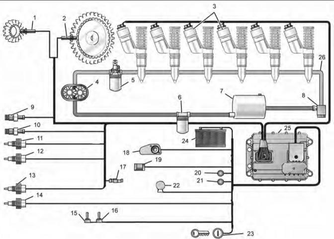
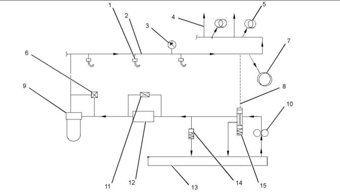
Fuel System
Illustration 5
g01721176
Typical example
(1) Primary speed/timing sensor
(2) Secondary speed/timing sensor
(3) Injectors
(10) Engine oil pressure sensor
(11) Engine coolant temperature sensor
(12) Inlet air temperature sensor
(13) Fuel temperaturesensor
(14) Engine coolant level sensor
(15) Power Take Off (PTO) ON/OFF switch
(16) PTO SET/RESUME switch
(17) Timing calibration connector
(18) Throttle position sensor
(19) SAE J1939 Data Link
(20) Warning lamp
(21) Diagnostic lamp
(22) Programmableoutputs
(23) Keyswitch
(24) Battery
(25) Electronic Control Module (ECM)
(26) Fuel manifold (rail)
(4) Fuel pump
(5) Secondary fuel filter
(6) Primary fuel filter and water separator
(7) Fuel tank
(8) Fuel pressure regulator
(9) Atmospheric pressure sensor
This document has been printed from SPI2. NOT FOR RESALE
![]()
![]()
10
UENR0632
Systems Operation Section
The Electronic Unit Injector system consists of the
following systems: the mechanical system and the
electronic system. The mechanical system is made
up of the low-pressure fuel supply system and the
electronic unit injectors. The electronic system
provides complete electronic control of all engine
functions. The electronic control system consists of
the following three types of components: input,
control and output.
There are five major components of the Electronic
Unit Injector fuel system:
• Electronic unit injectors
• Fuel transfer pump
• ECM
• Sensors
• Solenoids
The Electronic Unit Injectors produce fuel injection
pressures up to 207000 kPa (30000 psi). The
Electronic Unit Injectors also fire up to 19 times per
second at rated speed. The fuel transfer pump
supplies the injectors by drawing fuel from the tank
and by pressurizing the system between 60 and 125
PSI. The ECM is a powerful computer which controls
all major engine functions. Sensors are electronic
devices which monitor engine performance
parameters. Engine performance parameters
measure pressure, temperature, and speed. This
information is sent to the ECM via a signal. Solenoids
are electronic devices which use electronic currents
from the ECM to change engine performance. An
example of a solenoid is the Injector solenoid.
Low Pressure Fuel System
This document has been printed from SPI2. NOT FOR RESALE
![]()
![]()
UENR0632
11
Systems Operation Section
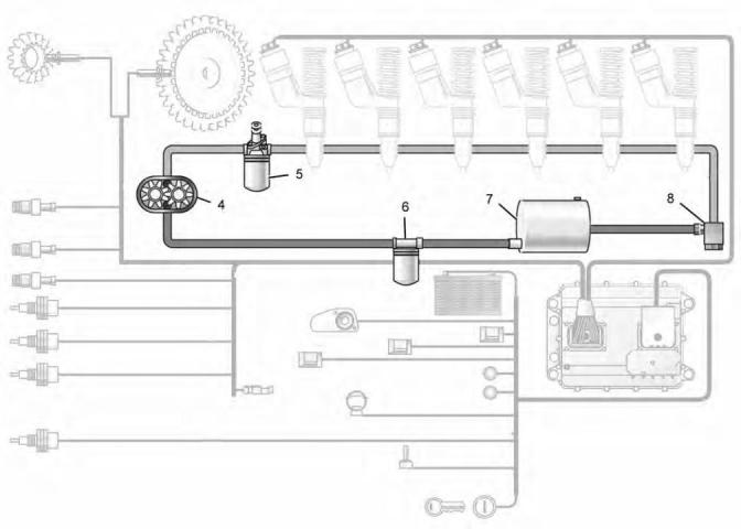
Illustration 6
g01721234
(4) Fuel pump
(5) Secondary fuel filter
(6) Primary fuel filter and water separator
(7) Fuel tank
(8) Fuel pressure regulator
This document has been printed from SPI2. NOT FOR RESALE
![]()
![]()
12
UENR0632
Systems Operation Section
The low-pressure fuel system supplies fuel from the
fuel tank to the injectors. The low-pressure fuel
system has four basic functions:
information to the ECM by a signal voltage. Actuators
are electronic devices which use electrical currents
from the ECM to change engine performance. An
example of an actuator is an injector solenoid.
• Supply fuel for combustion
Temperature Regulator for the fuel (If
Equipped)
• Supply fuel in order to cool the injectors.
• Remove air from the fuel.
Later models will not have a temperature regulator for
the fuel.
• Warm the fuel in the fuel tank.
The major parts in a low-pressure fuel system consist
of the following components:
The fuel regulator valve is located in one of the return
fuel lines. The fuel line runs from the fuel filter base to
the fuel transfer pump. The fuel regulator valve is
controlled by the temperature of the fuel. The valve is
in the open position at temperatures below 21 °C
(70 °F). The valve closes at temperatures above
27 °C (80 °F).
• Fuel tank
• Fuel transfer lines
• Primary fuel filter or water separator
• Fuel transfer pump
The temperature regulator for the fuel is used to
supply the injectors with warm fuel during cold
operation. Fuel is delivered to the injectors by a fuel
passage in the cylinder head. The injectors are
supplied with an excess of fuel. The excess fuel
removes heat from the injectors. This heated fuel will
mix with the cold fuel in the fuel tank. The fuel
regulator valve in the return fuel line mixes fuel from
the fuel tank with the excess fuel that is returning to
the fuel tank. The warm fuel increases injector life.
• Secondary fuel filter
• Fuel priming pump
• Fuel pressure regulator valve
• Fuel regulator valve
The electronic unit injectors, the fuel transfer pump,
the ECM, sensors, and solenoids are part of the low-
pressure fuel system.
Electronic Controls
The electronic control system provides complete
electronic control of all engine functions. The
In the low-pressure fuel system, the fuel is pulled from
the fuel tank to the primary fuel filter or to the water
separator. The primary fuel filter removes large debris
from the fuel before the fuel flows into the transfer
pump. The fuel transfer pump is a gear pump that
contains a pressure relief valve. Fuel flows from the
outlet port of the transfer pump to the secondary fuel
filter. The 2 micron filter removes small abrasive
contaminants from the fuel system, which can cause
damage to the unit injectors.
electronic control system consists of the following
three types of components: input, control and output.
Sensors monitor engine operating conditions. This
information is sent to the ECM. The ECM has three
main functions. The ECM provides power for the
engine electronics and monitors input signals from
the engine sensors. The ECM also acts as a governor
to control engine rpm. The ECM stores active faults,
logged faults, and logged events. The Personality
Module is the software in the ECM which contains the
specific maps that define power, torque, and RPM of
the engine. The ECM sends electrical current to the
output components in order to control engine
operation. The ECM has the following connectors:
two 70 pin harness connectors, one engine harness
connector and one vehicle harness connector. The
vehicle harness connects the ECM to the engine
control portion of the vehicle harness. The engine
control portion includes the following components.
The fuel filter base contains a hand operated fuel
priming pump. The fuel priming pump removes air
from the system when a fuel filter has been changed
or a unit injector has been changed. The priming
pump pulls fuel from the tank, around the transfer
pump and into the filter. The transfer pump pushes
fuel through the supply passage in the cylinder head
and back to the tank.
The fuel pressure regulator consists of a check valve
that is spring loaded. The pressure relief valve opens
at approximately 414 to 862 kPa (60 to 125 psi).
When the engine is in the off position and the fuel
pressure drops below 414 kPa (60 psi), the check
valve closes. The check valve closes in order to
prevent the fuel in the cylinder head from draining
back into the fuel tank. Retaining the fuel in the head
maintains a supply of fuel for the injectors during
start-up.
• Transmission
• Brake
• Clutch switches
• PTO switch
• Data links
• Check engine light
• Warning light
The ECM controls major engine functions. Sensors
are electronic devices that monitor engine
performance parameters. The pressure sensor, the
temperature sensor, and the speed sensor provide
This document has been printed from SPI2. NOT FOR RESALE
![]()
UENR0632
13
Systems Operation Section
• Engine retarder switch
• Speedometer
energized. The ECM sends a 90 V signal to the
solenoid for energizing the solenoid. By controlling
the timing of the 90 V signal, the ECM controls
injection timing. By controlling the duration of the 90 V
signal, the ECM controls the injected fuel amount.
• Tachometer
• Cooling fan solenoid
Injection timing is determined by engine rpm, and
other engine data. The ECM senses the top center
position of cylinder number 1 from the signal that is
provided by the engine speed sensor. The ECM
decides when the injection should occur relative to
the top center position. The ECM provides the signal
to the unit injector at the desired time.
The following features are part of the electronic
control system:
• Cold start strategy
• Oil pressure
Unit Injector Mechanism
• Coolant temperature warning indicator
• Automatic altitude compensation
• Variable injection timing
• Electronic engine speed governing
These features result in the following items: precise
engine speed control, very little smoke, faster cold
starting and built-in engine protection.
The ECM consists of the following two main
components: the ECM and the personality module.
The ECM is a computer and the personality module is
the software for the computer. The personality
module contains the operating maps. The operating
maps define the following characteristics of the
engine:
• Horsepower
• Torque curves
• Rpm
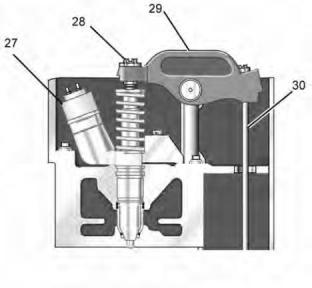
Illustration 7
g01451028
Typical examples of electronic unit injector fuel
systems.
• Other characteristics
(27) Unit injector
The ECM, the personality module, the sensors, and
the unit injectors work together in order to control the
engine. The ECM, the personality module, the
sensors, and the unit injectors cannot control the
engine alone.
(28) Adjusting nut
(29) Rocker arm assembly
(30) Pushrod
The unit injector pressurizes the fuel. The correct
amount of fuel is then injected into the cylinder block
at precise times. The ECM determines the injection
timing and the amount of fuel that is delivered. The
unit injector is operated by a camshaft lobe and a
rocker arm. The camshaft has three camshaft lobes
for each cylinder. Two lobes operate the inlet and
exhaust valves, and the other lobe operates the unit
injector mechanism. Force is transferred from the unit
injector lobe on the camshaft through the lifter to the
pushrod (30). The force of the pushrod is transferred
through rocker arm assembly (29) and to the top of
the unit injector. The adjusting nut (28) allows setting
of the unit injector adjustment. Refer to Systems
Operation/Testing and Adjusting, “Electronic Unit
Injector - Adjust” for the proper setting of the unit
injector adjustment.
The ECM determines a desired rpm that is based on
the following criteria:
• Throttle signal
• Certain diagnostic codes
• Vehicle speed signal
The ECM maintains the desired engine rpm by
sensing the actual engine rpm. The ECM calculates
the fuel amount that needs to be injected in order to
achieve the desired rpm.
Fuel Injection Timing and Delivery
Unit Injector
The ECM controls the injected fuel amount by varying
the signals to the unit injectors. The unit injectors will
inject fuel ONLY if the unit injector solenoid is
This document has been printed from SPI2. NOT FOR RESALE
![]()
![]()
![]()
![]()
14
UENR0632
Systems Operation Section
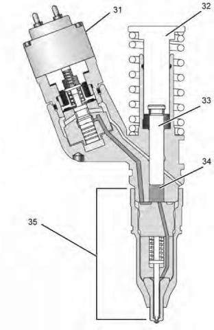
Illustration 8
g01451031
(31) Solenoid
(32) Tappet
(33) Plunger
(34) Barrel
(35) Nozzle assembly
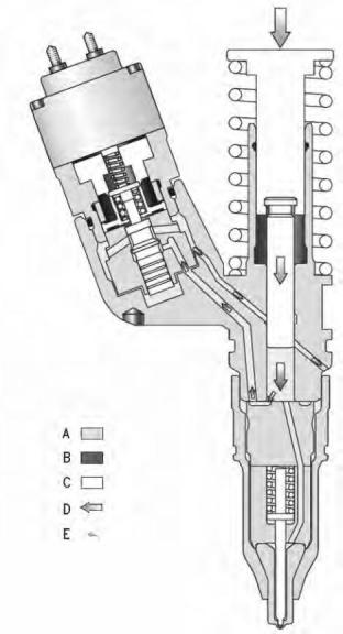
Operation of the Electronic Unit Injector
Illustration 9
g00942799
Pre-injection
The operation of the Electronic Control Unit (EUI)
consists of the following four stages: Pre-injection,
Injection, End of injection and Fill. Unit injectors use a
plunger and barrel to pump high-pressure fuel into the
combustion chamber. Components of the injector
include the tappet, the plunger, the barrel, and nozzle
assembly. Components of the nozzle assembly
include the spring, the nozzle check, and a nozzle tip.
The cartridge valve is made up of the following
components: solenoid, armature, poppet valve and
poppet spring.
(A) Fuel supply pressure
(B) Injection pressure
(C) Moving parts
(D) Mechanical movement
(E) Fuel movement.
Pre-injection metering starts with the injector plunger
and the injector tappet at the top of the fuel injection
stroke. When the plunger cavity is full of fuel, the
poppet valve is in the open position and the nozzle
check is in the open position. Fuel leaves the plunger
cavity when the rocker arm pushes down on the
tappet and the plunger. Fuel flow that is blocked by
the closed nozzle check valve flows past the open
poppet valve to the fuel supply passage in the
The injector is mounted in an injector bore in the
cylinder head which has an integral fuel supply
passage. The injector sleeve separates the injector
from the engine coolant in the water jacket. Some
engines use a stainless steel sleeve. The stainless
steel sleeve fits into the cylinder head with a light
press fit.
cylinder head. If the solenoid is energized, the poppet
valve remains open and the fuel from the plunger
cavity continues flowing into the fuel supply passage.
This document has been printed from SPI2. NOT FOR RESALE
![]()
![]()
![]()
![]()
![]()
UENR0632
15
Systems Operation Section
Illustration 10
g00942798
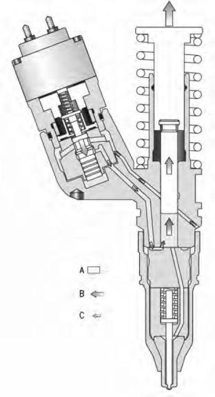
Illustration 11
g00942801
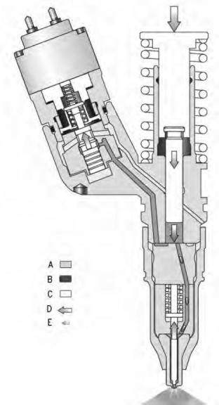
Injection
End of injection
(A) Fuel supply pressure.
(B) Injection pressure
(C) Moving parts
(A) Fuel supply pressure
(C) Moving parts
(D) Mechanical movement
(E) Fuel movement.
Injection is continuous while the injector plunger
moves in a downward motion and the energized
solenoid holds the poppet valve closed. When
injection pressure is no longer required, the ECM
stops current flow to the solenoid. When the current
flow to the solenoid stops, the poppet valve opens.
The poppet valve is opened by the fuel injector spring
and the fuel pressure. High-pressure fuel can now
flow around the open poppet valve and into the fuel
supply passage. This results in a rapid drop in
injection pressure. When the injection pressure drops
to approximately 24 MPa (3500 psi), the nozzle
check closes and injection stops. This is the end of
injection.
To start injection, the ECM sends a current to the
solenoid on the cartridge valve. The solenoid creates
a magnetic field which attracts the armature. When
the solenoid is energized, the armature assembly will
lift the poppet valve so the poppet valve contacts the
poppet seat. This is the closed position. Once the
poppet valve closes, the flow path for the fuel that is
leaving the plunger cavity is blocked. The plunger
continues to push fuel from the plunger cavity and the
fuel pressure builds up. When the fuel pressure
reaches approximately 34.5 MPa (5000 psi), the
force of the high-pressure fuel overcomes the spring
force. This holds the nozzle check in the closed
position. The nozzle check moves off the nozzle seat
and the fuel flows out of the injector tip. This is the
start of injection.
This document has been printed from SPI2. NOT FOR RESALE
![]()
![]()
![]()
![]()
![]()
16
UENR0632
Systems Operation Section
i06196481
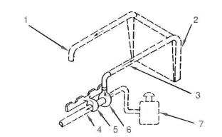
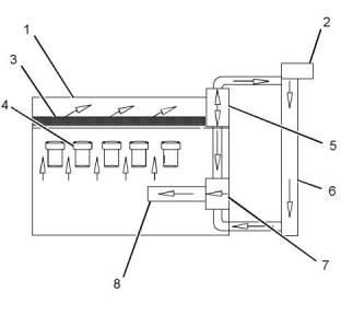
Air Inlet and Exhaust System
Illustration 13
g01046036
Air inlet and exhaust system schematic
(1) Inlet to the engine
(2) Aftercooler core
(3) Inlet air line
(4) Exhaust outlet from turbocharger
(5) Turbine side of turbocharger
(6) Compressor side of turbocharger
(7) Air cleaner
The engine components of the air inlet and exhaust
system control the quality of air and the amount of air
that is available for combustion. The components of
the air inlet and exhaust system are the following
components:
• Air cleaner
• Turbocharger
• Aftercooler
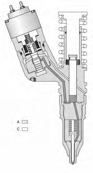
Illustration 12
g00942802
• Cylinder head
Fill
• Valves and valve system components
• Piston and cylinder
• Exhaust manifold
(A) Moving parts
(B) Mechanical movement
(C) Fuel movement.
When the plunger reaches the bottom of the barrel,
fuel is no longer forced from the plunger cavity. The
plunger is pulled up by the tappet and the tappet
spring. The upward movement of the plunger causes
the pressure in the plunger cavity to drop below fuel
supply pressure. Fuel flows from the fuel supply
passage around the open poppet and into the plunger
cavity as the plunger travels upward. When the
plunger reaches the top of the stroke, the plunger
cavity is full of fuel and fuel flow into the plunger
cavity stops. This is the beginning of pre-injection.
The turbocharger compressor wheel pulls inlet air
through the air cleaner and into the air inlet. The air is
compressed and this causes the air to become hot.
The air flows through aftercooler core (2) and the
temperature of the compressed air lowers. This helps
to provide increased horsepower output. Aftercooler
core (2) is a separate cooler core that is mounted in
front of the engine radiator. The engine fan causes
ambient air to move across both cores. This cools the
turbocharged inlet air and the engine coolant.
Air is forced from the aftercooler into inlet manifold
(1). The air flow from the inlet port into the cylinders is
controlled by inlet valves.
This document has been printed from SPI2. NOT FOR RESALE
![]()
![]()
![]()
![]()
UENR0632
17
Systems Operation Section
Turbocharger
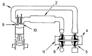
Illustration 14
g00615497
Air inlet and exhaust system
(2) Aftercooler core
(4) Exhaust outlet
(5) Turbine side of turbocharger
(6) Compressor side of turbocharger
(8) Exhaust manifold
(9) Exhaust valve
(10) Inlet valve
(11) Air inlet
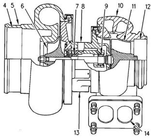
Illustration 15
g00291085
Turbocharger
Each cylinder has two inlet valves (10) and two
exhaust valves (9) in the cylinder head. The inlet
valves open on the inlet stroke. When the inlet valves
open, compressed air from the inlet port within the
inlet manifold is pushed into the cylinder. The inlet
valves close when the piston begins the compression
stroke. The air in the cylinder is compressed and the
fuel is injected into the cylinder when the piston is
near the top of the compression stroke. Combustion
begins when the fuel mixes with the air. The force of
combustion pushes the piston on the power stroke.
The exhaust valves open and the exhaust gases are
pushed through the exhaust port into exhaust
manifold (8). After the piston finishes the exhaust
stroke, the exhaust valves close and the cycle begins
again.
(4) Air inlet
(5) Compressor housing
(6) Compressor wheel
(7) Bearing
(8) Oil inlet port
(9) Bearing
(10) Turbine housing
(11) Turbine wheel
(12) Exhaust outlet
(13) Oil outlet port
(14) Exhaust inlet
Turbocharger (3) is mounted to exhaust manifold (2)
of the engine. All of the exhaust gases go from the
exhaust manifold through the turbocharger.
The exhaust gases enter the turbocharger and the
turbine wheel is turned. Because the turbocharger
turbine wheel is connected by a shaft to the
turbocharger compressor wheel, the turbine wheel
and the compressor wheel turn at very high speeds.
The rotation of the compressor wheel pulls clean air
through the compressor housing air inlet. The action
of the compressor wheel blades causes a
compression of the inlet air. This compression allows
a larger amount of air to enter the engine. With more
air in the engine, the engine is able to burn more fuel.
The overall effect is an increase in power.
Exhaust gases from the exhaust manifold flow into
the turbine side of turbocharger (5). The high
temperature exhaust gases cause the turbocharger
turbine wheel to turn. The turbine wheel is connected
to the shaft that drives the compressor wheel.
Exhaust gases from the turbocharger pass through
exhaust outlet (4), through a muffler, and through an
exhaust stack.
Bearing (7) and bearing (9) in the turbocharger use
engine oil that is under pressure for lubrication. The
lubrication for the bearings flows through oil inlet port
(8) and into the inlet port in the center section of the
turbocharger cartridge. The oil exits the turbocharger
through oil outlet port (13). The oil then returns to the
engine oil pan through the oil drain line for the
turbocharger.
This document has been printed from SPI2. NOT FOR RESALE
![]()
![]()
![]()
![]()
![]()
18
UENR0632
Systems Operation Section
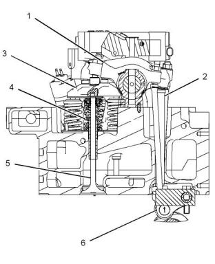
Valve System Components
Illustration 16
g01086490
(1) Rocker arm
(2) Pushrod
(3) Valve bridge
(4) Valve spring
(5) Valve
(6) Lifter
The valve system components control the flow of inlet
air into the cylinders and out of the cylinders during
engine operation. The valve mechanism also
operates the fuel injector.
The camshaft must be timed to the crankshaft in
order to get the correct relation between the piston
movement and the valve movement.
The camshaft has two camshaft lobes for each
cylinder. The lobes operate the inlet and exhaust
valves. As the camshaft turns, lobes on the camshaft
cause lifters (6) to move pushrods (2) up and down.
Upward movement of the pushrods against rocker
arms (1) results in downward movement (opening) of
valves (5).
Each cylinder has two inlet valves and two exhaust
valves. The valves are actuated at the same time by
a valve bridge (3). Valve springs (4) close the valves
when the lifters move down.
This document has been printed from SPI2. NOT FOR RESALE
![]()
![]()
![]()
UENR0632
19
Systems Operation Section
i06196479
Lubrication System
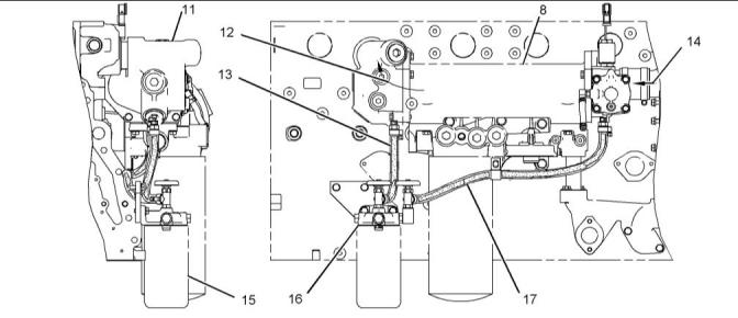
Illustration 17
g01417920
Lubrication system schematic
(1) Piston cooling jets
(6) Oil filter bypass valve
(7) Main bearings
(8) Signal line
(9) Primary engine oil filter
(10) Engine oil pump
(11) Oil cooler bypass valve
(12) Engine oil cooler
(13) Oil pan
(14) High-pressurerelief valve
(15) Oil pump bypass valve
(2) Main oil gallery in cylinder block
(3) Engine pressure sensor
(4) Oil flow to valve mechanism
(5) Camshaft journals
This document has been printed from SPI2. NOT FOR RESALE
![]()
![]()
20
UENR0632
Systems Operation Section
i02918835
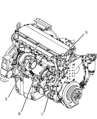
Cooling System
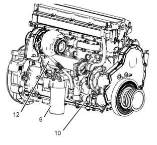
Coolant Flow
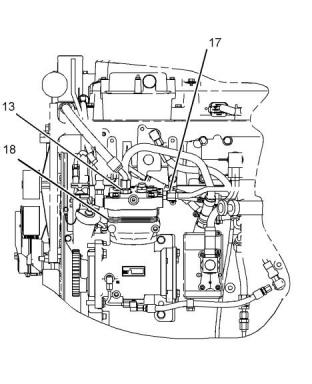
Illustration 18
g01417942
Right side view of engine
(9) Primary engine oil filter
(10) Engine oil pump
(12) Engine oil cooler
The lubrication system supplies 110 °C (230 °F)
filtered oil at approximately 275 kPa (40 psi) at rated
engine operating conditions. Oil pump bypass valve
(15) is controlled by the engine oil manifold pressure,
rather than the oil pump pressure. The engine oil
manifold pressure is independent of the pressure
drop that is caused by the engine oil filter and the
engine oil cooler.
Illustration 19
g01085911
Cooling system schematic
(1) Cylinder head
(2) Expansion tank
(3) Return manifold
(4) Cylinder liners
(5) Temperatureregulator housing
(6) Radiator
Oil cooler bypass valve (11) maintains the engine oil
temperature to 110 °C (230 °F). High-pressure relief
valve (14), which is located in the filter base, protects
the filters and other components during cold starts.
The opening pressure of the high-pressure relief
valve is 695 kPa (100 psi). The opening pressure of
the oil filter bypass valve is 170 kPa (25 psi). Engine
oil pressure sensor (3) is part of the engine protection
system.
(7) Water pump
(8) Engine oil cooler
The water pump is gear-driven. The water pump is
located on the right hand side of the engine. The
water pump supplies the coolant for the engine
cooling system. The coolant is supplied to the
following components:
• Cylinder head (1)
The turbocharger cartridge bearings are lubricated by
the oil supply line from the main oil gallery, and the oil
drain line returns the oil flow to the sump.
• Cylinder liners (4)
• Engine oil cooler (8)
• Air compressor (not shown)
• Coolant conditioner element (not shown)
This document has been printed from SPI2. NOT FOR RESALE
![]()
![]()
![]()
![]()
![]()
UENR0632
21
Systems Operation Section
The coolant is pumped through engine oil cooler (9).
The coolant then flows to the supply manifold. The
supply manifold, which is located in the cylinder
block, distributes coolant around the upper portion of
the cylinder liners. At each cylinder, the coolant flows
from the cylinder liner to the cylinder head. The
cylinder head is divided into single cylinder cooling
sections. In the cylinder head, the coolant flows
across the center of the cylinder and across the
injector seat boss. At the center of the cylinder, the
coolant flows around the injector sleeve over the
exhaust port. The coolant then exits into return
manifold (3). The return manifold collects the coolant
from each cylinder and the return manifold directs the
flow to temperature regulator housing (5). When the
coolant temperature regulator is in the closed
position, the coolant flows through the coolant
temperature regulator. This allows the coolant to flow
directly back to the water pump for recirculation by
bypassing the radiator. When the coolant temperature
regulator is in the open position, the coolant is
directed through the radiator and back to the water
pump inlet.
Supply Manifold
Cooling is provided for only the portion of the cylinder
liner above the seal in the cylinder block. The coolant
enters the cylinder block at each cylinder through slits
in the supply manifold. The supply manifold is an
integral casting in the cylinder block. The coolant
flows around the circumference of the cylinder liner
and into the cylinder head through a single drilled
passage for each liner. The coolant flow is split at
each cylinder liner so that 60 percent flows around
the cylinder liner and the remainder flows directly to
the cylinder head.
Illustration 20
g01098799
Right side view of engine
(3) Return manifold
(5) Temperature regulator housing
(7) Water pump
(8) Engine oil cooler
Water pump (8) pulls the coolant from the bottom of
radiator. The water pump is located on the right hand
side of the front timing gear housing.
Temperature Reg, ulator Housing
The water pump impeller rotates at 1.37 times the
engine speed. The water pump is driven by an idler
gear. The idler gear is turned by the crankshaft gear.
The water pump shaft is supported by two ball
bearings. One ball bearing is located in the water
pump housing. The other ball bearing is located in the
front timing gear housing. The water pump impeller
face is open. The impeller is made out of cast iron.
The rear cover is an aluminum die casting. The water
pump seal is a cartridge seal that is located on the
inlet side of the water pump in order to provide good
water flow around the seal for cooling.
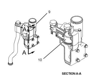
Illustration 21
g01451074
Section view of the temperature regulator housing
(9) Temperatureregulator housing
(10) Coolant temperature sensor
This document has been printed from SPI2. NOT FOR RESALE
![]()
![]()
![]()
![]()
![]()
22
UENR0632
Systems Operation Section
The coolant temperature regulator is a full flow
bypass type that is used to control the outlet
temperature of the coolant. When the engine is cold,
the coolant temperature regulator is in the closed
position. This allows the coolant to flow through the
coolant temperature regulator from the return
manifold. This allows the coolant to bypass the
radiator. The coolant goes directly to the water pump
for recirculation. As the coolant temperature
increases, the coolant temperature regulator begins
to open directing some of the coolant to the radiator
and bypassing the remainder to the water pump inlet.
At the full operating temperature of the engine, the
coolant temperature regulator moves to the open
position. This allows all the coolant flow to be directed
to the radiator. The coolant then goes to the water
pump. This route provides the maximum heat release
from the coolant. A vent line is recommended from
the manifold to the radiator overflow tank in order to
provide venting for the cooling system.
This document has been printed from SPI2. NOT FOR RESALE
![]()
UENR0632
23
Systems Operation Section
Coolant Conditioner (If Equipped)
Illustration 22
g01451075
(8) Engine oil cooler
(13) Outlet hose
(16) Coolant conditioner base
(11) Engine oil cooler elbow
(12) Coolant flow to the cylinder head
(14) Coolant flow from the water pump
(15) Coolant conditioner element
(17) Inlet hose
Some conditions of operation can cause pitting on
critical engine components. This pitting is caused by
corrosion or by cavitation erosion. The addition of a
corrosion inhibitor can keep this type of damage to a
minimum.
The precharge coolant conditioner element has more
than the normal amount of corrosion inhibitor. The
precharge coolant conditioner element is used when
a system is first filled with new coolant. This element
must add enough corrosion inhibitor in order to bring
the complete cooling system up to the correct
concentration.
Coolant conditioner element (15) is a spin-on element
that is similar to the fuel filter and to the engine oil
filter elements. The coolant conditioner element
attaches to coolant conditioner base (16) that is
mounted on the engine. Coolant flows from the water
pump through inlet hose (17) and into the coolant
conditioner base. The coolant that is conditioned then
flows through outlet hose (13) into engine oil cooler
elbow (11). There is a constant flow through the
coolant conditioner element.
The maintenance elements have a normal amount of
inhibitor and the maintenance elements are installed
at each change interval. The maintenance elements
provide enough inhibitor in order to keep the
corrosion protection at an acceptable level. In order to
provide the cooling system with protection,
maintenance elements are installed at specific
intervals.
The element has a specific amount of inhibitor for
acceptable cooling system protection. As the coolant
flows through the element, the corrosion inhibitor,
which is a dry material, disperses into the coolant.
The coolant and the inhibitor are mixed to the correct
concentration. Two basic types of elements are used
for the cooling system, the precharge and the
maintenance elements. Each type of element has a
specific use. Each type of element must be used
correctly to get the necessary concentration for
cooling system protection. The elements also contain
a filter. Even after the conditioner material is
dispersed, the elements should be left in the system
so the coolant flows through the filter.
This document has been printed from SPI2. NOT FOR RESALE
![]()
![]()
24
UENR0632
Systems Operation Section
Coolant for Air Compressor
• Camshaft bearings
• Valve mechanism
The manifold on the right supplies oil to the manifold
on the left. The oil travels through the cut above the
number one main bearing and the cut above the
number four main bearing.
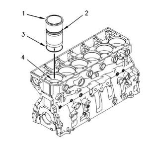
Illustration 24
g00762739
Illustration 23
g01451179
Cylinder liners (1) are seated on a ridge (4) in the
middle of the cylinder wall between the crankcase
and the coolant jacket. The ridge is created by a
counterbore in the cylinder block. The cylinder liners
have a lip (2) which rests on the ridge. The seals of
the coolant jacket are located in the upper regions
and middle regions of the cylinder liners. The lower
barrier uses a D-ring seal (3) that is located above the
seating surface of the cylinder liner. The upper barrier
is the head gasket which is above the coolant jacket.
(13) Outlet hose
(17) Inlet hose
(18) Air compressor
The coolant that is used for air compressor (3) comes
from the cylinder head through inlet hose (2). The
coolant exits the air compressor through outlet hose
(1) and flows back to the cylinder head.
i02773143
The cylinder block has seven main bearings in order
to support the crankshaft. Each main bearing cap is
fastened to the cylinder block with two bolts.
Basic Engine
Pistons, Rings, and Connecting
Rods
Cylinder Block
The cylinder block is a unique design with a deep
counterbore that supports the cylinder liner. The
cylinder block also forms the coolant jacket. Two oil
manifolds are provided in the cylinder block for
engine lubrication. The manifold on the lower right
side of the cylinder block provides oil to the following
components:
The high compression ratio of the engine requires the
use of steel one piece pistons.
The pistons have three rings:
• Compression ring
• Intermediate ring
• Oil ring
• Piston cooling jets
• Crankshaft bearings
• Oil filter base
The manifold on the upper left side of the cylinder
block provides oil to the following components:
This document has been printed from SPI2. NOT FOR RESALE
![]()
![]()
![]()
![]()
![]()
UENR0632
25
Systems Operation Section
The rings are located in grooves in the piston. The
rings seal the crankcase from the combustion gases
and the rings also provide control of the engine oil.
The design of the compression ring is a barrel face
with a plasma face coating. The design of the
intermediate ring is a tapered shape and a chrome
finish. The oil ring is double railed with a coil spring
expander. The oil ring has a ground profile and a
chrome finish.
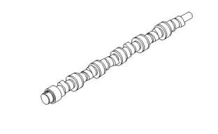
Camshaft
The connecting rod is a conventional design. The cap
is fastened to the shank by two bolts that are
threaded into the shank. Each side of the small end of
the connecting rod is machined at an angle of 12
degrees in order to fit within the piston cavity. This
allows a larger surface area on the piston, and
connecting rod in order to minimize bearing load.
Crankshaft
Illustration 25
g00762808
The crankshaft converts the linear motion of the
pistons into rotational motion. The crankshaft drives a
group of gears (front gear train) on the front of the
engine. The front gear train provides power for the
following components:
The camshaft has three lobes at each cylinder in
order to operate the unit injector, the exhaust valves,
and the inlet valves. Seven bearings support the
camshaft. The camshaft is driven by an idler gear that
is turned by the crankshaft in the front gear train.
Each bearing journal is lubricated from the oil
manifold in the cylinder block. A thrust pin that is
located at the rear of the block positions the camshaft
through a circumferential groove. The groove is
machined at the rear of the camshaft. Timing of the
camshaft is accomplished by aligning marks on the
crankshaft gear, idler gear, and camshaft gear with
each other.
• Camshaft
• Water pump
• Engine oil pump
• Air compressor
• Fuel transfer pump
• Accessory drive
The injector lobe on the camshaft has a modified
profile. The modified profile produces multiple
injections.
The crankshaft is held in place by seven main
bearings. The oil holes and the oil grooves in the shell
of the upper bearing supply oil to the connecting rod
bearings. The oil holes for the connecting rod
bearings are located at the following main bearing
journals: 2, 3, 5 and 6.
Vibration Damper
The force from combustion in the cylinders and from
driveline components will cause the crankshaft to
twist. This is called torsional vibration. If the vibration
is too great, the crankshaft will be damaged. Driveline
components can excite torsional stress. This stress
will cause damage to components. The vibration
damper limits the torsional vibrations to an acceptable
amount in order to prevent damage to the crankshaft.
Hydrodynamic seals are used at both ends of the
crankshaft to control oil leakage. The hydrodynamic
grooves in the seal lip move lubrication oil back into
the crankcase as the crankshaft turns. The front seal
is located in the front housing. The rear seal is
installed in the flywheel housing.
The viscous vibration damper is installed on the front
of the crankshaft. The viscous vibration damper has a
weight in a case. The space between the weight and
the case is filled with a viscous fluid. The weight
moves in the case in order to limit the torsional
vibration.
i06137706
Electrical System
Engine Electrical System
The electrical system has the following separate
circuits:
This document has been printed from SPI2. NOT FOR RESALE
![]()
![]()
![]()
26
UENR0632
Systems Operation Section
• Charging
The voltage regulator is a solid-state electronic
switch. The voltage regulator senses the voltage in
the system. The voltage regulator switches ON and
OFF many times per second in order to control the
field current for the alternator. The alternator uses the
field current in order to generate the required voltage
output.
• Starting (If equipped)
• Accessories with low amperage
The charging circuit is in operation when the engine is
running. An alternator makes electricity for the
charging circuit. A voltage regulator in the circuit
controls the electrical output in order to keep the
battery at full charge.
NOTICE
Never operate the alternator without the battery in the
circuit. Making or breaking an alternator connection
with heavy load on the circuit can cause damage to
the regulator.
The starting circuit is activated only when the start
switch is activated.
Charging System Components
Alternator
The alternator is driven by a belt from the crankshaft
pulley. This alternator is a three-phase, self-rectifying
charging unit, and the regulator is part of the
alternator.
The alternator design has no need for slip rings and
the only part that has movement is the rotor
assembly. All conductors that carry current are
stationary. The following conductors are in the circuit:
• Field winding
• Stator windings
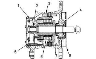
Illustration 26
g00425518
Typical alternator components
• Six rectifying diodes
• Regulator circuit components
(1) Regulator
(2) Roller bearing
(3) Stator winding
(4) Ball bearing
(5) Rectifier bridge
(6) Field winding
(7) Rotor assembly
(8) Fan
The rotor assembly has many magnetic poles that
look like fingers with air space between each of the
opposite poles. The poles have residual magnetism.
The residual magnetism produces a small magnetic
field between the poles. As the rotor assembly begins
to turn between the field winding and the stator
windings, a small amount of alternating current (AC)
is produced. The AC current is produced in the stator
windings from the small magnetic field. The AC
current is changed to direct current (DC) when the AC
current passes through the diodes of the rectifier
bridge. The current is used for the following
applications:
Starting System Components
Starting Solenoid
• Charging the battery
• Supplying the accessory circuit that has the low
amperage
• Strengthening the magnetic field
The first two applications use the majority of the
current. As the DC current increases through the field
windings, the strength of the magnetic field is
increased. As the magnetic field becomes stronger,
more AC current is produced in the stator windings.
The increased speed of the rotor assembly also
increases the current and voltage output of the
alternator.
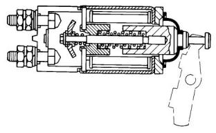
Illustration 27
g00317613
Typical starting solenoid
This document has been printed from SPI2. NOT FOR RESALE
![]()
![]()
![]()
![]()
![]()
![]()
![]()
UENR0632
27
Systems Operation Section
When two sets of solenoid windings are used, the
windings are called the hold-in winding and the pull-in
winding. Both sets of windings have the same
number of turns around the cylinder, but the pull-in
winding uses a wire with a larger diameter. The wire
with a larger diameter produces a greater magnetic
field (1). When the start switch is closed, part of the
current flows from the battery through the hold-in
windings. The rest of the current flows through the
pull-in windings to the motor terminal. The current
then flows through the motor to ground. Solenoid (2)
is fully activated when the connection across the
battery and the motor terminal is complete. When
solenoid (2) is fully activated, the current is shut off
through the pull-in windings. At this point, only the
smaller hold-in windings are in operation. The hold-in
windings operate for the duration of time that is
required in order to start the engine. Solenoid (2) will
now draw less current from the battery, and the heat
that is generated by solenoid (2) will be kept at an
acceptable level.
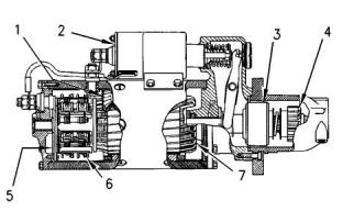
Illustration 28
g00425521
Typical starting motor components
(1) Field
(2) Solenoid
(3) Clutch
(4) Pinion
(5) Commutator
(6) Brush assembly
(7) Armature
The starting solenoid (2) is an electromagnetic switch
that performs the following basic operations:
• The starting solenoid (2) closes the high current
starting motor circuit with a low current start switch
circuit.
• The starting solenoid (2) engages the pinion of the
starting motor (4) with the ring gear.
Solenoid (2) has windings (one or two sets) around a
hollow cylinder. A plunger that is spring loaded is
inside the cylinder. The plunger can move forward
and backward. When the start switch is closed and
electricity is sent through the windings, a magnetic
field (1) is made. The magnetic field (1) pulls the
plunger forward in the cylinder. This moves the shift
lever in order to engage the pinion drive gear with the
ring gear. The front end of the plunger then makes
contact across the battery and motor terminals of
solenoid (2). Next, the starting motor begins to turn
the flywheel of the engine.
When the start switch is opened, current no longer
flows through the windings. The spring now pushes
the plunger back to the original position. At the same
time, the spring moves the pinion gear away from the
flywheel.
This document has been printed from SPI2. NOT FOR RESALE
![]()
![]()
![]()
28
UENR0632
Fuel System
Testing And Adjusting
Section
2. Install a suitable fuel flow tube with a visual sight
gauge in the fuel return line. When possible, install
the sight gauge in a straight section of the fuel line
that is at least 304.8 mm (12 inches) long. Do not
install the sight gauge near the following devices
that create turbulence:
Fuel System
• Elbows
• Relief valves
• Check valves
i02773147
Fuel System - Inspect
Observe the fuel flow during engine cranking. Look
for air bubbles in the fuel. If there is no fuel in the
sight gauge, prime the fuel system. Refer to
System Operation, Testing and Adjusting, “Fuel
System - Prime” for more information. If the engine
starts, check for air in the fuel at varying engine
speeds. When possible, operate the engine under
the conditions which have been suspect of air in
the fuel.
A problem with the components that send fuel to the
engine can cause low fuel pressure. This can
decrease engine performance.
1. Check the fuel level in the fuel tank. Ensure that
the vent in the fuel cap is not filled with dirt.
2. Check all fuel lines for fuel leakage. The fuel lines
must be free from restrictions and faulty bends.
Verify that the fuel return line is not collapsed.
3. Install a new fuel filter.
4. Cut the old filter open with a suitable filter cutter.
Inspect the filter for excess contamination.
Determine the source of the contamination. Make
the necessary repairs.
5. Service the primary fuel filter (if equipped).
6. Operate the hand priming pump (if equipped). If
excessive resistance is felt, inspect the fuel
pressure regulating valve. If uneven resistance is
felt, test for air in the fuel. Refer to Systems
Operation, Testing and Adjusting, “Air in Fuel -
Test” for more information.
7. Remove any air that may be in the fuel system.
Refer to Systems Operation, Testing and
Adjusting, “Fuel System - Prime”.
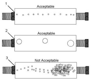
Illustration 29
g01096678
(1) A steady stream of small bubbles with a diameter of
approximately 1.60 mm (0.063 inch) is an acceptable amount
of air in the fuel.
(2) Bubbles with a diameter of approximately 6.35 mm (0.250 inch)
are also acceptable if there is two seconds to three seconds
intervals between bubbles.
i02773148
Air in Fuel - Test
(3) Excessive air bubbles in the fuel are not acceptable.
3. If excessive air is seen in the sight gauge in the fuel
return line, install a second sight gauge at the inlet
to the fuel transfer pump. If a second sight gauge
is not available, move the sight gauge from the fuel
return line and install the sight gauge at the inlet to
the fuel transfer pump. Observe the fuel flow
during engine cranking. Look for air bubbles in the
fuel. If the engine starts, check for air in the fuel at
varying engine speeds.
This procedure checks for air in the fuel. This
procedure also assists in finding the source of the air.
1. Examine the fuel system for leaks. Ensure that the
fuel line fittings are properly tightened. Check the
fuel level in the fuel tank. Air can enter the fuel
system on the suction side between the fuel
transfer pump and the fuel tank.
This document has been printed from SPI2. NOT FOR RESALE
![]()
![]()
![]()
UENR0632
29
Fuel System
If excessive air is not seen at the inlet to the fuel
transfer pump, the air is entering the system after
the fuel transfer pump. Proceed to Step 6.
i06196492
Electronic Unit Injector - Adjust
If excessive air is seen at the inlet to the fuel
transfer pump, air is entering through the suction
side of the fuel system.
To avoid personal injury, always wear eye and
face protection when using pressurized air.
4. Pressurize the fuel tank to the recommendations of
the OEM in order to avoid damage to the fuel tank.
Check for leaks in the fuel lines between the fuel
tank and the fuel transfer pump. Repair any leaks
that are found. Check the fuel pressure in order to
ensure that the fuel transfer pump is operating
properly. For information about checking the fuel
pressure, see System Operation, Testing and
Adjusting, “Fuel System Pressure - Test”.
5. If the source of the air is not found, disconnect the
supply line from the fuel tank and connect an
external fuel supply to the inlet of the fuel transfer
pump. If this corrects the problem, repair the fuel
tank or the stand pipe in the fuel tank.
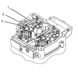
Illustration 30
g01126970
Injector Mechanism
(1) Rocker arm
(2) Adjustment screw
(3) Locknut
6. If the injector sleeve is worn or damaged,
combustion gases may be leaking into the fuel
system. Also, if the O-rings on the injector sleeves
are worn, missing, or damaged, combustion gases
may leak into the fuel system.
Follow the procedure in order to adjust the electronic
unit injectors:
1. Put the No. 1 piston at the top center position on
the compression stroke. Refer to Systems
Operation, Testing and Adjusting, “Finding Top
Center Position for No. 1 Piston”.
a.
Cylinders 3, 5, and 6 can be adjusted with
cylinder 1 at Top Center compression stroke.
b.
c.
Loosen the locknut.
Turn the adjustment screw until the screw
contacts the electronic unit injector.
d.
e.
f.
Tighten the adjustment screw to an additional
two turns.
Turn the adjustment screw counterclockwise
for 2.5 turns.
Turn the adjustment screw until the screw
contacts the electronic unit injector.
g.
h.
Turn the adjustment screw through 180
degrees in a clockwise direction.
Tighten the locknut to a torque of 55 N·m
(41 lb ft).
This document has been printed from SPI2. NOT FOR RESALE
![]()
![]()
![]()
![]()
![]()
免费热线
400-100-8969 15088860848
400-100-8969 15088860848
机组销售
0574-26871589 15267810868
0574-26871589 15267810868
配件销售
0574-26886646 15706865167
0574-26886646 15706865167
维修热线
0574-26871569 18658287286
0574-26871569 18658287286
手机端

微信公众号