 English
 Espaol
 Franais
 阿拉伯
阿拉伯 中文(简)
中文(简) Deutsch
 Italiano
 Português
 日本
日本 韩国
韩国 български
 hrvatski
 esky
esky Dansk
Dansk Nederlands
 suomi
suomi Ελληνικ
 印度
印度 norsk
norsk Polski
 Roman
Roman русский
 Svenska
 Perkins2206D-E13TA故障排除维修技术资料,Perkins2206D-E13TA故障排除维修技术资料技术支持中心,Perkins2206D-E13TA故障排除维修技术资料代理商,Perkins2206D-E13TA故障排除维修技术资料销售服务中心,Perkins2206D-E13TA故障排除维修技术资料价格规格资料查询,宁波日昕动力科技有限公司

Perkins2206D-E13TA故障排除维修技术资料
详细描述
Troubleshooting
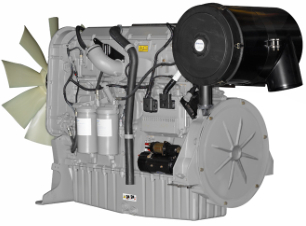
2206D-E13TA Industrial Engine
Table of Contents
Valve Lash Is Excessive .................................... 117
Valve Rotator or Spring Lock Is Free................... 118
Troubleshooting Section
Circuit Tests
Air Shutoff - Test................................................ 120
CAN Data Link - Test ......................................... 127
Coolant Level - Test........................................... 132
Data Link - Test................................................. 138
Electrical Power Supply - Test ............................ 143
Ether Starting Aid - Test..................................... 150
Indicator Lamp - Test......................................... 157
Injector Solenoid - Test ...................................... 160
Power Take-Off - Test........................................ 168
Retarder - Test.................................................. 174
Sensor Calibration Required - Test ..................... 180
Sensor Signal (Analog, Active) - Test.................. 183
Sensor Signal (Analog, Passive) - Test ............... 191
Sensor Supply - Test (8 V Supply) ...................... 198
Sensor Supply - Test (5V Supply) ....................... 204
Speed Control - Test.......................................... 206
Speed/Timing - Test .......................................... 208
Introduction
General Information ..............................................4
Welding Precaution ...............................................4
Electronic Service Tools.........................................5
Electronic System Overview
System Overview..................................................9
Component Location ........................................... 11
Diagnostic Capabilities ........................................13
Programmable Parameters..................................14
Electrical Connectors ..........................................16
Wiring Information...............................................20
Configuration Parameters
Configuration Parameters....................................21
Diagnostic Trouble Codes
Diagnostic Trouble Codes....................................28
Service
Customer Passwords ........................................ 214
Factory Passwords............................................ 214
ECM Will Not Accept Factory Passwords ............ 214
Electronic Service Tool Does Not Communicate ..215
Test ECM Mode ................................................ 221
Injector Trim File - Install.................................... 222
ECM Software - Install....................................... 223
ECM - Replace ................................................. 224
Electrical Connectors - Inspect........................... 225
Timing - Calibrate.............................................. 228
Event Codes
Event Codes ......................................................36
Symptom Troubleshooting
Symptom Troubleshooting ...................................42
Acceleration Is Poor or Throttle Response Is Poor .42
Alternator Problem ..............................................44
Battery Problem..................................................46
Coolant Contains Fuel.........................................46
Coolant Contains Oil ...........................................47
Coolant Level Is Low ...........................................50
Coolant Temperature Is High................................51
Cylinder Is Noisy.................................................54
ECM Does Not Communicate with Other Modules.56
Engine Cranks but Does Not Start ........................57
Engine Does Not Crank .......................................59
Engine Has Early Wear........................................61
Engine Has Mechanical Noise (Knock) .................63
Engine Misfires, Runs Rough or Is Unstable..........66
Engine Overspeeds.............................................68
Engine Shutdown Occurs Intermittently ................70
Engine Stalls at Low RPM....................................72
Engine Top Speed Is Not Obtained.......................74
Engine Vibration Is Excessive ..............................77
Exhaust Has Excessive Black Smoke...................78
Exhaust Has Excessive White Smoke...................80
Exhaust System Contains Oil...............................83
Exhaust Temperature Is High ...............................84
Fuel Consumption Is Excessive............................87
Fuel Pressure Is High ..........................................89
Fuel Pressure Is Low...........................................94
Fuel Temperature Is High.....................................98
Intake Manifold Air Temperature Is High.............. 104
Oil Consumption Is Excessive............................ 105
Oil Contains Coolant ......................................... 107
Oil Contains Fuel .............................................. 110
Oil Pressure Is Low ........................................... 111
Power Is Intermittently Low or Power Cutout Is
Index Section
Index................................................................ 233
Intermittent...................................................... 114
This document has been printed from SPI2. NOT FOR RESALE
![]()
4
UENR4542
Introduction
Troubleshooting Section
Introduction
Fault Detection and Reporting
The ECM monitors inputs from the sensors and
inputs from the applications control system. Software
in the ECM interprets the inputs. The software
determines if the inputs are operating correctly. A
diagnostic trouble code is activated when the
software detects a problem with an input.
The ECM broadcasts the codes on two data links.
The data links are the Perkins Data Link (PDL) and
J1939 CAN data link. The electronic service tool
must communicate on both data links in order to
service the engine. If a problem is suspected with
one of the data links, refer to Troubleshooting, “Data
Link - Test” or Troubleshooting, “CAN Data Link -
Test”.
i05957486
General Information
Overview
The codes can be displayed on the electronic service
tool and optional operator interfaces.
These engines are equipped with an electronic
control system. The system consists of a computer,
sensors, and software. The system provides these
capabilities:
Troubleshooting
As a reference, simplified schematics for each of the
engines subsystems are included with each of the
circuit tests that are in this manual. For an accurate
representation of the entire electrical schematic that
is for your application, refer to the Electrical System
Schematic.
• Control of the engine
• Applications control system interface
• Fault detection and reporting
During troubleshooting, inspect all harness
Electronic Control System
connections before any component is replaced. If
these connections are not clean and tight, continuous
electrical problems or intermittent electrical problems
can result. Check that the wires are pushed into the
connectors completely. Make sure that the
The Electronic Control Module (ECM) is a computer
that controls the operation of the engine.
The ECM contains a flash file. The flash file is the
software for the ECM. The flash file contains the
operating maps. The operating maps define the
following characteristics of the engine:
connections are tight before other tests are made.
Failure of an electrical component may cause the
failure of other components. Always attempt to
correct the cause of an electrical failure before you
replace a component. If wire insulation is punctured,
repair the damage.
• Horsepower
• Torque curves
• Engine speed (rpm)
Refer to Troubleshooting, “System Overview” for
additional information on the electronic control
system.
i05957501
Welding Precaution
Application Interface
The ECM interfaces with the machine via software
and an electrical connector on the ECM. The
software can be configured.
Proper welding procedures are necessary in
order to avoid damage to the engine Electronic
Control Module (ECM), to the Clean Emissions
Module (CEM), if equipped, to sensors, and to
associated components. Also consider
components that are for the driven equipment.
Remove the component that requires welding.
When welding on an engine that is equipped with
an ECM and removal of the component is not
possible, the following procedure must be
followed. This procedure provides the minimum
amount of risk to the electronic components.
The applications control system provides inputs to
the electrical connector on the ECM in order to
indicate the status of switches. Configure the ECM in
order to interpret the inputs.
The ECM provides outputs for the applications
control system via the electrical connector in order to
control lamps, solenoids, and other devices.
Configure the ECM to match the configuration of the
applications control system.
1. Stop the engine. Remove the electrical power from
the ECM.
This document has been printed from SPI2. NOT FOR RESALE
![]()
![]()
UENR4542
5
Introduction
2. Ensure that the fuel supply to the engine is turned
7. Use standard welding procedures to weld the
off.
materials together.
3. Disconnect the negative battery cable from the
battery. If a battery disconnect switch is installed,
open the switch.
i05957511
Electronic Service Tools
4. Disconnect all electronic components from the
wiring harnesses. Electronic components include
the following components:
Service Tools
• Electronic components for the driven
equipment
Most of the tools that are listed in Table 1 are
required to enable a service technician to perform the
test procedures in this manual. Some of the devices
may be specific to the type of Electronic Control
Module (ECM) that is being used.
• The engine ECM
• Sensors
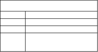
Table 1
Service Tools
NOTICE
Do NOT use electrical components (ECM or sensors)
or electronic component grounding points for ground-
ing the welder.
Part
Number
Description
N/A
4 mm Allen Wrench
Wedge Removal Tool
28170079
T400920
CH11155
Wire Removal Tool (14-GA TO 18-GA, RED)
Crimp Tool (12−AWG TO 18−AWG)
GE50038
GE50039
Transducer
Transducer Adapter
GE50040
CVT0019
Cable As
Adapter Cable As (3-PIN BREAKOUT)
T400922
T400923
Adapter Cable As (40-PIN BREAKOUT)
Harness (40-PIN)
(For ADEM 2 ECM (two 40-pin connectors))
GE50037 / Adapter Cable As (70-PIN BREAKOUT)
2900A025
T400924
N/A
(For ADEM 3 ECM (two 70-pin connectors) and
for ADEM 4 ECM (one 70-pin connector and one
120-pin connector))
Adapter Cable As (120-PIN BREAKOUT)
(For ADEM 4 ECM (one 70-pin connector and one
120-pin connector))
Torque Wrench (capable of applying 1.5 N·m
(13.3 lb in))
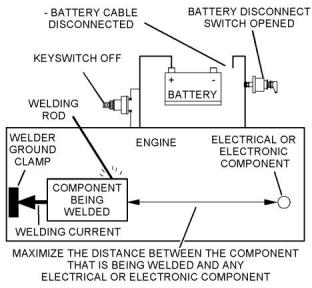
Illustration 1
g01143634
Service welding guide (typical diagram)
Repair Kits for Connectors
5. When possible, connect the welder ground clamp
directly to the engine component that will be
welded. Place the clamp as close as possible to
the weld. A close connection will reduce the
possibility of welding current damage to the engine
bearings, to the electrical components, and to
other components.
U5MK1110
U5MK8194
Connector Repair Kit (AMPSEAL)
Connector Repair Kit (Deutsch connector )
Bypass Harnesses for the ECM
T400925
Power Cable
(Stand alone cable for ADEM 2 ECM)
6. Protect the wiring harnesses from welding debris
and/or from the welding spatter.
(continued)
This document has been printed from SPI2. NOT FOR RESALE

![]()
![]()
![]()
![]()
![]()
6
UENR4542
Introduction
(Table 1, contd)
• Programming of flash file
• Parameter programming
Service Tools
Part
Number
Description
• Copy configuration function for Electronic Control
Module (ECM) replacement
2900A038
Wiring Harness (ECM BYPASS)
(The bypass harness connects to the battery. The
bypass harness is used with the following har-
nesses for different types of electronic control
modules.)
• Data logging
• Graphs (real time)
Table 3 lists the service tools that are required in
order to use the Electronic Service Tool.
Table 3
T400926
Harness (ENGINE ECM BYPASS)
(For ADEM 3 ECM and ADEM 4 ECM)
28170107
Harness (ENGINE ECM BYPASS)
(For A4:E2 ECM (Two 64-pin connectors))
Service Tools for the Use of the Electronic Service
Tool
Description
Single Use Program License
Data Subscription for All Engines
Part Number
Two short jumper wires may be needed to check the
continuity of some wiring harness circuits by shorting
two adjacent terminals together in a connector. A
long extension wire may also be needed to check the
continuity of some wiring harness circuits.
-(1)
-
(1)
27610164
TIPSS Adapter Kit (Electronic Service Tool to
Optional Service Tools
the ECM interface)
or
Table 2 lists the optional service tools that may be
needed during testing or repair.
27610401
Perkins CA3 Kit
(1)
Refer to Perkins Engine Company Limited.
Table 2
Note: For more information on the Electronic Service
Tool and the PC requirements, refer to the
documentation that accompanies the software for the
Electronic Service Tool.
Part Number
Description
U5MK1092
Spoon Probe Kit (MULTIMETER)
-
or
-
Suitable Digital Pressure Indicator
or
Engine Pressure Group
-
-
Suitable Battery Load Tester
Suitable Temperature Adapter
(MULTIMETER)
2900A038
Harness as
Perkins Electronic Service Tool
The Electronic Service Tool can display the following
information:
• Status of all pressure sensors and temperature
sensors
• Programmable parameter settings
• Active diagnostic codes and logged diagnostic
codes
• Logged events
• Histograms
The Electronic Service Tool can also be used to
perform the following functions:
• Diagnostic tests
• Calibrations
This document has been printed from SPI2. NOT FOR RESALE

![]()
UENR4542
7
Introduction
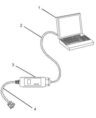
Connecting the Electronic Service Tool
and the TIPSS Adapter
4. Place the keyswitch in the ON position. If the
Electronic Service Tool and the TIPSS adapter do
not communicate with the Electronic Control
Module (ECM), refer to the diagnostic procedure
Troubleshooting, “Electronic Service Tool Does
Not Communicate”.
Connecting the Electronic Service Tool
and the CA3 Kit
Illustration 2
g03738342
(1) Personal Computer (PC)
(2) Adapter Cable (Computer Serial Port)
(3) TIPSS adapter
(4) Adapter Cable Assembly
Note: Items (2), (3) and (4) are part of the TIPSS
adapter kit.
Illustration 3
g01121866
Use the following procedure in order to connect the
Electronic Service Tool and the TIPSS Adapter.
(1) Personal Computer (PC)
(2) Adapter Cable (Computer Serial Port)
(3) CA3 adapter
1. Turn the keyswitch to the OFF position.
(4) Adapter Cable Assembly
2. Connect cable (2) between the “COMPUTER” end
of TIPSS adapter (3) and the RS232 serial port of
PC (1).
Note: Items (2), (3) and (4) are part of the CA3 kit.
Use the following procedure in order to connect the
Electronic Service Tool and the CA3 Adapter.
Note: The Adapter Cable Assembly (4) is required to
connect to the USB port on computers that are not
equipped with an RS232 serial port.
1. Turn the keyswitch to the OFF position.
2. Connect cable (2) between the “COMPUTER” end
3. Connect cable (4) between the “DATA LINK” end
of TIPSS adapter (3) and the service tool
connector.
of CA3 adapter (3) and a USB port of PC (1).
3. Connect cable (4) between the “DATA LINK” end
of CA3 adapter (3) and the service tool connector.
This document has been printed from SPI2. NOT FOR RESALE
![]()

![]()
![]()
![]()
![]()
8
UENR4542
Introduction
4. Place the keyswitch in the ON position. If the
Electronic Service Tool and the CA3 adapter do
not communicate with the Electronic Control
Module (ECM), refer to the diagnostic procedure
Troubleshooting, “Electronic Service Tool Does
Not Communicate”.
This document has been printed from SPI2. NOT FOR RESALE
![]()
UENR4542
9
Electronic System Overview
Electronic System
Overview
• Reduced warm-up time
• Reduced white smoke
Cold mode is activated whenever the engine
temperature falls below a predetermined value. Cold
mode remains active until the engine temperature
rises above a predetermined value or until a time limit
is exceeded.
i06299999
System Overview
Fuel Injection
The ECM controls the amount of fuel that is injected
by varying the signals to the injectors. The injector
will pump fuel only if the injector solenoid is
System Operation
energized. The ECM sends a high voltage signal to
the solenoid. This high voltage signal energizes the
solenoid. By controlling the timing and the duration of
the high voltage signal, the ECM can control injection
timing and the engine RPM.
This engine is electronically controlled. Each cylinder
has an electronic unit injector. The Electronic Control
Module (ECM) sends a signal to each injector
solenoid in order to control the operation of the fuel
injection system.
The flash file inside the ECM sets certain limits on the
amount of fuel that can be injected. The “FRC Fuel
Limit” is used to control the air/fuel ratio for control of
emissions. The “FRC Fuel Limit” is a limit that is
based on the turbocharger outlet pressure. A higher
turbocharger outlet pressure indicates that there is
more air in the cylinder. When the ECM senses a
higher turbocharger outlet pressure, the ECM
increases the “FRC Fuel Limit” . When the ECM
increases the “FRC Fuel Limit” , the ECM allows
more fuel into the cylinder. The “FRC Fuel Limit” is
programmed into the ECM at the factory. The “FRC
Fuel Limit” cannot be changed.
Electronic Controls
The electronic system consists of the following
components: the ECM, the Mechanically Actuated
Electronically Controlled Unit Injectors (MEUI), the
wiring harness, the switches and the sensors. The
ECM is the computer. The flash file is the software for
the computer. The flash file contains the operating
maps. The operating maps define the following
characteristics of the engine:
• Horsepower
The “Rated Fuel Limit” is a limit that is based on the
power rating of the engine and on engine rpm. The
“Rated Fuel Limit” is similar to the rack stops and to
the torque spring on a mechanically governed
engine. The “Rated Fuel Limit” provides the power
curves and the torque curves for a specific engine
family and for a specific engine rating. The “Rated
Fuel Limit” is programmed into the ECM at the
factory. The “Rated Fuel Limit” cannot be changed.
• Torque curves
The ECM determines the timing and the amount of
fuel that is delivered to the cylinders. These decisions
are based on the actual conditions and/or on the
desired conditions at any given time.
The ECM compares the desired engine speed to the
actual engine speed. The actual engine speed is
determined through a signal from the engine speed/
timing sensor. The desired engine speed is
determined with the following factors:
Once the ECM determines the amount of fuel that is
required, the ECM must determine the timing of the
fuel injection. The ECM calculates the TOP CENTER
position of each cylinder from the engine speed/
timing sensor signal. The ECM decides when fuel
injection should occur relative to the top center
position and the ECM provides the signal to the
injector at the desired time. The ECM adjusts timing
for optimum engine performance, for optimum fuel
economy, and for optimum control of white smoke.
• Throttle signal
• Other input signals from sensors
• Certain diagnostic codes
If the desired engine speed is greater than the actual
engine speed, the ECM injects more fuel in order to
increase the actual engine speed.
Programmable Parameters
Certain parameters that affect the engine operation
may be changed with the electronic service tool. The
parameters are stored in the ECM, and some
parameters are protected from unauthorized changes
by passwords. These passwords are called factory
passwords.
Cold Mode
The ECM limits engine power during cold mode
operation and the ECM modifies injection timing
during cold mode operation. Cold mode operation
provides the following benefits:
• Increased cold weather starting capability
This document has been printed from SPI2. NOT FOR RESALE
![]()
10
UENR4542
Electronic System Overview
Passwords
Several system configuration parameters and most
logged events are protected by factory passwords.
Factory passwords are available only to Perkins
distributors. Refer to Troubleshooting, “Factory
Passwords” for additional information.
This document has been printed from SPI2. NOT FOR RESALE
![]()
UENR4542
11
Electronic System Overview
i06300000
Component Location
This document has been printed from SPI2. NOT FOR RESALE
![]()
12
UENR4542
Electronic System Overview
Illustration 4
g03891675
This document has been printed from SPI2. NOT FOR RESALE

![]()
![]()
UENR4542
13
Electronic System Overview
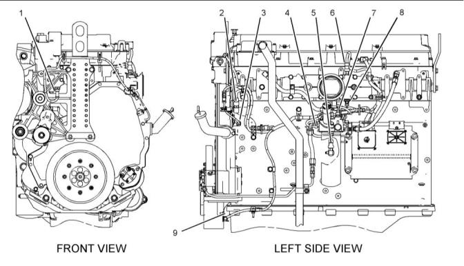
2206D Engines
Illustration 5
g01099946
Locations of the sensors on 2206D engines
(1) Engine coolant temperature sensor
(2) Atmospheric pressure sensor
(3) Secondary engine speed/timing sensor
(4) Fuel pressure sensor
(5) Engine oil pressure sensor
(6) Boost pressure sensor
(7) Fuel temperature sensor
(8) Intake manifold air temperature sensor
(9) Primary engine speed/timing sensor
i05957583
Event Code – An event code is generated by the
detection of an abnormal engine operating condition.
For example, an event code will be generated if the
oil pressure is too low. In this case, the event code
indicates the symptom of a problem. Generally, event
codes indicate abnormal operating conditions or
mechanical problems rather than electrical problems.
Diagnostic Capabilities
Diagnostic Codes
The engines Electronic Control Module (ECM) can
monitor the circuitry between the ECM and the
engines components. The ECM can also monitor the
engines operating conditions. If the ECM detects a
problem, a code is generated.
Codes can have two different states:
• Active
• Logged
There are two categories of codes:
• Diagnostic code
Active Codes
An active code indicates that a problem is present.
Service the active code first. For the appropriate
troubleshooting procedure for a particular code, refer
to the appropriate troubleshooting procedure.
• Event code
Diagnostic Code – A diagnostic code indicates an
electrical problem such as a short circuit or an open
circuit in the engines wiring or in an electrical
component.
This document has been printed from SPI2. NOT FOR RESALE
![]()
![]()
14
UENR4542
Electronic System Overview
Logged Codes
active but the code may become logged.
Logged codes may not indicate that a repair is
needed. The problem may have been temporary.
Logged codes may be useful to help troubleshoot
intermittent problems. Logged codes can also be
used to review the performance of the engine and of
the electronic system.
The codes are logged and stored in the ECM
memory. The problem may have been repaired and/
or the problem may no longer exist. If the system is
powered, an active diagnostic code may be
generated whenever a component is disconnected. If
the component is reconnected, the code is no longer
i06534836
Programmable Parameters
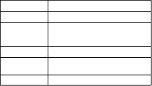
Table 4
Diagnostic Trouble Codes
Code Description
J1939 Code
(code descriptions may
vary)
PDL Code
Comments
The Electronic Control Module (ECM) detects one of the following
conditions:
· One or more of the programmable parameters have not been
programmed
Engine Protection System · One or more of the injector trim files are not programmed.
630-2
268-2
Configuration : Erratic, Inter-
mittent, or Incorrect
The diagnostic code will only be active. The check engine lamp is il-
luminated when this diagnostic code is active.
Engine performance may be affected by unprogrammed parame-
ters. The unprogrammed parameters determine the action that is
taken by the ECM. The ECM may use a default torque map or the
ECM may limit the engine to low idle.
Programming Parameters
When the “Test ECM Mode” is activated, an internal
timer sets a 24-hour clock. This clock will count down
only when the ECM is powered. If the new ECM fixes
the problem, the engine can be released whilst the
“Test ECM Mode” is still active. After the ECM has
counted down the 24-hour period, the ECM will exit
the “Test ECM Mode” . The parameters, the
accumulated hours, and the engine serial number will
be permanently programmed into the new ECM. The
new ECM can no longer be used for another engine
or for a test ECM.
The electronic service tool can be used to view
certain parameters that can affect the operation of
the engine. The electronic service tool can also be
used to change certain parameters. The parameters
are stored in the Electronic Control Module (ECM).
Some of the parameters are protected from
unauthorized changes by passwords. Parameters
that can be changed have a tattletale number. The
tattletale number shows if a parameter has been
changed.
Note: When the “Test ECM Mode” is activated, the
“Personality Module Code” is 0. After the ECM has
counted down the 24-hour period, the “Personality
Module Code” depends on the application.
Test ECM Mode
“Test ECM Mode” is a feature on the electronic
service tool that is used to troubleshoot an engine
that may have a problem with the Electronic Control
Module (ECM).
If the new ECM does not resolve the problem, and 24
hours has not expired, the ECM can be used as a
new ECM. Anytime prior to the 24-hour limit of the
“Test ECM Mode” , a new engine serial number and
new parameters can be reprogrammed.
If an application supports this feature, the electronic
service tool will allow a new ECM to be used
temporarily as a test ECM. If an application does not
support this feature, refer to Troubleshooting, “ECM -
Replace”.
1. Search for the latest flash file for the engine.
Note: If a newer software version is available for the
engine, install the newest software on the suspect
ECM. If the new software does not fix the problem,
continue with this procedure.
This document has been printed from SPI2. NOT FOR RESALE

![]()
UENR4542
15
Electronic System Overview
2. Use the “Copy Configuration/ECM Replacement”
feature on the electronic service tool to copy the
configuration parameters from the suspect ECM to
your personal computer (PC). If the “Copy
Configuration/ECM Replacement” feature cannot
be used, record the programmed values into the
“Parameters Worksheet” in system configuration
parameters Troubleshooting, “System
Configuration Parameters”. Record the injector
serial numbers from the “Calibrations” screen
under the “Service” menu on the electronic service
tool.
If the problem is resolved with the new ECM,
remove the original ECM and permanently install
the new ECM.
If the new ECM does not fix the problem, the
original ECM is not the problem. Remove the new
ECM before the 24-hour timer expires. Reconnect
the original ECM.
Flash Programming
Flash Programming – Flash programming is a
method of programming or updating the flash file in
an Electronic Control Module (ECM).
The electronic service tool is utilized to flash program
a flash file into the ECM. The flash programming
transfers the flash file from the PC to the ECM.
Note: Some applications use injectors that have trim
codes or injector trim files that are associated with
the injectors. If injector trim codes are necessary, the
injector trim codes are printed on the injector. If
injector trim files are necessary, the injector serial
numbers are necessary for obtaining the correct
injector trim files from the electronic service tool. The
injector trim file is a number that is specific to each
unit injector. The ECM uses this number to
Flash Programming a Flash File
1. Obtain the part number for the new flash file.
Note: If you do not have the part number for the flash
file, use “PTMI” on the Perkins secured web site.
compensate for manufacturing variations between
individual injectors. If any of the injectors are
replaced, the injector trim files must be programmed
for the new injectors. Also, if the ECM is replaced, all
the injector trim files must be programmed into the
new ECM.
Note: You must have the engine serial number to
search for the part number of the flash file.
2. Connect the electronic service tool to the
diagnostic connector.
3. Turn the keyswitch to the ON position. Do not start
the engine.
3. Disconnect the suspect ECM. Temporarily connect
the new ECM to the engine. Do not mount the new
ECM on the engine.
4. Select “WinFlash” from the “Utilities” menu on the
electronic service tool.
4. Program the correct flash file into the new ECM.
Note: If “WinFlash” will not communicate with the
ECM, refer to Troubleshooting, “Electronic Service
Tool Does Not Communicate”.
Note: The “Test ECM Mode” must be activated
before the engine serial number is programmed into
the new ECM. “Test ECM Mode” can only be
activated if the engine serial number has not already
been programmed during normal operation of the
ECM. A new ECM can never be used as a test ECM
after the engine serial number is programmed.
5. Flash program the flash file into the ECM.
a.
b.
Select the engine ECM under the “Detected
ECMs” .
5. Start the “Test ECM Mode” on the electronic
service tool. Access the feature through the
“Service” menu. The electronic service tool will
display the status of the “Test ECM Mode” and the
hours that are remaining for the “Test ECM Mode”
.
Press the “Browse” button to select the part
number of the flash file that will be
programmed into the ECM.
c.
d.
When the correct flash file is selected, press
the “Open” button.
Note: If the “Copy Configuration/ECM Replacement”
feature cannot be used, program the values from the
“Parameters Worksheet” .
Verify that the “File Values” match the
application. If the “File Values” do not match
the application, search for the correct flash file.
6. Use the “Copy Configuration/ECM Replacement”
feature on the electronic service tool to program
the correct parameters into the new ECM.
e.
f.
When the correct flash file is selected, press
the “Begin Flash” button.
The electronic service tool will indicate when
flash programming has been successfully
completed.
7. Program the engine serial number into the new
ECM.
This document has been printed from SPI2. NOT FOR RESALE
![]()
16
UENR4542
Electronic System Overview
6. Access the “Configuration” screen under the
“Service” menu to determine the parameters that
require programming.
“WinFlash” Error Messages
If any error messages are displayed during flash
programming, click the “Cancel” button to stop the
process. Access the information about the “ECM
Summary” under the “Information” menu. Ensure that
you are programming the correct flash file for your
engine.
7. Start the engine and check for proper operation.
Check that there are no active diagnostic codes.
i06300006
Electrical Connectors
This document has been printed from SPI2. NOT FOR RESALE
![]()
UENR4542
17
Electronic System Overview
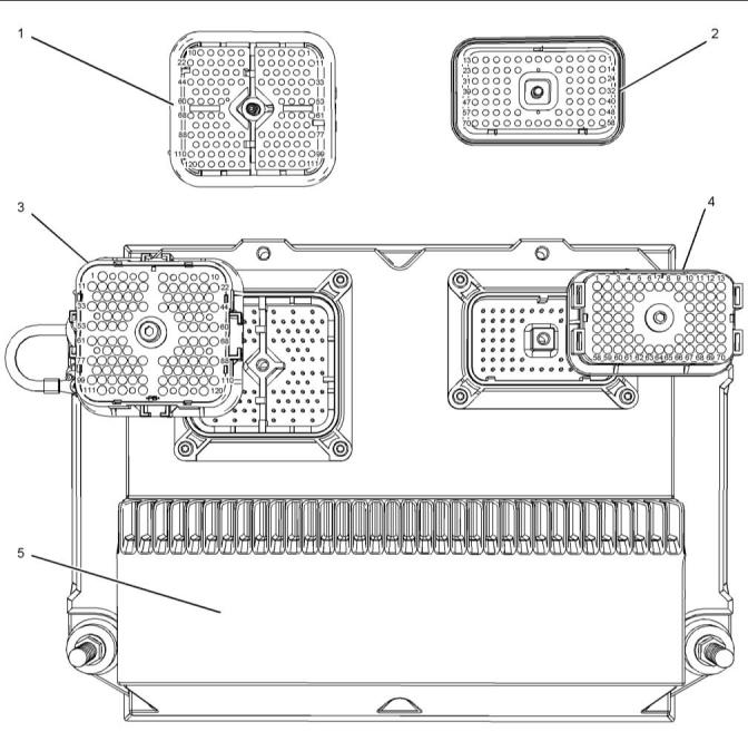
Connectors for the Electronic Control
Module (ECM)
Illustration 6
g02141017
Locations of the components at the Engine ECM
(1) P2 ECM connector (ECM side)
(2) P1 ECM connector (ECM side)
(3) P2 ECM connector (harness side)
(4) P1 ECM connector (harness side)
(5) Engine ECM
This document has been printed from SPI2. NOT FOR RESALE
![]()
![]()
18
UENR4542
Electronic System Overview
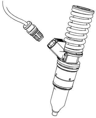
Injector Connectors
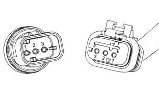
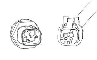
Sensor Connectors
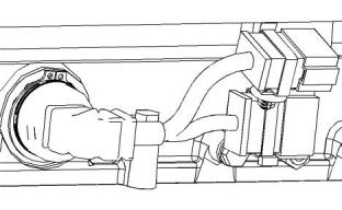
Connectors at the Valve Cover
Analog Sensor Connector (active)
Illustration 7
g01746753
Illustration 9
g01240891
Connector at the Injector
Analog Sensor Connector (passive)
Illustration 10
g01241538
Illustration 8
g01717773
Typical HD injector
This document has been printed from SPI2. NOT FOR RESALE
![]()
![]()
![]()
![]()
![]()
![]()
![]()
![]()
![]()
UENR4542
19
Electronic System Overview
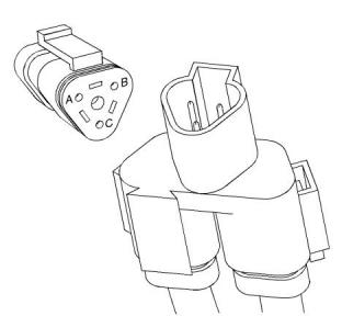
Connectors for the Termination Resistor
Ampseal Connector (typical)
Illustration 11
g01355248
Illustration 13
g02219254
Refer to Special Instruction, REHS2556 for additional
information
Engine Speed/Timing Connector
Illustration 12
g01155187
This document has been printed from SPI2. NOT FOR RESALE
![]()
![]()
![]()

![]()
![]()
![]()
![]()
20
UENR4542
Electronic System Overview
Deutsch Connectors (typical)
Table 5
Color Codes for the Harness Wire
Color Code
Color Code
Color
Color
BK
BR
RD
Black
GN
Green
Brown
Red
BU
PU
Blue
Purple
OR
YL
Orange
Yellow
GY
Gray
WH
PK
White
Pink
For example, a wire identification of A701-GY(Grey)
on the schematic would signify a gray wire with the
circuit number A701. A701-GY(Grey) identifies the
power circuit for the No. 1 Injector solenoid.
Illustration 14
g02220494
i05958935
Wiring Information
The connection of any electrical equipment and
the disconnection of any electrical equipment
may cause an explosion hazard which may result
in injury or death. Do not connect any electrical
equipment or disconnect any electrical equip-
ment in an explosive atmosphere.
The wiring schematics are revised periodically. The
wiring schematics will change as updates are made
to the engine harness. For the most current
information, always check the revision number of the
schematic. Use the schematic with the latest revision
number.
Harness Wire Identification
Wires are identified with 11 solid colors. The circuit
number is stamped on the wire at a 25 mm (1 inch)
spacing. Table 5 lists the wire colors and the color
codes.
This document has been printed from SPI2. NOT FOR RESALE

![]()
![]()
![]()
![]()
![]()
UENR4542
21
Configuration Parameters
Configuration Parameters
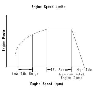
“Top Engine Limit” (TEL)
i06300016
Configuration Parameters
System configuration parameters are parameters
that affect the emissions and the power of the engine.
Default values for the parameters are programmed at
the factory. Some parameters may be changed by
the customer in order to suit the needs of the specific
application.
Parameter Descriptions
“Equipment ID”
“Equipment ID” allows the customer to enter a
description into the Electronic Control Module (ECM)
in order to identify the machine. A maximum of 17
characters may be entered in the field. This
parameter is only for reference by the customer. This
parameter is not required.
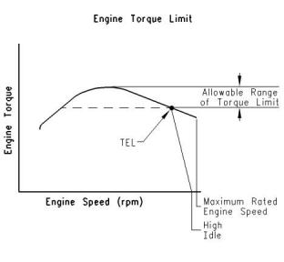
Illustration 15
g00763900
“TEL” is a customer programmable parameter that
defines the maximum allowable engine speed for
maximum power. “TEL” can be programmed up to
the maximum rated engine speed. “TEL” is defined
along the engine's lug curve.
“Engine Serial Number”
Program the “Engine Serial Number” to match the
engine serial number that is stamped on the engine
information plate. If the ECM is replaced, the engine
serial number from the engine information plate must
be programmed into the new ECM.
Programming the “Top Engine Limit”
In certain instances, the “TEL” must be programmed
using the procedure outlined below.
Note: When you are requesting factory passwords,
always use the engine serial number that is
programmed in the ECM.
“Rating Number”
The “Rating Number” corresponds to the selected set
of performance maps for the application. This
selected set of performance maps comes out of
several unique sets of maps that are resident in the
flash file. The dealer and/or the OEM will need to
select the appropriate rating tier, if more than one
rating tier is present. The rating tiers are “A” through
“E” .
Note: Factory passwords are required in order to
change the “Rating Number” .
This document has been printed from SPI2. NOT FOR RESALE
![]()
![]()
![]()
22
UENR4542
Configuration Parameters
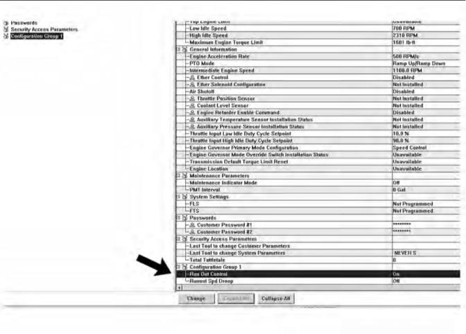
Illustration 16
g03891712
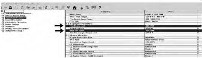
1. Program “Run Out Control” to “ON” , then
disconnect from the electronic service tool and
completely remove battery power from the ECM.
This document has been printed from SPI2. NOT FOR RESALE
![]()
![]()
UENR4542
23
Configuration Parameters
Illustration 17
g02897641
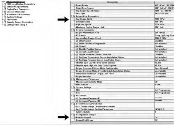
2. Restore the power. After power is restored,
program “Run Out Control” to “ON” . “Top Engine
,Limit” is now “2100 RPM” instead of “Unavailable”
.
Illustration 18
g03891716
3. Program “Top Engine Limit” to “1800 RPM” .
Program “High Idle Speed” to “1800 RPM” .
This document has been printed from SPI2. NOT FOR RESALE
![]()
![]()
![]()
“Engine Accel. Rate”
“Intermediate Engine Speed”
24
UENR4542
Configuration Parameters
“Engine Accel. Rate” determines the rate of change
“Intermediate Engine Speed” defines the speed for
the engine when the intermediate engine speed
switch is activated. This parameter can be
programmed to any engine speed between “Low Idle
Speed” and “TEL” . Engine speed will increase or
engine speed will decrease at the rate that is defined
by the programmed value for “Engine Accel. Rate” .
of the engine speed (acceleration or deceleration)
during PTO operation. This rate of change is also
used to achieve intermediate engine speed.
“Low Idle Speed”
“Low Idle Speed” is the minimum allowable operating
speed for the engine. This parameter can be
programmed between 600 and 1400 rpm.
“Maximum Engine Torque Limit”
“PTO Mode”
“PTO Mode” allows the ECM to be programmed to
either one of the two PTO configurations that are
available.
“Ramp Up/Ramp Down” – When “PTO Mode” is
programmed to “Ramp Up/Ramp Down” , the ECM
allows PTO operation with traditional features.
“Set/Resume” – When “PTO Mode” is programmed
to “Set/Resume” , the ECM allows PTO operation
with enhanced features.
“High Idle Speed”
Illustration 20
g00817759
“Engine Torque Limit” can be used to limit torque
output to the programmed value when the torque limit
switch is activated.
“FLS” (Full Load Setting)
“FLS” is a number that represents the adjustment to
the fuel system that was made at the factory in order
to fine-tune the fuel system. The correct value for this
parameter is stamped on the engine information
plate. Factory passwords are required in order to
change this parameter.
“FTS” (Full Torque Setting)
“FTS” is similar to “FLS” . Factory passwords are
required in order to change this parameter.
Illustration 19
g00763900
“High Idle Speed” is the maximum no-load engine
speed when the throttle or the PTO switch is in the
maximum position.
“Ether Control”
Program the “Ether Control” to “Enabled” if an ether
injection system is installed on the engine. This
action allows the ECM to control ether injection. If the
engine is not equipped with ether, program this
parameter to “Disabled” .
Note: “High Idle Speed” cannot be programmed
lower than “TEL” .
This document has been printed from SPI2. NOT FOR RESALE
![]()

![]()
![]()
![]()
![]()
“Air Shutoff”
“Aux Temp Sensor Installation Status”
UENR4542
25
Configuration Parameters
“Air Shutoff” allows the ECM to be programmed for
Program “Aux Temp Enable” to “Installed” if an
auxiliary temperature sensor is installed. This action
will allow the Perkins Messenger Driver Information
Display to monitor the temperature of another
system. Program this parameter to “Not Installed” if
an auxiliary temperature sensor is not installed.
operation of an air shutoff system. If this parameter is
programmed to “Installed” , the ECM will activate the
air shutoff solenoid in the event of an engine
overspeed condition.
Note: If an engine overspeed condition occurs and
“Air Shutoff” is programmed to “Enabled” , the
switched power to the ECM must be cycled and the
air shutoff solenoid must be manually reset before
the engine will restart.
“Maintenance Indicator Mode”
The ECM records data that is related to equipment
maintenance. The ECM will activate the maintenance
indicator lamp when scheduled maintenance is due.
The maintenance indicator lamp can be reset by
actuating the maintenance clear switch. The
maintenance interval may be based on operating
hours or on fuel consumption. The ECM provides
information that pertains to maintenance intervals
and the last maintenance that was performed.
“PM1 Interval”
“PM1 Interval” allows the customer to define the
maintenance interval if “Maintenance Indicator Mode”
is programmed to one of the manual options. Refer to
the engine's Operation and Maintenance Manual for
more information.
“Throttle Position Sensor”
Program the “Throttle Position Sensor” to “Installed” if
a throttle position sensor is used for desired speed
control. Otherwise program this parameter to “Not
Installed” .
“Coolant Level Sensor”
Program the “Coolant Level Sensor” to “Installed” if a
coolant level sensor is installed on the engine.
Otherwise program this parameter to “Not Installed” .
“Aux Press Sensor Installation Status”
Program “Aux Press Enable” to “Installed” if an
auxiliary pressure sensor is installed. This action will
allow the Perkins Messenger Driver Information
Display to monitor the pressure of another system.
Program this parameter to “Not Installed” if an
auxiliary pressure sensor is not installed.
This document has been printed from SPI2. NOT FOR RESALE
![]()
26
UENR4542
Configuration Parameters
System Configuration Parameters
Table 6
System Configuration Parameters
Required
Password
Parameter
Available Range or Options
Default
ECM Identification Parameters
“Equipment ID”
17 alphanumeric characters
0XX00000 or XXX00000
“NOT PROGRAMMED”
None
None
“Engine Serial Number”
0XX00000
“ECM Serial Number”
“Read Only” (1)
Software Dependent
“Software Gp Part Number”
“Software Gp Release Date”
Selected Engine Rating
“Rating Number”
Read Only (1)
Read Only (1)
Software Dependent
Software Dependent
Software Dependent
Software Dependent
Software Dependent
Software Dependent
Software Dependent
Customer
“Rated Power”
Read Only (1)
“Rated Peak Torque”
“Top Engine Speed Range”
“Test Spec”
Read Only (1)
Read Only (1)
Read Only (1)
“Top Engine Limit”
Customer
None
“Speed Control”
“Engine Governor Primary Mode”
“Speed Control”
“Min/Max”
50 to 1000
600 to 1400
“Engine Accel. Rate”
“Low Idle Speed”
50
None
None
700
“Ramp Up/Ramp Down”
“Set/Resume”
“PTO Mode”
“Ramp Up/Ramp Down”
None
“High Idle Speed”
1800 to 2310
2310
1100
Customer
None
“Intermediate Engine Speed”
“Maximum Engine Torque Limit”
Programmed “Low Idle” to “TEL”
Software Dependent
None
“Customer Password #1”
“Customer Password #2”
“FLS” (Full Load Setting)
“FTS” (Full Torque Setting)
8 alphanumeric characters
8 alphanumeric characters
- 128 to 127
Blank
Blank
0
Customer
Customer
Factory
Factory
-128 to 127
0
“No Ether”
“Continuous Flow”
“Ether Control”
“Air Shutoff”
“No Ether”
“Disabled”
None
None
“Enabled”
“Disabled”
“OFF”
“Auto Fuel”
“Auto Hour”
“Man Fuel”
“Man Hour”
“Maintenance Indicator Mode”
“OFF”
None
(continued)
This document has been printed from SPI2. NOT FOR RESALE

![]()
UENR4542
27
Configuration Parameters
(Table 6, contd)
System Configuration Parameters
Available Range or Options
Required
Password
Parameter
Default
100 to 750 Hours
or
250 Hours
or
“PM1 Interval”
None
3785 to 28390 L (1000 to 7500 US gal)
9463 L (2500 US gal)
“Installed”
“Not Installed”
“Throttle Position Sensor”
“Coolant Level On”
“Not Installed”
“Not Installed”
None
None
“Installed”
“Not Installed”
“Last Tool to change Customer
Parameters”
Read Only (1)
“Last Tool to change System
Parameters”
Read Only (1)
“On”
“Off”
“Aux Temp Sensor Installation Status”
“Off”
“Off”
None
None
“Aux Press Sensor Installation
Status”
“On”
“Off”
“Total Tattletale”
Read Only (1)
(1)
The parameter can only be viewed. No changes are allowed.
This document has been printed from SPI2. NOT FOR RESALE

![]()
28
UENR4542
Diagnostic Trouble Codes
Diagnostic Trouble Codes
i06300002
Diagnostic Trouble Codes
Diagnostic Trouble Codes in J1939
Order
Table 7 lists the diagnostic trouble codes that apply to
the engine. The codes are listed in J1939 order. Use
the electronic service tool to determine the codes that
are active or logged. Then refer to the appropriate
troubleshooting procedure for more information.
Table 7
List of Diagnostic Trouble Codes
J1939 Code and Description
PDL Code and Description
Troubleshooting Procedure
91–3
Accelerator Pedal Position #1 : Voltage Above
Normal
91–3
Throttle Position Sensor : Voltage Above
Normal
Troubleshooting, “Speed Control - Test”
Troubleshooting, “Speed Control - Test”
Troubleshooting, “Speed Control - Test”
91–4
Accelerator Pedal Position #1 : Voltage Below
Normal
91–4
Throttle Position Sensor : Voltage Below
Normal
91–8
91–8
Accelerator Pedal Position #1 : Abnormal Fre-
quency, Pulse Width or Period
Throttle Position Sensor : Abnormal Fre-
quency, Pulse Width, or Period
94–3
Engine Fuel Delivery Pressure : Voltage Above
Normal
94–3
Fuel Delivery Pressure Sensor : Voltage
Above Normal
Troubleshooting, “Sensor Signal (Analog, Ac-
tive) - Test”
94–4
Engine Fuel Delivery Pressure : Voltage Below Fuel Delivery Pressure Sensor : Voltage Below
94–4
Troubleshooting, “Sensor Signal (Analog, Ac-
tive) - Test”
Normal
Normal
94–13
Engine Fuel Delivery Pressure : Out of
Calibration
94–13
Fuel Delivery Pressure Sensor : Out of
Calibration
Troubleshooting, “Sensor Calibration Required
- Test”
100–3
Engine Oil Pressure : Voltage Above Normal
100–3
Engine Oil Pressure Sensor : Voltage Above
Normal
Troubleshooting, “Sensor Signal (Analog, Ac-
tive) - Test”
100–4
Engine Oil Pressure : Voltage Below Normal
100–4
Engine Oil Pressure Sensor : Voltage Below
Normal
Troubleshooting, “Sensor Signal (Analog, Ac-
tive) - Test”
100–13
Engine Oil Pressure : Out of Calibration
100–13
Engine Oil Pressure Sensor : Out of
Calibration
Troubleshooting, “Sensor Calibration Required
- Test”
105–3
Engine Intake Manifold #1 Temperature : Volt- Intake Manifold Air Temperature Sensor : Volt-
age Above Normal age Above Normal
172–3
Troubleshooting, “Sensor Signal (Analog, Pas-
sive) - Test”
(continued)
This document has been printed from SPI2. NOT FOR RESALE

![]()
UENR4542
29
Diagnostic Trouble Codes
(Table 7, contd)
105–4
Engine Intake Manifold #1 Temperature : Volt- Intake Manifold Air Temperature Sensor : Volt-
172–4
Troubleshooting, “Sensor Signal (Analog, Pas-
sive) - Test”
age Below Normal
age Below Normal
108–3
Barometric Pressure : Voltage Above Normal Atmospheric Pressure Sensor : Voltage Above
Normal
274–3
Troubleshooting, “Sensor Signal (Analog, Ac-
tive) - Test”
108–4
Barometric Pressure : Voltage Below Normal Atmospheric Pressure Sensor : Voltage Below
Normal
274–4
Troubleshooting, “Sensor Signal (Analog, Ac-
tive) - Test”
110–3
Engine Coolant Temperature : Voltage Above Engine Coolant Temperature Sensor : Voltage
110–3
Troubleshooting, “Sensor Signal (Analog, Ac-
tive) - Test”
Normal
Above Normal
110–4
Engine Coolant Temperature : Voltage Below Engine Coolant Temperature Sensor : Voltage
110–4
Troubleshooting, “Sensor Signal (Analog, Ac-
tive) - Test”
Normal
Below Normal
168-2
Battery Potential / Power Input #1 : Erratic, In- Electrical System Voltage : Erratic, Intermit-
168-2
Troubleshooting, “Electrical Power Supply -
Test”
termittent, or Incorrect
tent, or Incorrect
168-3
Battery Potential / Power Input #1 : Voltage
Above Normal
168-3
Electrical System Voltage : Voltage Above
Normal
Troubleshooting, “Electrical Power Supply -
Test”
168-4
Battery Potential / Power Input #1 : Voltage
Below Normal
168-4
Electrical System Voltage : Voltage Below
Normal
Troubleshooting, “Electrical Power Supply -
Test”
174–3
Engine Fuel Temperature 1 : Voltage Above
Normal
174–3
Fuel Temperature Sensor : Voltage Above
Normal
Troubleshooting, “Sensor Signal (Analog, Pas-
sive) - Test”
174–4
Engine Fuel Temperature 1 : Voltage Below
Normal
174–4
Fuel Temperature Sensor : Voltage Below
Normal
Troubleshooting, “Sensor Signal (Analog, Pas-
sive) - Test”
190–8
190–8
Troubleshooting, “Speed/Timing - Test”
Engine Speed : Abnormal Frequency, Pulse Engine Speed Sensor : Abnormal Frequency,
Width, or Period
Pulse Width, or Period
441–3
Auxiliary Temperature #1 : Voltage Above
Normal
1836–3
Auxiliary Temperature Sensor : Voltage Above
Normal
Troubleshooting, “Sensor Signal (Analog, Pas-
sive) - Test”
441–4
Auxiliary Temperature #1 : Voltage Below
Normal
1836–4
Auxiliary Temperature Sensor : Voltage Below
Normal
Troubleshooting, “Sensor Signal (Analog, Pas-
sive) - Test”
626-5
Engine Start Enable Device 1 : Current Below Ether Injection Control Solenoid : Current Be-
Normal
2417-5
Troubleshooting, “Ether Starting Aid - Test”
Troubleshooting, “Ether Starting Aid - Test”
Troubleshooting, “Programmable Parameters”
Troubleshooting, “ECM Software - Install”
low Normal
626-6
Engine Start Enable Device 1 : Current Above
Normal
2417-6
Ether Injection Control Solenoid : Current
Above Normal
630-2
Calibration Memory : Erratic, Intermittent, or
Incorrect
268-2
Programmed Parameter Fault : Erratic, Inter-
mittent, or Incorrect
631–2
Calibration Module : Erratic, Intermittent, or
Incorrect
253–2
Personality Module : Erratic, Intermittent, or
Incorrect
(continued)
This document has been printed from SPI2. NOT FOR RESALE
免费热线
400-100-8969 15088860848
400-100-8969 15088860848
机组销售
0574-26871589 15267810868
0574-26871589 15267810868
配件销售
0574-26886646 15706865167
0574-26886646 15706865167
维修热线
0574-26871569 18658287286
0574-26871569 18658287286
手机端

微信公众号