 English
 Espaol
 Franais
 阿拉伯
阿拉伯 中文(简)
中文(简) Deutsch
 Italiano
 Português
 日本
日本 韩国
韩国 български
 hrvatski
 esky
esky Dansk
Dansk Nederlands
 suomi
suomi Ελληνικ
 印度
印度 norsk
norsk Polski
 Roman
Roman русский
 Svenska
 珀金斯Perkins2206-E13发动机拆卸组装手册,珀金斯Perkins2206-E13发动机拆卸组装手册技术支持中心,珀金斯Perkins2206-E13发动机拆卸组装手册代理商,珀金斯Perkins2206-E13发动机拆卸组装手册销售服务中心,珀金斯Perkins2206-E13发动机拆卸组装手册价格规格资料查询,宁波日昕动力科技有限公司

珀金斯Perkins2206-E13发动机拆卸组装手册
详细描述
Disassembly and
Assembly
2206-E13 Industrial Engine
Table of Contents
Front Plate - Install ................................................ 57
Crankcase Breather - Remove and Install (Closed
Breather) ............................................................. 58
Crankcase Breather - Remove and Install (Open
Breather) ............................................................. 59
Valve Mechanism Cover - Remove and Install ..... 60
Valve Mechanism Cover Base - Remove and
Disassembly and Assembly Section
Fuel Priming Pump - Remove and Install .............. 5
Fuel Filter Base - Remove ..................................... 6
Fuel Filter Base - Disassemble ............................... 6
Fuel Filter Base - Assemble .................................... 7
Fuel Filter Base - Install ......................................... 7
Fuel Transfer Pump - Remove ................................ 8
Fuel Transfer Pump - Install .................................... 9
Electronic Unit Injector - Remove ........................... 9
Electronic Unit Injector - Install ............................. 10
Electronic Unit Injector Sleeve - Remove .............. 11
Electronic Unit Injector Sleeve - Install ................. 12
Air Cleaner - Remove and Install .......................... 13
Turbocharger - Remove ........................................ 13
Turbocharger - Install ............................................ 14
Exhaust Manifold - Remove and Install ............... 16
Exhaust Elbow - Remove and Install ................... 17
Inlet Manifold - Remove and Install ..................... 17
Inlet and Exhaust Valve Springs - Remove and
Install ................................................................... 61
Rocker Shaft and Pushrod - Remove ................... 64
Rocker Shaft - Disassemble ................................ 64
Rocker Shaft - Assemble ..................................... 65
Rocker Shaft and Pushrod - Install ....................... 66
Cylinder Head - Remove ...................................... 67
Cylinder Head - Install .......................................... 70
Lifter Group - Remove .......................................... 72
Lifter Group - Disassemble ................................... 73
Lifter Group - Assemble ........................................ 73
Lifter Group - Install .............................................. 74
Camshaft - Remove .............................................. 75
Camshaft - Install .................................................. 76
Camshaft Gear - Remove and Install .................. 78
Camshaft Bearings - Remove ............................... 79
Camshaft Bearings - Install ................................... 79
Engine Oil Pan - Remove and Install ................... 80
Cylinder Liner - Remove ....................................... 83
Cylinder Liner - Install ........................................... 83
Piston Cooling Jets - Remove and Install ............. 84
Pistons and Connecting Rods - Remove .............. 85
Pistons and Connecting Rods - Disassemble ....... 86
Pistons and Connecting Rods - Assemble ........... 87
Pistons and Connecting Rods - Install .................. 88
Crankshaft Main Bearings - Remove (Crankshaft in
position) .............................................................. 89
Crankshaft Main Bearings - Install (Crankshaft in
position) .............................................................. 90
Crankshaft - Remove ............................................ 92
Crankshaft - Install ................................................ 94
Crankshaft Gear - Remove and Install ................ 96
Bearing Clearance - Check ................................... 97
Atmospheric Pressure Sensor - Remove and
Install ................................................................... 19
Inlet and Exhaust Valves - Remove and Install .... 21
Inlet and Exhaust Valve Guides - Remove and
Install ................................................................... 23
Engine Oil Filter Base - Remove .......................... 24
Engine Oil Filter Base - Disassemble ................... 25
Engine Oil Filter Base - Assemble ........................ 27
Engine Oil Filter Base - Install .............................. 28
Engine Oil Cooler - Remove ................................. 29
Engine Oil Cooler - Install ..................................... 30
Engine Oil Pump - Remove .................................. 32
Engine Oil Pump - Disassemble ........................... 33
Engine Oil Pump - Assemble ................................ 33
Engine Oil Pump - Install ...................................... 34
Water Pump - Remove ......................................... 35
Water Pump - Install ............................................. 37
Water Temperature Regulator Housing - Remove and
Install .................................................................. 38
Engine Support (Front) - Remove and Install ....... 40
Flywheel - Remove ............................................... 41
Flywheel - Install ................................................... 41
Crankshaft Rear Seal - Remove ........................... 43
Crankshaft Rear Seal - Install ............................... 43
Crankshaft Wear Sleeve (Rear) - Remove and
Install ................................................................... 44
Flywheel Housing - Remove and Install .............. 45
Vibration Damper and Pulley - Remove and Install
............................................................................. 47
Crankshaft Front Seal - Remove .......................... 48
Crankshaft Front Seal - Install .............................. 49
Crankshaft Wear Sleeve (Front) - Remove and
Install ................................................................... 50
Front Cover - Remove .......................................... 51
Front Cover - Install .............................................. 51
Gear Group (Front) - Remove .............................. 52
Gear Group (Front) - Install .................................. 54
Housing (Front) - Remove .................................... 55
Housing (Front) - Install ........................................ 55
Front Plate - Remove ............................................ 56
Install ................................................................... 98
Camshaft Position Sensor - Remove and Install .. 99
Crankshaft Position Sensor - Remove and
Install ................................................................. 100
Coolant Temperature Sensor - Remove and
Install ................................................................. 101
Engine Oil Pressure Sensor - Remove and Install
........................................................................... 102
Fuel Temperature Sensor - Remove and Install .. 103
Inlet Manifold Temperature Sensor - Remove and
Install ................................................................. 104
Inlet Manifold Pressure Sensor - Remove and
Install ................................................................. 105
Belt Tightener - Remove ..................................... 105
Belt Tightener - Install ......................................... 106
Fan - Remove and Install ................................... 107
Fan Drive - Remove ........................................... 107
Fan Drive - Disassemble ................................... 108
Fan Drive - Assemble ......................................... 110
Fan Drive - Install ................................................. 112
Pump Drive - Remove (Transfer pump) ............... 113
Pump Drive - Disassemble (Transfer pump) ........ 113
Pump Drive - Assemble (Transfer pump) ............ 113
This document has been printed from SPI². Not for Resale
![]()
4
KENR6906
Table of Contents
Pump Drive - Install (Transfer pump) ................... 114
Electronic Control Module - Remove and Install .. 114
Alternator - Remove and Install .......................... 116
Electric Starting Motor - Remove and Install ...... 117
Index Section
Index .................................................................... 118
This document has been printed from SPI². Not for Resale
![]()
KENR6906
5
Disassembly and Assembly Section
Disassembly and Assembly
Section
Installation Procedure
NOTICE
Keep all parts clean from contaminants.
i02736695
Fuel Priming Pump - Remove
and Install
Contaminants may cause rapid wear and shortened
component life.
Removal Procedure
NOTICE
Care must be taken to ensure that fluids are contained
during performance of inspection, maintenance, test-
ing, adjusting and repair of the product. Be prepared to
collect the fluid with suitable containers before open-
ing any compartment or disassembling any compo-
nent containing fluids.
Dispose of all fluids according to local regulations and
mandates.
NOTICE
Keep all parts clean from contaminants.
g01380207
Contaminants may cause rapid wear and shortened
component life.
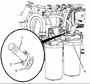
Illustration 2
Typical example
1. Position a new joint (3) on fuel filter base (4).
Note: Ensure correct orientation of the joint.
1. Turn the fuel supply to the “OFF” position.
2. Position fuel priming pump (1) on fuel filter base
(4) and install bolts (2). Tighten the 1/4" bolt to a
torque of 12 N·m (105 lb in). Tighten the 5/16" bolt
to a torque of 25 N·m (221 lb in).
3. Turn the fuel supply to the “ON” position.
4. Remove the air from the fuel system. Refer to
Operation and Maintenance Manual, “Fuel System
- Prime”.
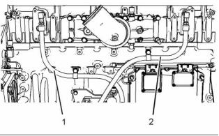
g01380207
Illustration 1
Typical example
2. Remove bolts (2). Remove fuel priming pump (1)
from fuel filter base (4).
3. Remove joint (3).
This document has been printed from SPI². Not for Resale
![]()
![]()
![]()
![]()
![]()
![]()
![]()
![]()
![]()

6
Disassembly and Assembly Section
KENR6906
i02754755
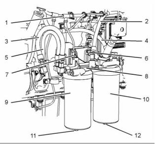
5. Disconnect hose assembly (2). Disconnect hose
assembly (4). Disconnect hose assemblies (3)
and (5). Cap the hose assemblies.
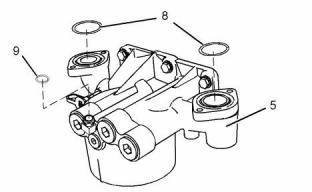
Fuel Filter Base - Remove
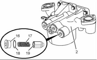
6. Remove fuel filters (9) and (10). Remove the
O-ring seals and the fuel filter elements from the
fuel filters. Refer to Operation and Maintenance
Manual, “Fuel System Primary Filter - Replace”
and refer to Operation and Maintenance Manual,
“Fuel System Secondary Filter - Replace” for more
information.
Removal Procedure
NOTICE
Care must be taken to ensure that fluids are contained
during performance of inspection, maintenance, test-
ing, adjusting and repair of the product. Be prepared to
collect the fluid with suitable containers before open-
ing any compartment or disassembling any compo-
nent containing fluids.
7. Remove bolts (6). Remove fuel filter base (8).
i02754756
Fuel Filter Base - Disassemble
Dispose of all fluids according to local regulations and
mandates.
NOTICE
Keep all parts clean from contaminants.
Disassembly Procedure
Start By:
Contaminants may cause rapid wear and shortened
component life.
a. Remove the fuel filter base. Refer to Disassembly
and Assembly, “Fuel Filter Base - Remove”.
1. Turn the fuel supply to the “OFF” position.
NOTICE
Keep all parts clean from contaminants.
2. Place a suitable container below the fuel filter
base in order to drain the fuel.
Contaminants may cause rapid wear and shortened
component life.
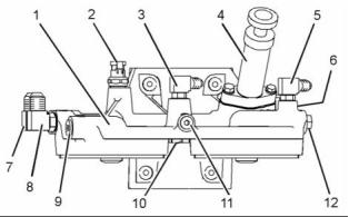
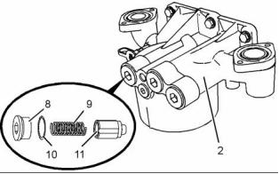
g01380210
Illustration 4
Typical example
g01380208
1. Remove fuel priming pump (4) from fuel filter
base (1). Refer to Disassembly and Assembly,
“Fuel Priming Pump - Remove and Install” for the
correct procedure.
Illustration 3
Typical example
3. Remove plugs (11) and (12). Allow the fuel to
drain.
2. Remove fuel temperature sensor (2) from fuel filter
base (1). Refer to Disassembly and Assembly,
“Fuel Temperature Sensor - Remove and Install”
for the correct procedure.
4. Slide the locking tab into the unlocked position
and disconnect harness assembly (1) from fuel
temperature sensor (7).
This document has been printed from SPI². Not for Resale
![]()
![]()
![]()
![]()
![]()
![]()

![]()
![]()
![]()

KENR6906
7
Disassembly and Assembly Section
3. Remove fuel bypass valve (6) (not shown) from
fuel filter base (1). Remove the O-ring seals from
the fuel bypass valve.
Note: Ensure correct orientation of the connections.
4. Install new O-ring seals to fuel bypass valve (6)
(not shown). Install the fuel bypass valve to fuel
filter base (1). Tighten the fuel bypass valve to a
torque of 35 N·m (26 lb ft).
4. Remove fuel check valve (10) from fuel filter base
(1). Remove the O-ring seals from the fuel check
valve.
5. Install new O-ring seals to fuel check valve (10).
Install the fuel check valve to fuel filter base (1).
Tighten the fuel check valve to a torque of 35 N·m
(26 lb ft).
5. Remove connections (3), (5), (7) and (8) from fuel
filter base (1). Remove the O-ring seals from the
connections.
6. Remove plugs (9), (11) and (12) from fuel filter
base (1). Remove the O-ring seals from the plugs.
6. Install fuel temperature sensor (2) to fuel filter
base (1). Refer to Disassembly and Assembly,
“Fuel Temperature Sensor - Remove and Install”
for the correct procedure.
i02754757
Fuel Filter Base - Assemble
7. Install fuel priming pump (4) to fuel filter base
(1). Refer to Disassembly and Assembly, “Fuel
Priming Pump - Remove and Install” for the
correct procedure.
Assembly Procedure
End By:
a. Install the fuel filter base. Refer to Disassembly
and Assembly, “Fuel Filter Base - Install”.
NOTICE
Keep all parts clean from contaminants.
Contaminants may cause rapid wear and shortened
component life.
i02754758
Fuel Filter Base - Install
1. Ensure that the fuel filter base is clean and free
from damage. If necessary, replace the fuel filter
base.
Installation Procedure
Table 1
Required Tools
Part
Tool
Number
Part Description
Qty
POWERPART
Special Lubricant
A
CV60889
1
NOTICE
Keep all parts clean from contaminants.
Contaminants may cause rapid wear and shortened
component life.
g01380210
Illustration 5
Typical example
2. Install new O-ring seals to plugs (9), (11) and (12).
Install the plugs to fuel filter base (1). Tighten plug
(9) to a torque of 41 N·m (30 lb ft). Tighten plugs
(11) and (12) to a torque of 15 N·m (11 lb ft).
3. Install new O-ring seals to connections (3), (5),
(7) and (8). Install the connections to fuel filter
base (1). Tighten connections (3), (5) and (7) to a
torque of 15 N·m (11 lb ft). Tighten connection (8)
to a torque of 41 N·m (30 lb ft).
This document has been printed from SPI². Not for Resale
![]()
![]()
![]()
![]()
![]()
![]()
8
Disassembly and Assembly Section
KENR6906
i02754760
Fuel Transfer Pump - Remove
Removal Procedure
NOTICE
Care must be taken to ensure that fluids are contained
during performance of inspection, maintenance, test-
ing, adjusting and repair of the product. Be prepared to
collect the fluid with suitable containers before open-
ing any compartment or disassembling any compo-
nent containing fluids.
Dispose of all fluids according to local regulations and
mandates.
NOTICE
g01380208
Keep all parts clean from contaminants.
Illustration 6
Typical example
Contaminants may cause rapid wear and shortened
component life.
1. Position fuel filter base (8) onto the mounting
bracket and install bolts (6). Tighten the bolts to a
torque of 55 N·m (41 lb ft).
1. Turn the fuel supply to the “OFF” position.
2. Install new O-ring seals and new fuel filter
elements to fuel filters (9) and (10). Apply Tooling
(A) to the threads of the fuel filters. Install the fuel
filters to fuel filter base (8). Tighten the fuel filters.
2. Place a suitable container below the fuel transfer
pump in order to catch any fuel that might be
spilled.
Refer to Operation and Maintenance Manual,
“Fuel Filter Primary Filter - Replace” and refer to
Operation and Maintenance Manual, “Fuel Filter
Secondary Filter - Replace” for more information.
3. Install new O-ring seals to plugs (11) and (12).
Install the plugs to fuel filters (9) and (10).
4. Connect hose assemblies (2), (3), (4) and (5).
5. Connect harness assembly (1) to fuel temperature
sensor (7). Slide the locking tab into the locked
position.
6. Turn the fuel supply to the “ON” position.
7. Remove the air from the fuel system. Refer to
Operation and Maintenance Manual, “Fuel System
- Prime”.
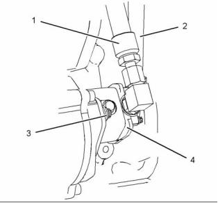
g01380887
Illustration 7
Typical example
3. Disconnect hose assemblies (1) and (2) from fuel
transfer pump (4). Cap the hose assemblies.
4. Remove bolts (3) and remove fuel transfer pump
(4).
This document has been printed from SPI². Not for Resale
![]()
![]()
![]()
![]()
![]()
![]()
![]()
KENR6906
9
Disassembly and Assembly Section
5. Remove the O-ring seal from fuel transfer pump
(4).
7. Remove the air from the fuel system. Refer to
Systems Operation and Maintenance Manual,
“Fuel System - Prime”.
i02754761
Fuel Transfer Pump - Install
i02754762
Electronic Unit Injector -
Remove
Installation Procedure
NOTICE
Keep all parts clean from contaminants.
Removal Procedure
Table 2
Contaminants may cause rapid wear and shortened
component life.
Required Tools
Tool
Part Number
Part Description
Qty
1. Ensure that the fuel transfer pump is clean and
A
27610288
Pry Bar
1
free from damage.
Start By:
a. Remove the rocker shafts. Refer to Disassembly
and Assembly, “Rocker Shaft and Pushrod -
Remove”.
NOTICE
Keep all parts clean from contaminants.
Contaminants may cause rapid wear and shortened
component life.
1. Turn the fuel supply to the OFF position.
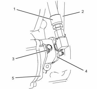
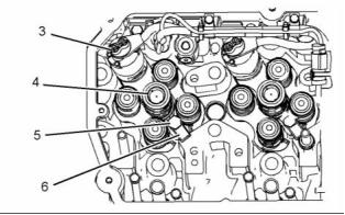
g01416997
Illustration 8
Typical example
2. Lubricate a new O-ring seal with clean engine oil.
Install the O-ring seal to fuel transfer pump (4).
3. Position fuel transfer pump (4) on pump drive (5).
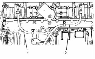
g01411598
Illustration 9
Note: Ensure that the splines on the shaft of the fuel
transfer pump are correctly engaged into the pump
drive.
2. Disconnect hoses (1) and (2) from the fuel filter
base in order to drain fuel from the cylinder head.
4. Install bolts (3). Tighten the bolts to a torque of
55 N·m (41 lb ft).
5. Remove the caps from the hose assemblies.
Connect hose assemblies (1) and (2) to fuel
transfer pump (4).
6. Turn the fuel supply to the “ON” position.
This document has been printed from SPI². Not for Resale
![]()
![]()
![]()
![]()
![]()
![]()
![]()
![]()
10
KENR6906
Disassembly and Assembly Section
i02754763
Electronic Unit Injector - Install
Installation Procedure
Table 3
Required Tools
Tool
B
Part Number
GE50023
GE50024
GE50028
GE50046
Part Description
Tapered Brush
Qty
1
C
Small Bore Brush
Vacuum Pump
1
g01380214
Illustration 10
1
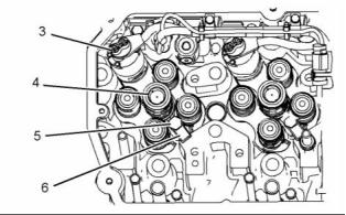
3. Disconnect harness assembly (3) from electronic
Fluid Sampling Bottle
1
unit injector (4).
D
E
Tube
7.9 mm (0.31 inch)
OD
GE50030
1
1
4. Remove bolt (5).
5. Place an identification mark on electronic unit
injector (4) for installation purposes. Each
electronic unit injector must be reinstalled in the
original location in the cylinder head.
27610296
Torque Wrench
NOTICE
Keep all parts clean from contaminants.
6. Use Tooling (A) to pry beneath clamp (6) and free
electronic unit injector (4).
Contaminants may cause rapid wear and shortened
component life.
7. Remove electronic unit injector (4) and clamp (6)
from the cylinder head.
1. Use Tooling (B) and (C) to clean the carbon
deposit from the inside of the electronic unit
injector sleeve.
2. Use Tooling (D) to remove the fuel and oil from
the cylinder. Evacuate as much fuel and oil as
possible from the cylinder before installing the
electronic unit injector. Several evacuations may
be necessary.
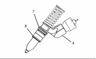
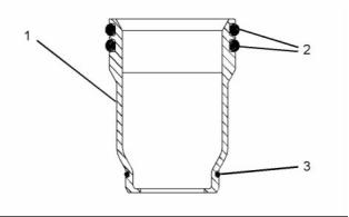
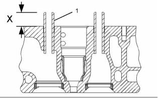
g01380213
Illustration 11
8. Remove O-ring seals (7) and (8) from electronic
unit injector (4).
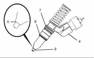
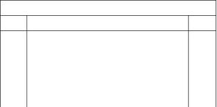
g01380273
Illustration 12
3. Ensure that seat area (X) on electronic unit injector
(4) is clean and free carbon.
This document has been printed from SPI². Not for Resale
![]()
![]()
![]()

![]()
![]()
![]()
KENR6906
11
Disassembly and Assembly Section
4. Install new O-ring seals (7) and (8) to electronic
unit injector (4). Lubricate the O-ring seals with
clean engine oil.
11. Remove the air from the fuel system. Refer to
Operation and Maintenance Manual, “Fuel System
- Prime”.
5. Install a new O-ring seal (9) to electronic unit
End By:
injector (4).
a. Install the rocker shafts. Refer to Disassembly and
Note: O-ring seal (9) should be installed dry.
Assembly, “Rocker Shaft and Pushrod - Install”.
NOTICE
i02754765
Electronic Unit Injector Sleeve
- Remove
If a replacement electronic unit injector is installed, the
calibration code must be programmed into the elec-
tronic control module. Refer to Troubleshooting Guide,
“Injector Trim File” for more information.
Removal Procedure
Table 4
Required Tools
Tool
Part Number
Part Description
Qty
A
GE50021
Injector Sleeve Tool
1
NOTICE
Keep all parts clean from contaminants.
Contaminants may cause rapid wear and shortened
component life.
g01380214
Illustration 13
6. Install clamp (6) to electronic unit injector (4).
Install electronic unit injector (4) into the original
location in the cylinder head.
1. Drain the coolant from the cooling system into
a suitable container for storage or for disposal.
Refer to Operation and Maintenance Manual,
“Cooling System Coolant - Change”.
7. Install bolt (5). Tighten the bolt to a torque of
55 N·m (41 lb ft).
2. Remove the electronic unit injectors. Refer to
Disassembly and Assembly, “Electronic Unit
Injector - Remove”.
8. Connect harness assembly (3) to electronic unit
injector (4). Use Tooling (E) to tighten the nuts to a
torque of 2.5 N·m (22 lb in).
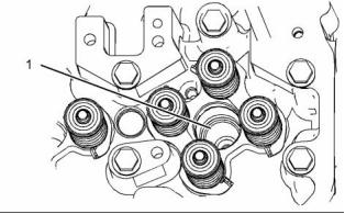
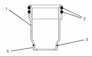
g01391954
Illustration 15
g01411598
Illustration 14
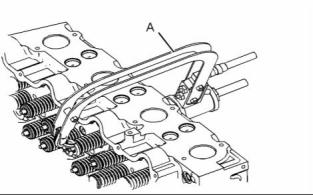
3. Install Tooling (A) into electronic unit injector
sleeve (1).
9. Connect hoses (1) and (2) to the fuel filter base.
10. Turn the fuel supply to the “ON” position.
This document has been printed from SPI². Not for Resale
![]()
![]()
![]()
![]()
![]()
![]()
![]()
![]()
12
KENR6906
Disassembly and Assembly Section
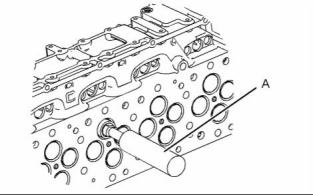
4. Tighten the nut on Tooling (A) until electronic unit
injector sleeve (1) is pulled free from the cylinder
head.
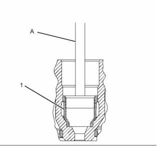
g01043165
Illustration 17
g01393881
Illustration 16
5. Remove O-ring seals (2) and O-ring seal (3) from
electronic unit injector sleeve (1).
i02754766
Electronic Unit Injector Sleeve
- Install
Installation Procedure
Table 5
Required Tools
Tool
Part Number
GE50021
GE50023
GE50024
GE50022
CV60893
Part Description
Injector Sleeve Tool
Tapered Brush
Qty
1
g01393891
Illustration 18
A
1
2. Install new O-ring seals (2) and (3) to electronic
unit injector sleeve (1).
B
C
Small Bore Brush
End Brush
1
1
3. Install electronic unit injector sleeve (1) to Tooling
(A).
Retaining Compound
1
4. Apply a small continuous bead of Tooling (C) to
NOTICE
surface (X) of electronic unit injector sleeve (1).
Keep all parts clean from contaminants.
5. Lubricate O-ring seals (2) with clean engine oil.
Contaminants may cause rapid wear and shortened
component life.
6. Position electronic unit injector sleeve (1) and
Tooling (A) in the cylinder head. Use care not to
damage O-ring seals (2) and (3).
1. Use Tooling (B) to clean the bore in the cylinder
head for the electronic unit injector sleeve.
7. Use Tooling (A) and a soft faced hammer to install
electronic unit injector sleeve (1) to the cylinder
head.
NOTICE
Ensure that the electronic unit injector sleeve and the
cylinder head bore are completely free of oil, dirt, and
sealant debris.
Note: Ensure that the electronic unit injector sleeve
is properly seated in the cylinder head.
This document has been printed from SPI². Not for Resale
![]()
![]()
![]()
![]()
![]()
![]()
![]()
![]()
KENR6906
13
Disassembly and Assembly Section
8. Install the electronic unit injectors. Refer to
Disassembly and Assembly, “Electronic Unit
Injector - Install”.
Installation Procedure
9. Fill the cooling system with coolant. Refer to
Operation and Maintenance, “Cooling System
Coolant - Change”.
i02754770
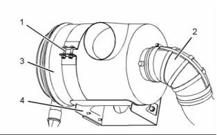
Air Cleaner - Remove and
Install
g01380888
Removal Procedure
Illustration 20
Typical example
NOTICE
Keep all parts clean from contaminants.
1. If necessary, position mounting bracket (4) on the
cylinder head and install the bolts that secure
the mounting bracket. Tighten theM12 bolts to a
torque of 100 N·m (74 lb ft). Tighten the 3/8" bolts
to a torque of 47 N·m (35 lb ft).
Contaminants may cause rapid wear and shortened
component life.
2. Position air cleaner (3) on mounting bracket (4).
Ensure the correct orientation of the air cleaner.
3. Install fasteners (1). Tighten the fasteners to a
torque of 55 N·m (41 lb ft).
4. Connect hose (2) and tighten the hose clamp
securely.
i02754771
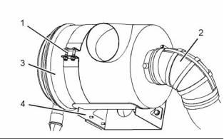
Turbocharger - Remove
g01380888
Illustration 19
Typical example
Removal Procedure
1. Loosen the hose clamp and disconnect hose (2).
Start By:
2. Remove fasteners (1) and remove air cleaner (3)
from mounting bracket (4). Note the orientation
of the air cleaner.
a. Remove the exhaust elbow. Refer to Disassembly
and Assembly, “Exhaust Elbow - Remove and
Install”.
3. If necessary, remove the bolts that secure
mounting bracket (4) and remove the mounting
bracket.
NOTICE
Care must be taken to ensure that fluids are contained
during performance of inspection, maintenance, test-
ing, adjusting and repair of the product. Be prepared to
collect the fluid with suitable containers before open-
ing any compartment or disassembling any compo-
nent containing fluids.
Dispose of all fluids according to local regulations and
mandates.
This document has been printed from SPI². Not for Resale
![]()
![]()
![]()
![]()
![]()
![]()
![]()
14
KENR6906
Disassembly and Assembly Section
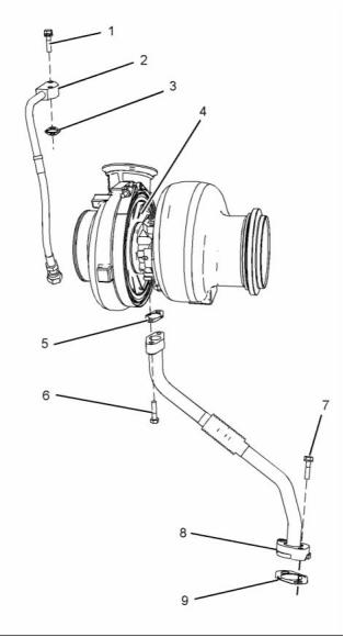
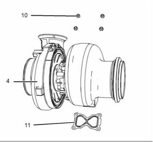
c. Remove tube assembly (2) and joint (3) from
turbocharger (4).
NOTICE
Keep all parts clean from contaminants.
3. Follow Steps 3 through 3.c in order to remove the
tube assembly for the oil drain to the turbocharger.
Contaminants may cause rapid wear and shortened
component life.
a. Remove bolts (6) and (7).
b. Remove tube assembly (8).
c. Remove joints (5) and (9).
1. Disconnect the air hoses from the turbocharger
inlet and from the turbocharger outlet.
4. Attach a suitable lifting device to turbocharger (4).
The weight of the turbocharger is approximately
32 kg (71 lb).
g01382805
Illustration 22
Typical example
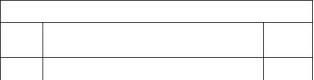
5. Remove nuts (10). Use the lifting device to remove
turbocharger (4) from the exhaust manifold.
6. Remove gasket (11).
i02754772
Turbocharger - Install
g01380889
Illustration 21
Installation Procedure
Typical example
Table 6
2. Follow Steps 2.a through 2.c in order to remove the
Required Tools
Part
tube assembly for the oil feed to the turbocharger.
a. Disconnect tube assembly (2) from the engine
oil filter base.
Tool
Number
Part Description
Qty
A
CV60889
Anti-Seize Compound
1
b. Remove bolts (1).
This document has been printed from SPI². Not for Resale
![]()
![]()
![]()
![]()
![]()
KENR6906
15
Disassembly and Assembly Section
NOTICE
Keep all parts clean from contaminants.
Contaminants may cause rapid wear and shortened
component life.
1. Ensure that all mating surfaces are clean and free
from damage.
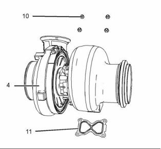
g01382805
Illustration 23
Typical example
2. Position a new gasket (11) on the exhaust
manifold.
3. Attach a suitable lifting device to turbocharger
(4). The weight of turbocharger is approximately
32 kg (71 lb). Use the lifting device to install the
turbocharger to the exhaust manifold.
g01413397
Illustration 24
4. Apply Tooling (A) to the threads of the exhaust
Typical example
manifold studs.
6. Follow Steps 6.a through 6.c in order to install the
tube assembly for the oil drain to the turbocharger.
5. Install nuts (10). Tighten the nuts to a torque of
55 N·m (41 lb ft).
a. Place a new joint (9) and tube assembly (8) in
position and install bolts (7) finger tight.
If a new turbocharger is installed, loosen the
V-band clamps and rotate the bearing housing and
the compressor housing to the correct positions.
b. Position a new joint (5) between turbocharger
(4) and tube assembly (8). Install bolts (6)
finger tight.
c. Tighten bolts (6) and (7) to a torque of 28 N·m
(21 lb ft).
7. Lubricate the bearings of turbocharger (4) with
clean engine oil through oil inlet port (X). Rotate
the shaft of the turbocharger in order to distribute
the lubricant.
This document has been printed from SPI². Not for Resale
![]()
![]()
![]()
![]()
![]()
16
KENR6906
Disassembly and Assembly Section
8. Follow Steps 8.a through 8.c in order to install the
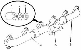
Note: Remove the manifolds as one assembly.
tube assembly for the oil feed to the turbocharger.
3. Remove the exhaust manifold gaskets.
a. Place a new joint (3) and tube assembly (2) in
position on turbocharger (4).
4. Remove exhaust manifolds (4) and (6) from
exhaust manifold (5).
b. Install bolts (1). Tighten the bolts to a torque of
28 N·m (21 lb ft).
5. If necessary, remove the taperlock studs from the
cylinder head.
c. Connect tube assembly (2) to the engine oil
filter base.
Installation Procedure
9. Connect the air hoses to the turbocharger inlet
and the turbocharger outlet.
Table 7
Required Tools
If a new turbocharger was installed, tighten the
V-band clamp for the exhaust housing to 13.5 N·m
(120 lb in). Tighten the V-band clamp for the
compressor housing to 18 N·m (160 lb in).
Tool
Part Number
Part Description
Qty
A
CV60889
Anti-Seize Compound
1
NOTICE
Keep all parts clean from contaminants.
End By:
a. Install the exhaust elbow. Refer to Disassembly
and Assembly, “Exhaust Elbow - Remove and
Install”
Contaminants may cause rapid wear and shortened
component life.
1. If necessary, install the taperlock studs to the
cylinder head. Tighten the taperlock studs to a
torque of 35 N·m (26 lb ft).
i02754773
Exhaust Manifold - Remove
and Install
Removal Procedure
Start By:
a. Remove the turbocharger. Refer to Disassembly
and Assembly, “Turbocharger - Remove”.
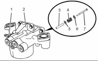
g01380890
Illustration 26
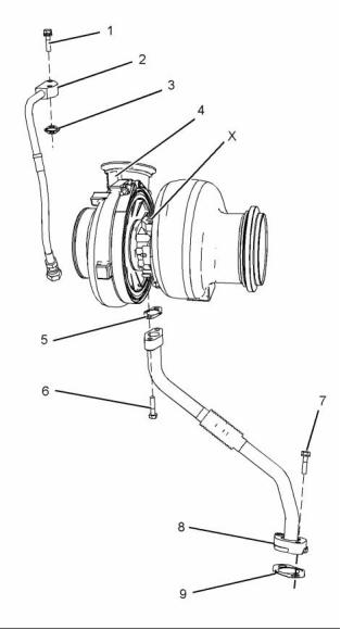
2. Assemble exhaust manifolds (4), (5) and (6).
3. Position the exhaust manifold gaskets onto the
taperlock studs.
4. Install the assembly of the exhaust manifolds to
the cylinder head.
Note: Ensure that the holes in exhaust manifolds are
centralized with the taperlock studs.
g01380890
Illustration 25
5. Apply Tooling (A) to the threads of the taperlock
studs. Install spacers (1), washers (2) and nuts (3).
1. Remove nuts (3), washers (2) and spacers (1).
2. Remove exhaust manifolds (4), (5) and (6).
This document has been printed from SPI². Not for Resale
![]()
![]()
![]()
![]()
![]()
![]()
KENR6906
17
Disassembly and Assembly Section
Installation Procedures
NOTICE
Keep all parts clean from contaminants.
Contaminants may cause rapid wear and shortened
component life.
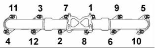
g01380891
Illustration 27
1. Thoroughly clean the exhaust elbow and the outlet
of the turbocharger. Inspect the components for
wear or damage. Replace any components that
are worn or damaged.
6. Tighten the nuts to a torque of 55 N·m (41 lb ft) in
a numerical sequence that is shown in Illustration
27.
End By:
a. Install the turbocharger. Refer to Disassembly and
Assembly, “Turbocharger - Install”.
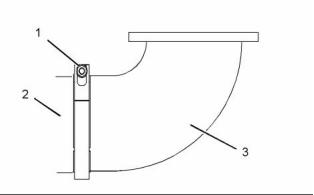
i02754774
Exhaust Elbow - Remove and
Install
Removal Procedure
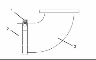
g01382827
Illustration 29
NOTICE
Keep all parts clean from contaminants.
2. Position clamp (1) and install exhaust elbow (3)
to turbocharger (2). Ensure correct orientation of
the clamp.
Contaminants may cause rapid wear and shortened
component life.
3. Tighten clamp (1) to a torque of 14 N·m (10 lb ft).
i02763449
Inlet Manifold - Remove and
Install
Removal Procedure
NOTICE
Keep all parts clean from contaminants.
Contaminants may cause rapid wear and shortened
component life.
g01382827
Illustration 28
1. Loosen clamp (1).
2. Remove exhaust elbow (3) and clamp (1) from
turbocharger (2).
This document has been printed from SPI². Not for Resale
![]()
![]()
![]()
![]()
![]()
![]()
![]()
![]()
![]()
![]()
18
KENR6906
Disassembly and Assembly Section
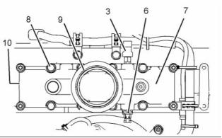
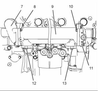
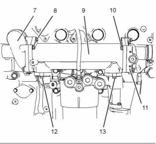
6. Remove fasteners (8). Note the position of the
brackets that are retained by the fasteners.
7. Remove inlet manifold (7) from the cylinder, , head.
8. Remove gasket (10) (not shown).
9. If necessary, remove inlet manifold pressure
sensor (3) and remove inlet manifold temperature
sensor (6) from inlet manifold (7). Refer to
Disassembly and Assembly, “Inlet Manifold
Pressure Sensor - Remove and Install” and
Disassembly and Assembly, “Inlet Manifold
Temperature Sensor - Remove and Install” for
more information.
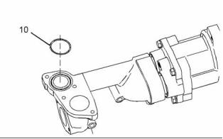
Installation Procedure
NOTICE
Keep all parts clean from contaminants.
g01383308
Illustration 30
Contaminants may cause rapid wear and shortened
component life.
Typical example
1. Loosen the hose clamps and disconnect air hose
(1) from connection (2).
1. Ensure that all mating surfaces are clean and free
from debris.
2. Slide the locking tab into the unlocked position
and disconnect harness assembly (4) from inlet
manifold pressure sensor (3).
3. Slide the locking tab into the unlocked position
and disconnect harness assembly (4) from inlet
manifold temperature sensor (6).
4. Loosen clamp (5) and remove connection (2) from
inlet manifold (7).
Note: Make a temporary mark in order to show the
orientation of the connection.
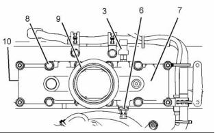
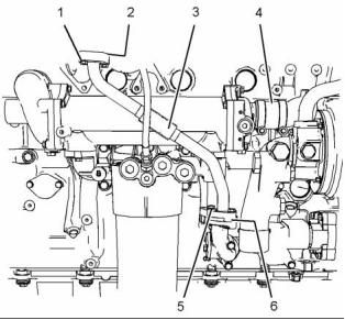
g01384161
Illustration 32
Typical example
2. Place a new gasket (10) (not shown) in position
on inlet manifold (7).
3. Position inlet manifold (7) on the cylinder head.
4. Install fasteners (8). Ensure that the brackets that
are retained by the fasteners are installed in the
correct positions.
5. Tighten fasteners (8) to a torque of 55 N·m
(41 lb ft).
g01384161
Illustration 31
Typical example
6. Install a new O-ring seal (9) to inlet manifold (7).
5. Remove O-ring seal (9) from inlet manifold (7).
This document has been printed from SPI². Not for Resale
![]()
![]()

![]()
![]()
![]()
![]()
KENR6906
19
Disassembly and Assembly Section
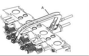
i02754775
Inlet and Exhaust Valve
Springs - Remove and Install
Removal Procedure
Table 8
Required Tools
Tool
A
Part Number
CH11148
Part Description
Engine Turning Tool
Qty
1
B
CVT0003
Valve Spring Compressor
1
Start By:
a. Remove the electronic unit injectors. Refer to
Disassembly and Assembly, “Electronic Unit
Injector - Remove”.
g01383308
Illustration 33
Typical example
7. Install connection (2) and clamp (5) to inlet
manifold (7). Tighten the clamp to a torque of
14 N·m (10 lb ft).
NOTICE
Keep all parts clean from contaminants.
Contaminants may cause rapid wear and shortened
component life.
Note: Ensure correct orientation of the connection.
8. If necessary, install inlet manifold pressure sensor
(3) and install inlet manifold temperature sensor
(6) to inlet manifold (7). Refer to Disassembly
and Assembly, “Inlet Manifold Pressure Sensor
- Remove and Install” and Disassembly and
Assembly, “Inlet Manifold Temperature Sensor -
Remove and Install” for more information.
Note: The following procedure should be adopted in
order to remove the valve springs when the cylinder
head is installed to the engine. Refer to Disassembly
and Assembly, “Inlet and Exhaust Valves - Remove
and Install” for the procedure to remove the valve
springs from a cylinder head that has been removed
from the engine.
9. Connect harness assembly (4) to inlet manifold
pressure sensor (3) and slide the locking tab into
the locked position.
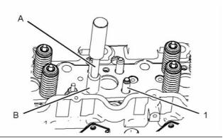
1. Use Tooling (A) to position the appropriate piston
at the top center position before the valve spring
is removed.
10. Connect harness assembly (4) to inlet manifold
temperature sensor (6) and slide the locking tab
into the locked position.
Note: Failure to ensure that the piston is at the top
center position may allow the valve to drop into the
cylinder bore.
11. Connect air hose (1) to connection (2) and tighten
the hose clamps securely.
NOTICE
Do not turn the crankshaft while the valve springs are
removed.
Note: Valve springs must be replaced in pairs for the
inlet valves or the exhaust valves of each cylinder. If
all valve springs require replacement the procedure
can be carried out on two cylinders at the same time.
The procedure can be carried out on the following
pairs of cylinders. 1 with 6, 2 with 5, and 3 with 4.
Ensure that all of the valve springs are installed
before changing from one pair of cylinders to another
pair of cylinders.
This document has been printed from SPI². Not for Resale
![]()
![]()
![]()
![]()
![]()
![]()
20
KENR6906
Disassembly and Assembly Section
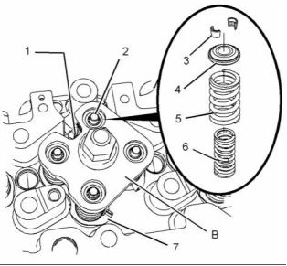
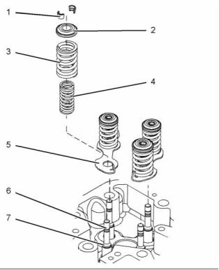
8. Remove spring seats (7) from the valve guides.
g01411612
Illustration 35
9. If necessary, remove valve stem seals (8).
Installation Procedure
g01380893
Illustration 34
Table 9
Required Tools
Tool
Part Number
Part Description
Qty
Personal injury can result from being struck by
parts propelled by a released spring force.
B
CVT0003
Valve Spring Compressor
1
Make sure to wear all necessary protective equip-
ment.
NOTICE
Keep all parts clean from contaminants.
Follow the recommended procedure and use all
recommended tooling to release the spring force.
Contaminants may cause rapid wear and shortened
component life.
NOTICE
1. Inspect the valve springs for damage and for the
correct length. Refer to Specifications, “Cylinder
Head Valves ”.
Plug the apertures for the push rods in the cylinder
head in order to prevent the entry of loose parts into
the engine.
2. Lubricate the valve stems with clean engine oil.
2. Position electronic unit injector clamp (1) on
Tooling (B). Install Tooling (B) into the electronic
unit injector sleeve. Tighten the bolt on the
electronic unit injector clamp in order to secure
Tooling (B).
3. Tighten the nut on Tooling (B) until valve keepers
(3) are loose on valves (2).
4. Remove valve keepers (3).
5. Loosen the nut in order to release the pressure
on Tooling (B). Remove electronic unit injector
clamp (1) and Tooling (B) from the electronic unit
injector sleeve.
g01411612
Illustration 36
6. Remove valve rotators (4).
3. If necessary, install new valve stem seals (8).
7. Remove outer valve springs (5) and inner valve
springs (6).
This document has been printed from SPI². Not for Resale
![]()
![]()
![]()
![]()
![]()
![]()
![]()
![]()
![]()
![]()

KENR6906
21
Disassembly and Assembly Section
9. Loosen the nut in order to release the pressure
on Tooling (B). Remove electronic unit injector
clamp (1) and Tooling (B) from the electronic unit
injector sleeve.
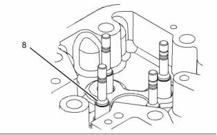
10. Ensure that all of the valves are secured in place
by valve springs, valve rotators and valve keepers.
Rotate the crankshaft through approximately 45
degrees in order to clear the valves from the
piston. Lightly strike the top of the valves with a
soft faced hammer in order to ensure that the
valve keepers are properly installed.
End By:
a. Install the electronic unit injectors. Refer to
Disassembly and Assembly, “Electronic Unit
Injector - Install”.
i02754776
Inlet and Exhaust Valves -
Remove and Install
g01380893
Illustration 37
Improper assembly of parts that are spring loaded
can cause bodily injury.
Removal Procedure
To prevent possible injury, follow the established
assembly procedure and wear protective equip-
ment.
Table 10
Required Tools
Part
4. Install spring seats (7).
Tool
Number
Part Description
Qty
A
-
Valve Spring Compressor
1
5. Install inner valve springs (6) and outer valve
springs (5).
Start By:
6. Position valve rotators (4) on the valve springs.
a. Remove the cylinder head. Refer to Disassembly
and Assembly, “Cylinder Head - Remove”.
7. Position electronic unit injector clamp (1) on
Tooling (B). Install Tooling (B) into the electronic
unit injector sleeve. Tighten the bolt on the
electronic unit injector clamp in order to secure
Tooling (B).
NOTICE
Keep all parts clean from contaminants.
Contaminants may cause rapid wear and shortened
component life.
The valve spring keepers can be thrown from
the valve when the valve spring compressor is
released. Ensure that the valve spring keepers
are properly installed on the valve stem. To help
prevent personal injury, keep away from the front
of the valve spring keepers and valve springs
during the installation of the valves.
8. Tighten the nut on Tooling (B) in order to compress
the valve springs. Install valve keepers (3).
This document has been printed from SPI². Not for Resale
![]()
![]()

![]()
![]()
![]()
![]()
![]()
![]()
22
KENR6906
Disassembly and Assembly Section
2. Carefully remove Tooling (A).
3. Remove valve rotator (2).
4. Remove outer valve spring (3) and inner valve
spring (4).
5. Repeat Steps 1 through 4 in order to remove the
remaining valve springs.
6. Remove spring seats (5).
7. Remove valve stem seals (7).
8. Remove valves (6) from the cylinder head.
g01395727
Illustration 38
Typical example
Installation Procedure
Table 11
Required Tools
Part
Tool
Number
Part Description
Qty
A
-
Valve Spring Compressor
1
NOTICE
Keep all parts clean from contaminants.
Contaminants may cause rapid wear and shortened
component life.
1. Inspect the valve springs for the correct length.
Refer to Specifications, “Cylinder Head Valves ”
for more information.
Note: Valve springs must be replaced in pairs for the
inlet valve or the exhaust valve of each cylinder.
2. Inspect the valves. Refer to Specifications,
“Cylinder Head Valves” for more information.
g01392788
Illustration 39
Personal injury can result from being struck by
parts propelled by a released spring force.
Make sure to wear all necessary protective equip-
ment.
Follow the recommended procedure and use all
recommended tooling to release the spring force.
1. Install Tooling (A) and compress the valve springs.
Remove valve keepers (1).
This document has been printed from SPI². Not for Resale
![]()
![]()
![]()
![]()
![]()
![]()
![]()
KENR6906
23
Disassembly and Assembly Section
6. Install inner valve spring (4) and outer valve spring
(3).
7. Position valve rotator (2) on the valve springs.
8. Use Tooling (A) to compress the valve springs.
Install valve keepers (1).
9. Repeat Steps 6 through 8 in order to install the
remaining valve keepers.
The valve spring keepers can be thrown from
the valve when the valve spring compressor is
released. Ensure that the valve spring keepers
are properly installed on the valve stem. To help
prevent personal injury, keep away from the front
of the valve spring keepers and valve springs
during the installation of the valves.
10. Carefully remove Tooling (A). Lightly strike the top
of the valve with a soft faced hammer in order to
ensure that valve keepers (1) are properly seated.
End By:
g01392788
Illustration 40
a. Install the cylinder head. Refer to Disassembly
and Assembly, “Cylinder Head - Install”.
i02754778
Inlet and Exhaust Valve Guides
- Remove and Install
Removal Procedure
Table 12
Required Tools
g01395727
Illustration 41
Tool
Part Number
Part Description
Qty
Typical example
A
CVT0001
Valve Guide Driver
1
Start By:
The valve keepers can be thrown from the valve
when the valve spring compressor is released. En-
sure that the valve keepers are properly installed
on the valve stem. To help prevent personal injury,
keep away from the front of the valve keepers and
valve springs during the installation of the valves.
a. Remove the inlet and exhaust valves. Refer to
Disassembly and Assembly, “Inlet and Exhaust
Valves - Remove and Install”.
NOTICE
Keep all parts clean from contaminants.
3. Lubricate valves (6) with clean engine oil. Install
the valves to the cylinder head.
Contaminants may cause rapid wear and shortened
component life.
4. Install valve stem seals (7) to valves (6).
5. Install spring seats (5) to the cylinder head.
This document has been printed from SPI². Not for Resale
![]()
![]()

![]()
![]()
![]()
![]()
![]()
![]()
![]()
24
KENR6906
Disassembly and Assembly Section
g01383260
g01383261
Illustration 42
Illustration 44
1. Use Tooling (A) and a hammer in order to remove
the valve guides from the cylinder head.
2. Use Tooling (A) and Tooling (B) to install valve
guides (1) in the cylinder head.
Installation Procedure
Note: Tooling (B) must be used in order to install the
valve guides to the correct height.
Table 13
Height (X) from the top of the valve guide to the
cylinder head surface ................ 35.00 ± 0.50 mm
(1.378 ± 0.020 inch)
Required Tools
Tool
A
Part Number
CVT0001
Part Description
Valve Guide Driver
Valve Guide Collar
Qty
1
For more information, refer to Specifications,
“Cylinder Head Valves”.
B
CVT0002
1
End By:
NOTICE
Keep all parts clean from contaminants.
a. Install the inlet and exhaust valves. Refer to
Disassembly and Assembly, “Inlet and Exhaust
Valves - Remove and Install”.
Contaminants may cause rapid wear and shortened
component life.
i02754779
Engine Oil Filter Base -
Remove
1. Lubricate the parent bores for the valve guides in
the cylinder head with clean engine oil.
Removal Procedure
NOTICE
Keep all parts clean from contaminants.
Contaminants may cause rapid wear and shortened
component life.
g01383265
Illustration 43
This document has been printed from SPI². Not for Resale
![]()
![]()
![]()
![]()
![]()
![]()
![]()
![]()
KENR6906
25
Disassembly and Assembly Section
NOTICE
Care must be taken to ensure that fluids are contained
during performance of inspection, maintenance, test-
ing, adjusting and repair of the product. Be prepared to
collect the fluid with suitable containers before open-
ing any compartment or disassembling any compo-
nent containing fluids.
Dispose of all fluids according to local regulations and
mandates.
1. Place a suitable container below the engine oil
filter base in order to drain the engine oil.
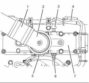
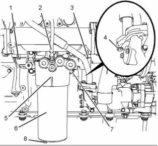
g01401581
Illustration 46
9. Remove O-ring seals (8) and O-ring seal (9) from
engine oil filter base (5).
g01404137
Illustration 47
10. Remove O-ring seal (10) from the engine oil
pump.
g01396094
Illustration 45
2. Remove plug (8). Allow the engine oil to drain.
i02754781
Engine Oil Filter Base -
Disassemble
3. Remove engine oil filter (6) from engine oil filter
base (5). Remove the O-ring seal and remove the
filter element from the engine oil filter. Refer to
Operation and Maintenance Manual, “Engine Oil
and Filter - Change” for more information.
4. Disconnect hose assembly (2) from engine oil
filter base (5).
Disassembly Procedure
5. Remove bolts (1) and (3).
Start By:
6. Remove bolts (4) in order to disconnect the tube
assembly from the engine oil pump.
a. Remove the engine oil filter base. Refer to
Disassembly and Assembly, “Engine Oil Filter
Base - Remove”.
7. Support the weight of the engine oil cooler. The
engine oil cooler weighs approximately 23 kg
(50 lb).
NOTICE
Keep all parts clean from contaminants.
8. Remove engine oil filter base (5) and remove the
joint.
Contaminants may cause rapid wear and shortened
component life.
This document has been printed from SPI². Not for Resale
![]()
![]()
![]()
![]()
![]()
![]()
![]()
![]()
26
KENR6906
Disassembly and Assembly Section
b. Remove spring (9).
c. Remove plunger (11).
Personal injury can result from being struck by
parts propelled by a released spring force.
Make sure to wear all necessary protective equip-
ment.
Follow the recommended procedure and use all
recommended tooling to release the spring force.
g01396108
Illustration 50
4. Follow Steps 4.a through 4.c in order to remove
the oil cooler bypass valve.
a. Remove plug (12) from engine oil filter base
(2). Remove O-ring seal (13) from plug (12).
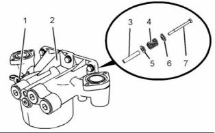
g01380571
Illustration 48
b. Remove spring assembly (14).
c. Remove plunger (15).
1. If necessary, remove oil sampling valve (1) from
engine oil filter base (2). Remove the O-ring seal
from the oil sampling valve.
2. Follow Steps 2.a and 2.b in order to remove the
high pressure relief valve.
a. Remove bolt (7) from engine oil filter base (2).
b. Remove cap (6), spring (4), seat (5) and sleeve
(3) from engine oil filter base (2).
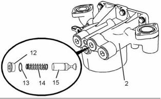
g01396110
Illustration 51
5. Follow Steps 5.a through 5.c in order to remove
the oil pump bypass valve.
a. Remove plug (16) from engine oil filter base
(2). Remove O-ring seal (18) from plug (16).
b. Remove spring (17).
c. Remove plunger (19).
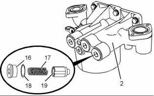
g01396109
Illustration 49
3. Follow Steps 3.a through 3.c in order to remove
the oil filter bypass valve.
a. Remove plug (8) from engine oil filter base (2).
Remove O-ring seal (10) from plug (8).
This document has been printed from SPI². Not for Resale
![]()
![]()
![]()
![]()
![]()

![]()
![]()
KENR6906
27
Disassembly and Assembly Section
i02754782
Engine Oil Filter Base -
Assemble
Assembly Procedure
NOTICE
Keep all parts clean from contaminants.
Contaminants may cause rapid wear and shortened
component life.
g01396108
Illustration 53
3. Follow Steps 3.a through 3.d in order to install the
oil cooler bypass valve.
Improper assembly of parts that are spring loaded
can cause bodily injury.
a. Lubricate spring assembly (14), and plunger
(15) with clean engine oil.
To prevent possible injury, follow the established
assembly procedure and wear protective equip-
ment.
b. Install spring assembly (14), and plunger (15)
into engine oil filter base (2).
c. Install a new O-ring seal (13) to plug (12).
1. Inspect the components for wear or damage.
Replace any components that are worn or
damaged.
d. Install plug (12) to engine oil filter base (2).
Tighten the plug to a torque of 100 N·m
(74 lb ft).
g01396110
Illustration 52
g01396109
Illustration 54
2. Follow Steps 2.a through 2.d in order to install the
oil pump bypass valve.
4. Follow Steps 4.a through 4.d in order to install the
oil filter bypass valve.
a. Lubricate plunger (19) and spring (17) with
clean engine oil.
a. Lubricate plunger (11) and spring (9) with clean
engine oil.
b. Install plunger (19) and spring (17) into engine
oil filter base (2).
b. Install plunger (11) and spring (9) into engine
oil filter base (2).
c. Install a new O-ring seal (18) to plug (16).
c. Install a new O-ring seal (10) to plug (8).
d. Install plug (16) to engine oil filter base (2).
Tighten the plug to a torque of 100 N·m
(74 lb ft).
d. Install plug (8) to engine oil filter base (2).
Tighten the plug to a torque of 100 N·m
(74 lb ft).
This document has been printed from SPI². Not for Resale
![]()
![]()
![]()
![]()
![]()
![]()
![]()

![]()
28
KENR6906
Disassembly and Assembly Section
NOTICE
Keep all parts clean from contaminants.
Contaminants may cause rapid wear and shortened
component life.
1. Ensure that the engine oil filter base is clean and
free from damage. Clean the mating surfaces of
the engine oil pump and the cylinder block.
g01380571
Illustration 55
5. Follow Steps 5.a and 5.b in order to install the
high pressure relief valve.
a. Lubricate sleeve (3), seat (5), spring (4) and
cap (6) with clean engine oil.
b. Install sleeve (3), seat (5), spring (4), cap (6)
and bolt (7) to engine oil filter base (2). Tighten
the bolt to a torque of 12 N·m (105 lb in).
g01404137
Illustration 56
6. If necessary, install a new O-ring seal to oil
sampling valve (1) and install the oil sampling
valve to engine oil filter base (2). Tighten the oil
sampling valve to a torque of 24 N·m (18 lb ft).
2. Install a new O-ring seal (10) to the engine oil
pump.
End By:
a. Install the engine oil filter base. Refer to
Disassembly and Assembly, “Engine Oil Filter
Base - Install”.
i02754783
Engine Oil Filter Base - Install
Installation Procedure
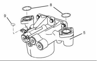
g01401581
Illustration 57
Table 14
3. Install new O-ring seals (8) and (9) to engine oil
filter base (5).
Required Tools
Part
Tool
Number
Part Description
Qty
POWERPART
Threadlock and Nutlock
A
21820117
1
POWERPART
Special Lubricant
B
CV60889
1
This document has been printed from SPI². Not for Resale
![]()
![]()
![]()
![]()
![]()

![]()
![]()
KENR6906
29
Disassembly and Assembly Section
i02754784
Engine Oil Cooler - Remove
Removal Procedure
NOTICE
Keep all parts clean from contaminants.
Contaminants may cause rapid wear and shortened
component life.
NOTICE
Care must be taken to ensure that fluids are contained
during performance of inspection, maintenance, test-
ing, adjusting and repair of the product. Be prepared to
collect the fluid with suitable containers before open-
ing any compartment or disassembling any compo-
nent containing fluids.
g01396094
Illustration 58
4. Apply Tooling (A) to the threads of bolts (7).
Dispose of all fluids according to local regulations and
mandates.
5. Support the weight of the engine oil cooler. The
engine oil cooler weighs approximately 23 kg
(50 lb).
1. Drain the coolant from the cooling system into
a suitable container for storage or for disposal.
Refer to Operation and Maintenance Manual,
“Cooling System Coolant - Change”.
6. Position a new joint and engine oil filter base (5)
on the cylinder block.
7. Install bolts (7). Tighten the bolts to a torque of
55 N·m (41 lb ft).
8. Connect the tube assembly to the engine oil pump
and install bolts (4). Tighten the bolts to a torque
of 28 N·m (21 lb ft).
9. Install bolts (1) and (3). Tighten the bolts to a
torque of 28 N·m (21 lb ft).
10. Connect hose assembly (2).
11. Install a new O-ring seal and a new filter element
to engine oil filter (6). Apply Tooling (B) to the
threads of the engine oil filter. Install the engine oil
filter to engine oil filter base (5). Use a suitable
tool with a 1/2" square drive in order to tighten the
engine oil filters.
Refer to Operation and Maintenance Manual,
“Engine Oil and Filter - Change” for more
information.
g01401585
Illustration 59
2. Loosen the hose clamps and slide hose (4)
forward in order to disconnect the hose from the
engine oil cooler.
Install a new O-ring seal to plug (8). Install the
plug to fuel filter (6).
3. Follow Step 3.a through Step 3.c in order to
remove tube assembly (3).
a. Remove bolts (1) and joint (2) (not shown).
This document has been printed from SPI². Not for Resale
![]()
![]()

![]()
![]()
![]()
![]()
![]()

30
KENR6906
Disassembly and Assembly Section
b. Remove bolts (5) and tube assembly (3).
c. Remove O-ring seal (6) (not shown) from tube
assembly (3).
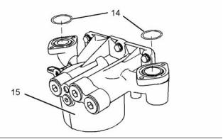
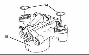
g01401595
Illustration 61
11. Remove O-ring seals (14) from engine oil filter
base (15).
i02754785
Engine Oil Cooler - Install
g01403771
Illustration 60
Installation Procedure
4. Attach a suitable lifting device to engine oil cooler
(9) in order to support the weight of the engine oil
cooler. The engine oil cooler weighs approximately
23 kg (50 lb).
NOTICE
Keep all parts clean from contaminants.
Contaminants may cause rapid wear and shortened
component life.
5. Remove bolts (12) and bolts (13).
6. Remove bolts (10).
1. Ensure that the oil cooler is clean and free from
damage or restriction. Clean the mating surfaces
of the cooler connections and the engine oil filter
base.
Note: The rear bolt needs only to be loosened in
order to remove connection (11).
7. Remove connection (11). Remove the O-ring seal
from the connection.
8. Remove bolts (8).
9. Carefully remove engine oil cooler (9).
10. Remove the O-ring seal from connection (7).
g01401595
Illustration 62
2. Install new O-ring seals (14) to engine oil filter
base (15).
This document has been printed from SPI². Not for Resale
![]()
![]()
![]()
![]()
![]()
![]()
KENR6906
31
Disassembly and Assembly Section
g01403771
g01401585
Illustration 63
Illustration 64
3. Install new O-ring seals to connections (7) and
(11).
9. Follow Step 9.a through Step 9.d in order to install
tube assembly (3).
4. Attach a suitable lifting device to engine oil
cooler (9). The weight of the engine oil cooler is
approximately 23 kg (50 lb).
a. Install a new O-ring seal (6) (not shown) to tube
assembly (3).
b. Install a new joint (2) and bolts (1) to tube
5. Position engine oil cooler (9) on the engine oil
filter base.
assembly (3).
c. Position tube assembly (3) on the engine and
tighten bolts (1) finger tight.
6. Install bolts (8). Tighten the bolts to a torque of
28 N·m (21 lb ft).
d. Install bolts (5). Tighten bolts (1) and five to a
7. Position connection (11) on engine oil cooler (9)
and install bolts (10). Tighten the bolts to a torque
of 28 N·m (21 lb ft).
torque of 28 N·m (21 lb ft) .
10. Connect hose (4) and tighten the hose clamps
securely.
8. Install bolts (12) and (13). Tighten the bolts to a
torque of 28 N·m (21 lb ft).
11. Fill the cooling system. Refer to Operation and
Maintenance Manual, “Cooling System Coolant
- Change”.
This document has been printed from SPI². Not for Resale
![]()
![]()
![]()
免费热线
400-100-8969 15088860848
400-100-8969 15088860848
机组销售
0574-26871589 15267810868
0574-26871589 15267810868
配件销售
0574-26886646 15706865167
0574-26886646 15706865167
维修热线
0574-26871569 18658287286
0574-26871569 18658287286
手机端

微信公众号