 English
 Espaol
 Franais
 阿拉伯
阿拉伯 中文(简)
中文(简) Deutsch
 Italiano
 Português
 日本
日本 韩国
韩国 български
 hrvatski
 esky
esky Dansk
Dansk Nederlands
 suomi
suomi Ελληνικ
 印度
印度 norsk
norsk Polski
 Roman
Roman русский
 Svenska
 珀金斯Perkins2306A(C)-E14维修车间手册,珀金斯Perkins2306A(C)-E14维修车间手册技术支持中心,珀金斯Perkins2306A(C)-E14维修车间手册代理商,珀金斯Perkins2306A(C)-E14维修车间手册销售服务中心,珀金斯Perkins2306A(C)-E14维修车间手册价格规格资料查询,宁波日昕动力科技有限公司


珀金斯Perkins2306A(C)-E14维修车间手册
详细描述
Perkins 2300 Series
Models 2306A-E14 and 2306C-E14
WORKSHOP MANUAL
6 cylinder turbocharged diesel engines for industrial
applications
Chapters
1 General information
2 Specifications
3 Cylinder head assembly
4 Piston and connecting rod assemblies
5 Crankshaft assembly
6 Gear case and drive assembly
7 Crankcase and cylinder liners
8 Engine timing and electronic controls
9 Aspiration system
10 Lubrication system
11 Fuel system
12 Cooling system
13 Flywheel and housing
14 Electrical equipment
15 Auxiliary equipment
16 Special tools
The pages which follow contain a detailed table of contents
ii
This document is printed from SPI². Not for RESALE
![]()
![]()
2300
Contents
1 General information
Introduction ... ... ... ... ... ... ... ... ... ... ... ... ... ... ... ... ... ... ... ... ... ... ... ... ... ... ... ... ... ...1
Safety precautions ... ... ... ... ... ... ... ... ... ... ... ... ... ... ... ... ... ... ... ... ... ... ... ... ... ... ... 2
Viton seals . ... ... ... ... ... ... ... ... ... ... ... ... ... ... ... ... ... ... ... ... ... ... ... ... ... ... ... ... ... ...4
Welding .. ... ... ... ... ... ... ... ... ... ... ... ... ... ... ... ... ... ... ... ... ... ... ... ... ... ... ... ... ... ... ... 4
Environmental protection ... ... ... ... ... ... ... ... ... ... ... ... ... ... ... ... ... ... ... ... ... ... ... ... 4
Engine views . ... ... ... ... ... ... ... ... ... ... ... ... ... ... ... ... ... ... ... ... ... ... ... ... ... ... ... ... ... 5
Engine identification . ... ... ... ... ... ... ... ... ... ... ... ... ... ... ... ... ... ... ... ... ... ... ... ... ... ... 6
Engine lift equipment ... ... ... ... ... ... ... ... ... ... ... ... ... ... ... ... ... ... ... ... ... ... ... ... ... ...6
2 Specifications
Basic engine data - 2306 engine .. ... ... ... ... ... ... ... ... ... ... ... ... ... ... ... ... ... ... ... ... ... 7
Basic engine data - 2806 engine .. ... ... ... ... ... ... ... ... ... ... ... ... ... ... ... ... ... ... ... ... ... 7
Rocker assemblies ... ... ... ... ... ... ... ... ... ... ... ... ... ... ... ... ... ... ... ... ... ... ... ... ... ... ... 8
Valves . ... ... ... ... ... ... ... ... ... ... ... ... ... ... ... ... ... ... ... ... ... ... ... ... ... ... ... ... ... ... ... ...9
Valve guides .. ... ... ... ... ... ... ... ... ... ... ... ... ... ... ... ... ... ... ... ... ... ... ... ... ... ... ... ... .10
Valve springs . ... ... ... ... ... ... ... ... ... ... ... ... ... ... ... ... ... ... ... ... ... ... ... ... ... ... ... ... .10
Valve seat inserts .. ... ... ... ... ... ... ... ... ... ... ... ... ... ... ... ... ... ... ... ... ... ... ... ... ... ... .11
Workshop Manual, TSD3455E, Issue 2
iii
This document is printed from SPI². Not for RESALE
![]()
![]()
2300
Cylinder head . ... ... ... ... ... ... ... ... ... ... ... ... ... ... ... ... ... ... ... ... ... ... ... ... ... ... ... ... 12
Camshaft and bearings . ... ... ... ... ... ... ... ... ... ... ... ... ... ... ... ... ... ... ... ... ... ... ... ... 12
Pistons and connecting rods - 2306 engine ... ... ... ... ... ... ... ... ... ... ... ... ... ... ... ... 13
Pistons and connecting rods - 2806 engine ... ... ... ... ... ... ... ... ... ... ... ... ... ... ... ... 14
Crankshaft, main bearings and flywheel . ... ... ... ... ... ... ... ... ... ... ... ... ... ... ... ... ... 15
Crankshaft damper ... ... ... ... ... ... ... ... ... ... ... ... ... ... ... ... ... ... ... ... ... ... ... ... ... ... 15
Crankcase and cylinder liners .. ... ... ... ... ... ... ... ... ... ... ... ... ... ... ... ... ... ... ... ... ... 16
Lubricating oil pump . ... ... ... ... ... ... ... ... ... ... ... ... ... ... ... ... ... ... ... ... ... ... ... ... ... 18
Coolant pump ... ... ... ... ... ... ... ... ... ... ... ... ... ... ... ... ... ... ... ... ... ... ... ... ... ... ... ... 19
Recommended torque figures .. ... ... ... ... ... ... ... ... ... ... ... ... ... ... ... ... ... ... ... ... ... 20
3 Cylinder head assembly
General information .. ... ... ... ... ... ... ... ... ... ... ... ... ... ... ... ... ... ... ... ... ... ... ... ... ... 27
Rocker cover
Operation 3-1 To remove and to fit ... ... ... ... ... ... ... ... ... ... ... ... ... ... ... ... ... ... ... ... 28
Rocker lever and rocker shaft assemblies
Operation 3-2 To remove and to fit ... ... ... ... ... ... ... ... ... ... ... ... ... ... ... ... ... ... ... ... 29
Operation 3-3 To dismantle and to assemble ... ... ... ... ... ... ... ... ... ... ... ... ... ... ... ... 30
Operation 3-4 How to check/adjust the tappet clearances ... ... ... ... ... ... ... ... ... ... ... 32
Cylinder head assembly
Operation 3-5 To remove and to fit ... ... ... ... ... ... ... ... ... ... ... ... ... ... ... ... ... ... ... ... 35
Valve springs
Operation 3-6 To remove and to fit ... ... ... ... ... ... ... ... ... ... ... ... ... ... ... ... ... ... ... ... 39
Valves
Operation 3-7 To remove and to fit ... ... ... ... ... ... ... ... ... ... ... ... ... ... ... ... ... ... ... ... 41
Valve seals
Operation 3-8 To renew . ... ... ... ... ... ... ... ... ... ... ... ... ... ... ... ... ... ... ... ... ... ... ... ... 42
Valve guides
Operation 3-9 To remove and to fit ... ... ... ... ... ... ... ... ... ... ... ... ... ... ... ... ... ... ... ... 43
Camshaft
iv
Workshop Manual, TSD3455E, Issue 2
This document is printed from SPI². Not for RESALE
![]()
![]()
2300
Operation 3-10 To remove and to fit . ... ... ... ... ... ... ... ... ... ... ... ... ... ... ... ... ... ... ... .45
Operation 3-11 How to set the backlash for the camshaft gear ... ... ... ... ... ... ... ... ... .50
Electronic injector units
Operation 3-12 To remove and to fit . ... ... ... ... ... ... ... ... ... ... ... ... ... ... ... ... ... ... ... .51
Operation 3-13 To check and to adjust . ... ... ... ... ... ... ... ... ... ... ... ... ... ... ... ... ... ... .53
Injector sleeves
Operation 3-14 To remove and to fit . ... ... ... ... ... ... ... ... ... ... ... ... ... ... ... ... ... ... ... .54
4 Pistons and connecting rod assemblies
General information .. ... ... ... ... ... ... ... ... ... ... ... ... ... ... ... ... ... ... ... ... ... ... ... ... ... .57
Pistons and connecting rod assemblies
Operation 4-1 To remove and to fit ... ... ... ... ... ... ... ... ... ... ... ... ... ... ... ... ... ... ... ... .58
Operation 4-2 To dismantle and assemble ... ... ... ... ... ... ... ... ... ... ... ... ... ... ... ... ... .60
Piston cooling jets
Operation 4-3 To remove and to fit ... ... ... ... ... ... ... ... ... ... ... ... ... ... ... ... ... ... ... ... .62
5 Crankshaft assembly
General information .. ... ... ... ... ... ... ... ... ... ... ... ... ... ... ... ... ... ... ... ... ... ... ... ... ... .63
Crankshaft
Operation 5-1 To remove and to fit ... ... ... ... ... ... ... ... ... ... ... ... ... ... ... ... ... ... ... ... .64
Crankshaft front seal and wear sleeve
Operation 5-2 To renew ... ... ... ... ... ... ... ... ... ... ... ... ... ... ... ... ... ... ... ... ... ... ... ... .66
Crankshaft rear seal and wear sleeve
Operation 5-3 To renew ... ... ... ... ... ... ... ... ... ... ... ... ... ... ... ... ... ... ... ... ... ... ... ... .68
Crankshaft vibration damper
Operation 5-4 To remove and to fit ... ... ... ... ... ... ... ... ... ... ... ... ... ... ... ... ... ... ... ... .70
6 Gear case and drive assembly
General information .. ... ... ... ... ... ... ... ... ... ... ... ... ... ... ... ... ... ... ... ... ... ... ... ... ... .73
Gear case cover
Operation 6-1 To remove and to fit ... ... ... ... ... ... ... ... ... ... ... ... ... ... ... ... ... ... ... ... .74
Workshop Manual, TSD3455E, Issue 2
v
This document is printed from SPI². Not for RESALE
![]()
![]()
2300
Timing gears
Operation 6-2 To remove and to fit ... ... ... ... ... ... ... ... ... ... ... ... ... ... ... ... ... ... ... ... 75
Operation 6-3 How to check the position of the timing gears ... ... ... ... ... ... ... ... ... ... 78
Gear case
Operation 6-4 To remove and to fit ... ... ... ... ... ... ... ... ... ... ... ... ... ... ... ... ... ... ... ... 79
7 Crankcase and cylinder liners
General information .. ... ... ... ... ... ... ... ... ... ... ... ... ... ... ... ... ... ... ... ... ... ... ... ... ... 81
Front engine support
Operation 7-1 To remove and to fit ... ... ... ... ... ... ... ... ... ... ... ... ... ... ... ... ... ... ... ... 82
Cylinder liners
Operation 7-2 To remove and to fit ... ... ... ... ... ... ... ... ... ... ... ... ... ... ... ... ... ... ... ... 83
Operation 7-3 To check and to adjust the protrusion of the cylinder liners ... ... ... ... ... 84
8 Engine timing and electronic controls
General information .. ... ... ... ... ... ... ... ... ... ... ... ... ... ... ... ... ... ... ... ... ... ... ... ... ... 87
Electronic control module
Operation 8-1 To remove and to fit ... ... ... ... ... ... ... ... ... ... ... ... ... ... ... ... ... ... ... ... 88
Engine timing
Operation 8-2 To check . ... ... ... ... ... ... ... ... ... ... ... ... ... ... ... ... ... ... ... ... ... ... ... ... 89
9 Aspiration system
General information .. ... ... ... ... ... ... ... ... ... ... ... ... ... ... ... ... ... ... ... ... ... ... ... ... ... 91
Exhaust manifold
Operation 9-1 To remove and to fit ... ... ... ... ... ... ... ... ... ... ... ... ... ... ... ... ... ... ... ... 92
Turbocharger
Operation 9-2 To remove and to fit ... ... ... ... ... ... ... ... ... ... ... ... ... ... ... ... ... ... ... ... 93
Operation 9-3 To dismantle and to assemble ... ... ... ... ... ... ... ... ... ... ... ... ... ... ... ... 94
vi
Workshop Manual, TSD3455E, Issue 2
This document is printed from SPI². Not for RESALE
![]()
![]()
2300
10 Lubrication system
General information .. ... ... ... ... ... ... ... ... ... ... ... ... ... ... ... ... ... ... ... ... ... ... ... ... ... .95
Oil filter and oil filter header
Operation 10-1 To remove and to fit . ... ... ... ... ... ... ... ... ... ... ... ... ... ... ... ... ... ... ... .96
Oil filter header
Operation 10-2 To dismantle and to assemble . ... ... ... ... ... ... ... ... ... ... ... ... ... ... ... .98
Sump
Operation 10-3 To remove and to fit . ... ... ... ... ... ... ... ... ... ... ... ... ... ... ... ... ... ... ... .99
Oil pump
Operation 10-4 To remove and to fit . ... ... ... ... ... ... ... ... ... ... ... ... ... ... ... ... ... ... ...101
Operation 10-5 To dismantle and to assemble . ... ... ... ... ... ... ... ... ... ... ... ... ... ... ...102
11 Fuel system
General information .. ... ... ... ... ... ... ... ... ... ... ... ... ... ... ... ... ... ... ... ... ... ... ... ... ... 103
Fuel priming pump
Operation 11-1 To remove and to fit . ... ... ... ... ... ... ... ... ... ... ... ... ... ... ... ... ... ... ...104
Fuel transfer pump
Operation 11-2 To remove and to fit . ... ... ... ... ... ... ... ... ... ... ... ... ... ... ... ... ... ... ...105
Operation 11-3 To test .. ... ... ... ... ... ... ... ... ... ... ... ... ... ... ... ... ... ... ... ... ... ... ... ...106
Drive for the fuel transfer pump
Operation 11-4 To remove and to fit . ... ... ... ... ... ... ... ... ... ... ... ... ... ... ... ... ... ... ...107
Fuel filter header
Operation 11-5 To remove and to fit . ... ... ... ... ... ... ... ... ... ... ... ... ... ... ... ... ... ... ...108
Low pressure fuel system
Operation 11-6 How to eliminate air from the fuel system ... ... ... ... ... ... ... ... ... ... ...109
12 Cooling system
General information .. ... ... ... ... ... ... ... ... ... ... ... ... ... ... ... ... ... ... ... ... ... ... ... ... ... 111
Cooling system
Operation 12-1 To inspect . ... ... ... ... ... ... ... ... ... ... ... ... ... ... ... ... ... ... ... ... ... ... ... 112
Operation 12-2 Leakage test . ... ... ... ... ... ... ... ... ... ... ... ... ... ... ... ... ... ... ... ... ... ...113
Workshop Manual, TSD3455E, Issue 2
vii
This document is printed from SPI². Not for RESALE
![]()
![]()
2300
Coolant filler cap
Operation 12-3 To test ... ... ... ... ... ... ... ... ... ... ... ... ... ... ... ... ... ... ... ... ... ... ... ... .. 114
Radiator
Operation 12-4 To remove and to fit .. ... ... ... ... ... ... ... ... ... ... ... ... ... ... ... ... ... ... .. 115
Fan
Operation 12-5 To remove and to fit .. ... ... ... ... ... ... ... ... ... ... ... ... ... ... ... ... ... ... .. 116
Fan drive assembly
Operation 12-6 To remove and to fit .. ... ... ... ... ... ... ... ... ... ... ... ... ... ... ... ... ... ... .. 117
Fan drive belts
Operation 12-7 To check and to adjust the tension ... ... ... ... ... ... ... ... ... ... ... ... ... .. 118
Operation 12-8 To renew ... ... ... ... ... ... ... ... ... ... ... ... ... ... ... ... ... ... ... ... ... ... ... .. 119
Engine oil cooler
Operation 12-9 To remove and to fit .. ... ... ... ... ... ... ... ... ... ... ... ... ... ... ... ... ... ... .. 120
Thermostats and thermostat housing
Operation 12-10 To remove and to fit ... ... ... ... ... ... ... ... ... ... ... ... ... ... ... ... ... ... .. 121
Operation 12-11 To test the thermostats ... ... ... ... ... ... ... ... ... ... ... ... ... ... ... ... ... .. 123
Coolant temperature sensor
Operation 12-12 To test . ... ... ... ... ... ... ... ... ... ... ... ... ... ... ... ... ... ... ... ... ... ... ... .. 124
Coolant pump
Operation 12-13 To remove and to fit ... ... ... ... ... ... ... ... ... ... ... ... ... ... ... ... ... ... .. 125
Operation 12-14 To dismantle and to assemble ... ... ... ... ... ... ... ... ... ... ... ... ... ... .. 126
Operation 12-15 To test the pressure of the coolant pump ... ... ... ... ... ... ... ... ... ... .. 128
13 Flywheel and housing
General information .. ... ... ... ... ... ... ... ... ... ... ... ... ... ... ... ... ... ... ... ... ... ... ... ... .. 129
Flywheel
Operation 13-1 To remove and to fit .. ... ... ... ... ... ... ... ... ... ... ... ... ... ... ... ... ... ... .. 130
Flywheel housing
Operation 13-2 To remove and to fit .. ... ... ... ... ... ... ... ... ... ... ... ... ... ... ... ... ... ... .. 131
viii
Workshop Manual, TSD3455E, Issue 2
This document is printed from SPI². Not for RESALE
![]()
![]()
2300
14 Electrical equipment
General information .. ... ... ... ... ... ... ... ... ... ... ... ... ... ... ... ... ... ... ... ... ... ... ... ... ... 133
Starter motor
Operation 14-1 To remove and to fit . ... ... ... ... ... ... ... ... ... ... ... ... ... ... ... ... ... ... ...134
Alternator
Operation 14-2 To remove and to fit . ... ... ... ... ... ... ... ... ... ... ... ... ... ... ... ... ... ... ...135
Operation 14-3 To check and to adjust the tension of the alternator belt .. ... ... ... ... ...136
Operation 14-4 To renew the alternator belt . ... ... ... ... ... ... ... ... ... ... ... ... ... ... ... ... 137
15 Auxiliary equipment
General information .. ... ... ... ... ... ... ... ... ... ... ... ... ... ... ... ... ... ... ... ... ... ... ... ... ... 139
Oil sample valve ... ... ... ... ... ... ... ... ... ... ... ... ... ... ... ... ... ... ... ... ... ... ... ... ... ... ...139
16 Special tools
List of special tools .. ... ... ... ... ... ... ... ... ... ... ... ... ... ... ... ... ... ... ... ... ... ... ... ... ... 141
Workshop Manual, TSD3455E, Issue 2
ix
This document is printed from SPI². Not for RESALE
![]()
![]()
2300
x
Workshop Manual, TSD3455E, Issue 2
This document is printed from SPI². Not for RESALE
![]()
![]()
2300
1
General information
1
Introduction
The 2300 and 2800 Series engines are from Perkins Engines Company Limited, a world leader in the design
and manufacture of high-performance diesel engines.
Perkins approved assembly and quality standards, together with the latest technology, have been applied to
the manufacture of your engine to give you reliable and economic power.
This Workshop Manual has been designed to provide assistance in the service and the overhaul of Perkins
2300 and 2800 Series engines. Most of the general information, which is included in the User's Handbook
(Chapters 1 to 6), has not been repeated in this Workshop Manual and the two publications should be used
together.
To ensure that you use the relevant information for your specific engine type, refer to "Engine identification"
on page 6.
When reference is made to the "left" or "right" side of the engine, this is as seen from the flywheel end of the
engine.
Special tools have been made available and a list of these is given in Chapter 16, Special tools. Reference to
the relevant special tools is also made at the beginning of each operation.
Data and dimensions are included in Chapter 2, Specifications.
Read the "Safety precautions" on page 2 and remember them. They are given for your protection and must be
applied at all times.
In addition to the general safety precautions, danger to both operator and engine are highlighted by the
following conventions:
Warning! This indicates that there is a possible danger to the person (or the person and engine).
Caution: This indicates that there is a possible danger to the engine.
Note: Is used where the information is important, but there is not a danger.
Workshop Manual, TSD3455E, Issue 2
1
This document is printed from SPI². Not for RESALE
![]()
![]()
1
2300
Safety precautions
These safety precautions are important. You must refer also to the local regulations in the country of use.
Some items only apply to specific applications.
Always refer to the text of this handbook for specific warnings and cautions.
Only use these engines in the type of application for which they have been designed.
Do not change the specification of the engine.
Do not make adjustments that you do not understand.
Do not allow the engine to stand on its sump.
Do not smoke when you put fuel in the tank.
Clean away fuel which has been spilt. Material which has been contaminated by fuel must be moved to a
safe place.
Do not put fuel in the tank while the engine runs (unless it is absolutely necessary).
Do not clean, add lubricating oil, or adjust the engine while it runs (unless you have had the correct training;
even then extreme caution must be used to prevent injury).
Ensure that the engine does not run in a location where it can cause a concentration of toxic emissions.
Other persons must be kept at a safe distance while the engine or auxiliary equipment is in operation.
Do not permit loose clothing or long hair near moving parts.
Warning! Keep away from moving parts during engine operation. Some moving parts cannot be seen clearly
while the engine runs.
Do not operate the engine if a safety guard has been removed.
Do not remove the filler cap or any component of the coolant system while the engine is hot and while the
coolant is under pressure, because dangerous hot coolant can be discharged.
Do not allow sparks or fire near the batteries (especially when the batteries are on charge) because the
gases from the electrolyte are highly flammable. The battery fluid is dangerous to the skin and especially
to the eyes.
Disconnect the battery terminals before a repair is made to the electrical system. Always disconnect the
negative terminal first.
Only one person must control the engine.
Ensure that the engine is operated only from the control panel or from the operator's position.
If your skin comes into contact with high-pressure fuel, obtain medical assistance immediately.
Diesel fuel and lubricating oil (especially used lubricating oil) can damage the skin of certain persons.
Protect your hands with gloves or a special solution to protect the skin.
Do not wear clothing which is contaminated by lubricating oil. Do not put material which is contaminated
with oil into the pockets.
Discard used lubricating oil and coolant in accordance with local regulations to prevent contamination.
The combustible material of some components of the engine (for example certain seals) can become
extremely dangerous if it is burned. Never allow this burnt material to come into contact with the skin or with
the eyes.
Continued
2
Workshop Manual, TSD3455E, Issue 2
This document is printed from SPI². Not for RESALE
![]()
![]()
![]()
![]()
![]()
![]()
![]()
![]()
![]()
![]()
![]()
![]()
![]()
![]()
![]()
![]()
![]()
![]()
![]()
![]()
![]()
![]()
![]()
![]()
![]()
1
2300
Always use a safety cage to protect the operator when a component is to be pressure tested in a container
of water. Fit safety wires to secure the plugs which seal the hose connections of a component which is to
be pressure tested.
Do not allow compressed air to contact your skin. If compressed air enters your skin, obtain medical help
immediately.
Turbochargers operate at high speed and at high temperatures. Keep fingers, tools and debris away from
the inlet and outlet ports of the turbocharger and prevent contact with hot surfaces.
Some components are not waterproof and should not be washed with a high-pressure water jet or steam.
Fit only genuine Perkins parts.
Workshop Manual, TSD3455E, Issue 2
3
This document is printed from SPI². Not for RESALE
![]()
![]()
![]()
![]()
![]()
![]()
![]()
1
2300
Viton seals
Some seals used in engines and in components fitted to engines are made from Viton (fluorocarbon).
Viton is used by many manufacturers and is a safe material under normal conditions of operation.
If Viton is burned, a product of this burnt material is an acid which is extremely dangerous. Never allow this
burnt material to come into contact with the skin or with the eyes.
If it is necessary to come into contact with components which have been burnt, ensure that the precautions
which follow are used:
Ensure that the components have cooled.
Use Neoprene gloves and discard the gloves safely after use.
Wash the area with a calcium hydroxide solution and then with clean water.
Disposal of gloves and components which are contaminated, must be in accordance with local regulations.
If there is contamination of the skin or eyes, wash the affected area with a continuous supply of clean water or
with a calcium hydroxide solution for 15-60 minutes. Obtain immediate medical attention.
Welding
Welding can cause damage to the electronic components fitted to the engine. If welding is necessary, the
precautions which follow must be undertaken before and during the welding operation.
Cautions:
Switch off the engine.
Disconnect the cable from the negative terminal of the battery. If the machine is fitted with a battery
disconnect the switch then open the switch.
If welding to the engine, remove the ECM (electronic control module).
If welding onto the machine chassis, ensure that the earth clamp is attached as close to the welding point
as possible and NOT near to the ECM.
If it is necessary to weld near to the ECM, remove the ECM from the engine.
Environmental protection
There is legislation to protect the environment from the incorrect disposal of used lubricating oil. To ensure that
the environment is protected, consult your Local Authority who can give advice.
4
Workshop Manual, TSD3455E, Issue 2
This document is printed from SPI². Not for RESALE
![]()
![]()
![]()
![]()
![]()
![]()
![]()
![]()
![]()
![]()
![]()
1
2300
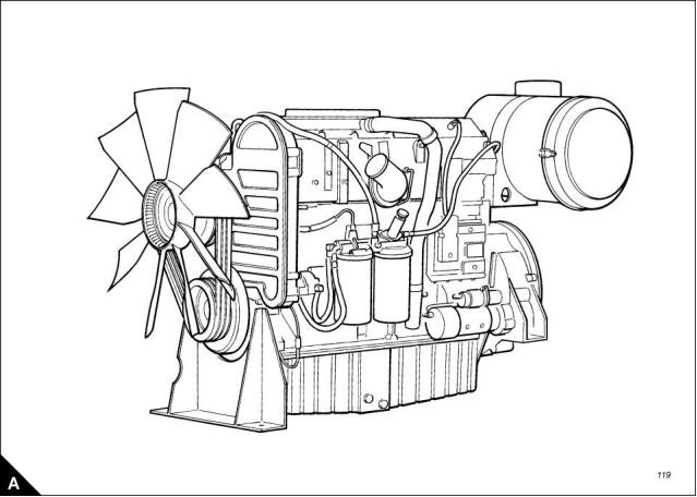
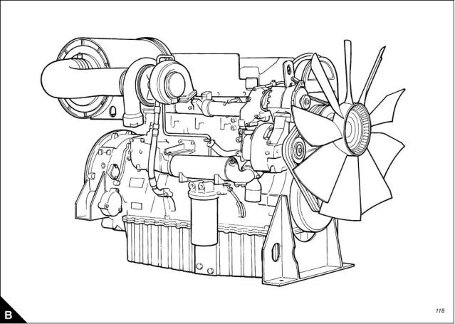
Engine views
Workshop Manual, TSD3455E, Issue 2
5
This document is printed from SPI². Not for RESALE
![]()
![]()
1
2300
Engine identification
If you need parts, service or information for your engine, you must give the complete engine number. The
engine number is stamped on a data plate which is fastened to the right side of the engine.
A typical engine number is: HGA060125U 1103H, which consists of these codes:
H
Code for engine capacity
Engine application
G
A
Engine type
06
0125
U
Number of engine cylinders
Engine specification number
The country of manufacture
Build line number
1103
H
Year of manufacture
Engine lift equipment
A dry engine weighs approximately 1551 kg (3,419 lb). Ensure that the lift equipment used is suitable. An
adjustable lifting beam should be used and the chains or cables must be parallel to each other during use.
Before the engine is lifted:
Always use lift equipment of the approved type and of the correct capacity to lift the engine. Never use a
single lift bracket to raise an engine.
Check the engine lift brackets for damage and security before the engine is lifted.
Use suitable lift equipment or obtain assistance to lift heavy engine components such as the cylinder block,
cylinder head, damper unit, flywheel housing, crankshaft and flywheel.
Warning! The lifting eyes which are fitted to the engine must be used for lifting only the engine. Do NOT use
them to lift the engine if it is still attached to its driven unit.
6
Workshop Manual, TSD3455E, Issue 2
This document is printed from SPI². Not for RESALE
![]()
![]()
![]()
![]()

2300
2
Specifications
2
Basic engine data - 2306 engine
Number of cylinders. ... ... ... ... ... ... ... ... ... ... ... ... ... ... ... ... ... ... ... ... ... ... ... ... ... ... ... ... ... ... ... ... ... ... 6
Cylinder arrangement.. ... ... ... ... ... ... ... ... ... ... ... ... ... ... ... ... ... ... ... ... ... ... ... ... ... ... ... ... ... ... ... .In line
Cycle ... ... ... ... ... ... ... ... ... ... ... ... ... ... ... ... ... ... ... ... ... ... ... ... ... ... ... ... ... ... ... ... ... ... ... ... Four stroke
Induction system.. ... ... ... ... ... ... ... ... ... ... ... ... ... ... ... ... ... ... ... ... ... ... ... ... ... ... ... ... ... ... Turbocharged
Combustion system. ... ... ... ... ... ... ... ... ... ... ... ... ... ... ... ... ... ... ... ... ... ... ... ... ... ... ... ... ...Direct injection
Nominal bore ... ... ... ... ... ... ... ... ... ... ... ... ... ... ... ... ... ... ... ... ... ... ... ... ... ... ... ... ... ... .137 mm (5.394 in)
Nominal stroke. ... ... ... ... ... ... ... ... ... ... ... ... ... ... ... ... ... ... ... ... ... ... ... ... ... ... ... ... ... .165 mm (6.496 in)
Compression ratio ... ... ... ... ... ... ... ... ... ... ... ... ... ... ... ... ... ... ... ... ... ... ... ... ... ... ... ... ... ... ... ... ... 15.9:1
Cubic capacity . ... ... ... ... ... ... ... ... ... ... ... ... ... ... ... ... ... ... ... ... ... ... ... ... ... ... ... ... ... 14,6 litres (893 in3)
Firing order .. ... ... ... ... ... ... ... ... ... ... ... ... ... ... ... ... ... ... ... ... ... ... ... ... ... ... ... ... ... ... ... ... 1, 5, 3, 6, 2, 4
Direction of rotation . ... ... ... ... ... ... ... ... ... ... ... ... ... ... ... ... ... ... ... ... ... Anti-clockwise viewed on flywheel
Lubricating oil capacity:
Total system ... ... ... ... ... ... ... ... ... ... ... ... ... ... ... ... ... ... ... ... ... ... ... ... ... ... ... ... ..68 litres (120 UK pints)
Sump maximum... ... ... ... ... ... ... ... ... ... ... ... ... ... ... ... ... ... ... ... ... ... ... ... ... ... ... ..60 litres (106 UK pints)
Sump minimum ... ... ... ... ... ... ... ... ... ... ... ... ... ... ... ... ... ... ... ... ... ... ... ... ... ... ... ... 45 litres (79 UK pints)
Lubricating oil pressure:
At rated speed . ... ... ... ... ... ... ... ... ... ... ... ... ... ... ... ... ... ... ... ... ... ... ... ... ... ... ... ... ... ... ... ... ... ...4,5 bar
Typical coolant capacity of engine... ... ... ... ... ... ... ... ... ... ... ... ... ... ... ... ... ... ... 20,8 litres (4.6 UK gallons)
Typical coolant capacity of engine and radiator .. ... ... ... ... ... ... ... ... ... ... ... ... ... .47 litres (10.3 UK gallons)
Basic engine data - 2806 engine
Number of cylinders. ... ... ... ... ... ... ... ... ... ... ... ... ... ... ... ... ... ... ... ... ... ... ... ... ... ... ... ... ... ... ... ... ... ... 6
Cylinder arrangement.. ... ... ... ... ... ... ... ... ... ... ... ... ... ... ... ... ... ... ... ... ... ... ... ... ... ... ... ... ... ... ... .In line
Cycle ... ... ... ... ... ... ... ... ... ... ... ... ... ... ... ... ... ... ... ... ... ... ... ... ... ... ... ... ... ... ... ... ... ... ... ... Four stroke
Induction system.. ... ... ... ... ... ... ... ... ... ... ... ... ... ... ... ... ... ... ... ... ... ... ... ... ... ... ... ... ... ... Turbocharged
Combustion system. ... ... ... ... ... ... ... ... ... ... ... ... ... ... ... ... ... ... ... ... ... ... ... ... ... ... ... ... ...Direct injection
Nominal bore ... ... ... ... ... ... ... ... ... ... ... ... ... ... ... ... ... ... ... ... ... ... ... ... ... ... ... ... ... ... .140 mm (5.512 in)
Nominal stroke. ... ... ... ... ... ... ... ... ... ... ... ... ... ... ... ... ... ... ... ... ... ... ... ... ... ... ... ... ... .171 mm (6.732 in)
Compression ratio ... ... ... ... ... ... ... ... ... ... ... ... ... ... ... ... ... ... ... ... ... ... ... ... ... ... ... ... ... ... ... ... ... 15.9:1
Cubic capacity . ... ... ... ... ... ... ... ... ... ... ... ... ... ... ... ... ... ... ... ... ... ... ... ... ... ... ... ...15,8 litres (964.18 in3)
Firing order .. ... ... ... ... ... ... ... ... ... ... ... ... ... ... ... ... ... ... ... ... ... ... ... ... ... ... ... ... ... ... ... ... 1, 5, 3, 6, 2, 4
Direction of rotation . ... ... ... ... ... ... ... ... ... ... ... ... ... ... ... ... ... ... ... ... ... Anti-clockwise viewed on flywheel
Lubricating oil capacity:
Total system ... ... ... ... ... ... ... ... ... ... ... ... ... ... ... ... ... ... ... ... ... ... ... ... ... ... ... ... ..68 litres (120 UK pints)
Sump maximum... ... ... ... ... ... ... ... ... ... ... ... ... ... ... ... ... ... ... ... ... ... ... ... ... ... ... ..60 litres (106 UK pints)
Sump minimum ... ... ... ... ... ... ... ... ... ... ... ... ... ... ... ... ... ... ... ... ... ... ... ... ... ... ... ... 45 litres (79 UK pints)
Lubricating oil pressure:
At rated speed . ... ... ... ... ... ... ... ... ... ... ... ... ... ... ... ... ... ... ... ... ... ... ... ... ... ... ... ... ... ... ... ... ... ...4,5 bar
Typical coolant capacity of engine... ... ... ... ... ... ... ... ... ... ... ... ... ... ... ... ... ... ... 20,8 litres (4.6 UK gallons)
Typical coolant capacity of engine and radiator .. ... ... ... ... ... ... ... ... ... ... ... ... ... ... 50 litres (11 UK gallons)
Workshop Manual, TSD3455E, Issue 2
7
This document is printed from SPI². Not for RESALE
![]()
![]()
2
2300
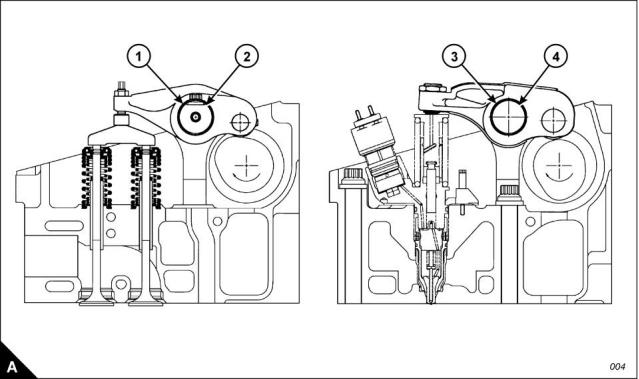
Rocker assemblies
Rocker shaft diameter (A2) ... ... ... ... ... ... ... ... ... ... ... ... ... ... ...40,000 +/- 0,010 mm (1.5748 +/- 0.0004 in)
Valve rocker lever bore (A1) .. ... ... ... ... ... ... ... ... ... ... ... ... ... ...40,065 +/- 0,015 mm (1.5774 +/- 0.0006 in)
Bearing clearance between valve rocker lever and shaft .. ... ... ... ... 0,040 to 0,090 mm (0.0016 to 0.0035 in)
Unit injector rocker lever bore (A3) ... ... ... ... ... ... ... ... ... ... ... ...43,000 +/- 0,020 mm (1.6929 +/- 0.0008 in)
If a new bearing is fitted to the unit injector rocker lever, the oil hole in the bearing must be aligned with the oil
passage in the rocker lever within 2,4 mm (0.09 in). The bearing must not extend beyond either face of the
rocker lever.
Bore in the rocker lever bearing (A4). ... ... ... ... ... ... ... ... ... ... ... .40,065 +/- 0,15 mm (1.5774 +/- 0.0006 in)
Maximum permissible worn dimension.. ... ... ... ... ... ... ... ... ... ... ... ... ... ... ... ... ... ... ... ...40,193 (1.5824 in)
8
Workshop Manual, TSD3455E, Issue 2
This document is printed from SPI². Not for RESALE
![]()
![]()
2
2300
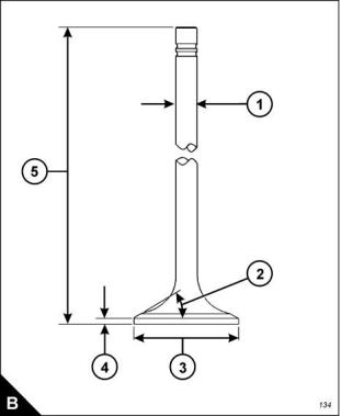
Valves
Diameter of valve stem (B1) ... ... ... ... ... ... ... ... ... ... ... ... ... ... ... 9,441 +/- 0,010 mm (0.3717 +/- 0.0004 in)
Permissible worn dimension ... ... ... ... ... ... ... ... ... ... ... ... ... ... ... ... ... ... ... ... ... ... ... 9,408 mm (0.3704 in)
Diameter of valve head (B3):
Inlet valve ... ... ... ... ... ... ... ... ... ... ... ... ... ... ... ... ... ... ... ... ... ... ... . 47,00 +/- 0,13 mm (1.850 +/- 0.005 in)
Exhaust valve .. ... ... ... ... ... ... ... ... ... ... ... ... ... ... ... ... ... ... ... ... ... . 41,81 +/- 0,13 mm (1.646 +/- 0.005 in)
Angle of face of valve (B2):
Inlet valve ... ... ... ... ... ... ... ... ... ... ... ... ... ... ... ... ... ... ... ... ... ... ... ... ... ... ... ... ... ...29 1/4 +/- 1/4 degrees
Exhaust valve .. ... ... ... ... ... ... ... ... ... ... ... ... ... ... ... ... ... ... ... ... ... ... ... ... ... ... ... ...44 1/4 +/- 1/4 degrees
Minimum thickness of valve lip (B4):
Inlet valve ... ... ... ... ... ... ... ... ... ... ... ... ... ... ... ... ... ... ... ... ... ... ... ... ... ... ... ... ... ... ... 2,75 mm (0.108 in)
Exhaust valve .. ... ... ... ... ... ... ... ... ... ... ... ... ... ... ... ... ... ... ... ... ... ... ... ... ... ... ... ... ... 2,05 mm (0.081 in)
Length of valve:
Inlet.. ... ... ... ... ... ... ... ... ... ... ... ... ... ... ... ... ... ... ... ... ... ... ... ... ... 202,00 +/- 0,45 mm (7.953 +/- 0.018 in)
Exhaust ... ... ... ... ... ... ... ... ... ... ... ... ... ... ... ... ... ... ... ... ... ... ... ... 202,06 +/- 0,45 mm (7.955 +/- 0.018 in)
Workshop Manual, TSD3455E, Issue 2
9
This document is printed from SPI². Not for RESALE
![]()
![]()
2
2300
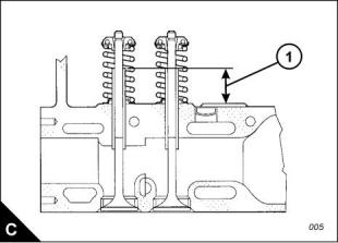
Valve guides
Bore of valve guide when installed ... ... ... ... ... ... ... ... ... ... ... ... ... 9,487 +/- 0,025 mm (0.3735 +/- 0.010 in)
Maximum permissible dimension... ... ... ... ... ... ... ... ... ... ... ... ... ... ... ... ... ... ... ... ... ..9,538 mm (0.3755 in)
Do not use a combination of a valve and valve guide which have a difference of 0,13 mm (0.005 in) or more.
Height from cylinder head to top of valve guide (C1). ... ... ... ... ... ... ... 35,00 +/- 0,50 mm (1.378 +/- 0.020 in)
Valve springs
Inner
Assembled length .. ... ... ... ... ... ... ... ... ... ... ... ... ... ... ... ... ... ... ... ... ... ... ... ... ... ... ... 60,14 mm (2.368 in)
Load at assembled length.. ... ... ... ... ... ... ... ... ... ... ... ... ... ... ... ... ... ... ... ... ... ... ..118 +/- 12 N (27 +/- 3 lb)
Minimum operating length.. ... ... ... ... ... ... ... ... ... ... ... ... ... ... ... ... ... ... ... ... ... ... ... ... 44,02 mm (1.733 in)
Load at minimum operating length. ... ... ... ... ... ... ... ... ... ... ... ... ... ... ... ... ... ... ... ..356 +/- 18 N (80 +/- 4 lb)
Free length after test.. ... ... ... ... ... ... ... ... ... ... ... ... ... ... ... ... ... ... ... ... ... ... ... ... ... ... 71,03 mm (2.797 in)
Outside diameter ... ... ... ... ... ... ... ... ... ... ... ... ... ... ... ... ... ... ... ... ... ... ... ... ... ... ... ... 25,20 mm (0.992 in)
Outer
Assembled length .. ... ... ... ... ... ... ... ... ... ... ... ... ... ... ... ... ... ... ... ... ... ... ... ... ... ... ... 67,12 mm (2.643 in)
Load at assembled length.. ... ... ... ... ... ... ... ... ... ... ... ... ... ... ... ... ... ... ... ... ... ... ..248 +/- 25 N (56 +/- 6 lb)
Minimum operating length.. ... ... ... ... ... ... ... ... ... ... ... ... ... ... ... ... ... ... ... ... ... ... ... ... 51,00 mm (2.008 in)
Load at minimum operating length. ... ... ... ... ... ... ... ... ... ... ... ... ... ... ... ... ... ... ... 756 +/- 35 N (165 +/- 8 lb)
Free length after test.. ... ... ... ... ... ... ... ... ... ... ... ... ... ... ... ... ... ... ... ... ... ... ... ... ... ... 77,88 mm (3.066 in)
Outside diameter ... ... ... ... ... ... ... ... ... ... ... ... ... ... ... ... ... ... ... ... ... ... ... ... ... ... ... ... 36,30 mm (1.429 in)
10
Workshop Manual, TSD3455E, Issue 2
This document is printed from SPI². Not for RESALE
![]()
![]()
2
2300
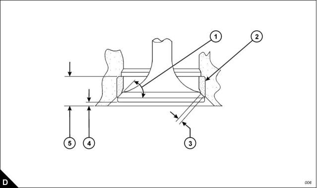
Valve seat inserts
Depth of bore in cylinder head for valve seat insert (D5):
Inlet valve ... ... ... ... ... ... ... ... ... ... ... ... ... ... ... ... ... ... ... ... ... ... ... . 14,00 +/- 0,10 mm (0.551 +/- 0.004 in)
Exhaust valve .. ... ... ... ... ... ... ... ... ... ... ... ... ... ... ... ... ... ... ... ... ... . 13,90 +/- 0,10 mm (0.547 +/- 0.004 in)
Diameter of valve seat insert (D2):
Inlet valve ... ... ... ... ... ... ... ... ... ... ... ... ... ... ... ... ... ... ... ... ... ... 48,025 +/- 0,13 mm (1.8907 +/- 0.0005 in)
Exhaust valve .. ... ... ... ... ... ... ... ... ... ... ... ... ... ... ... ... ... ... ... ... 42,840 +/- 0,13 mm (1.6866 +/- 0.0005 in)
Bore in cylinder head for valve seat insert (D2):
Inlet valve ... ... ... ... ... ... ... ... ... ... ... ... ... ... ... ... ... ... ... ... ... . 47,950 +/- 0,025 mm (1.8878 +/- 0.0010 in)
Exhaust valve .. ... ... ... ... ... ... ... ... ... ... ... ... ... ... ... ... ... ... ... . 42,774 +/- 0,025 mm (1.6840 +/- 0.0010 in)
Angle of face of valve seat insert (D1):
Inlet valve insert... ... ... ... ... ... ... ... ... ... ... ... ... ... ... ... ... ... ... ... ... ... ... ... ... ... ... ...30 1/4 +/- 1/2 degrees
Exhaust valve insert ... ... ... ... ... ... ... ... ... ... ... ... ... ... ... ... ... ... ... ... ... ... ... ... ... ...45 1/4 +/- 1/2 degrees
Valve recess (D4):
Inlet valve (new parts) . ... ... ... ... ... ... ... ... ... ... ... ... ... ... ... ... ... ... ... ..2,20 to 2,80 mm (0.087 to 0.110 in)
Exhaust valve (new parts) ... ... ... ... ... ... ... ... ... ... ... ... ... ... ... ... ... ... ..1,20 to 1,80 mm (0.047 to 0.071 in)
Inlet valve (reconditioned parts) .. ... ... ... ... ... ... ... ... ... ... ... ... ... ... ... ..2,20 to 3,29 mm (0.087 to 0.129 in)
Exhaust valve (reconditioned parts) ... ... ... ... ... ... ... ... ... ... ... ... ... ... ..1,20 to 2,29 mm (0.047 to 0.090 in)
Minimum recommended width of valve seat (D3):
Inlet.. ... ... ... ... ... ... ... ... ... ... ... ... ... ... ... ... ... ... ... ... ... ... ... ... ... ... ... ... ... ... ... ... ... 2,00 mm (0.079 in)
Exhaust ... ... ... ... ... ... ... ... ... ... ... ... ... ... ... ... ... ... ... ... ... ... ... ... ... ... ... ... ... ... ... ... 1,25 mm (0.049 in)
Workshop Manual, TSD3455E, Issue 2
11
This document is printed from SPI². Not for RESALE
![]()
![]()
2
2300
Cylinder head
Thickness of cylinder head (new) .. ... ... ... ... ... ... ... ... ... ... ... ... ... . 120,00 +/- 0,15 mm (4.724 +/- 0.006 in)
Minimum thickness for a used cylinder head. ... ... ... ... ... ... ... ... ... ... ... ... ... ... ... ... ..119,50 mm (4.705 in)
Flatness of cylinder head: The cylinder head must be flat to within a total of 0,13 mm (0.005 in). Additionally,
the cylinder head must be flat within a maximum of 0,03 mm (0.001 in) across any 76,2 mm (3.00 in) spa, n.
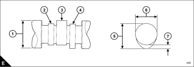
Camshaft and bearings
Diameter of camshaft journal (E3) . ... ... ... ... ... ... ... ... ... ... ... ... ... ... 84,85 +/- 0,02 mm (3.341+/- 0.001 in)
Exhaust lobe lift.. ... ... ... ... ... ... ... ... ... ... ... ... ... ... ... ... ... ... ... ... ... ... ... ... ... ... ... ..8,515 mm (0.3352 in)
Inlet lobe lift ... ... ... ... ... ... ... ... ... ... ... ... ... ... ... ... ... ... ... ... ... ... ... ... ... ... ... ... ... ..9,431 mm (0.3713 in)
Injector lobe lift... ... ... ... ... ... ... ... ... ... ... ... ... ... ... ... ... ... ... ... ... ... ... ... ... ... ... ... 10,451 mm (0.4114 in)
Maximum permissible difference between the actual lobe lift (E7)
and the specified dimension .. ... ... ... ... ... ... ... ... ... ... ... ... ... ... ... ... ... ... ... ... ... ... ... ..1,0 mm (0.0394 in)
To obtain the lobe lift (E7) proceed as follows: Measure the lobe height (E5) and measure the base circle (E6).
Subtract the base circle from the lobe height to give the lobe lift.
12
Workshop Manual, TSD3455E, Issue 2
This document is printed from SPI². Not for RESALE
![]()
![]()
2
2300
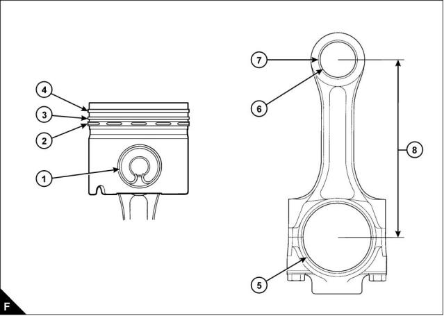
Pistons and connecting rods - 2306 engine
Piston ring gaps measured with the ring fitted in a new liner with a bore size 137.16 mm (5.400 in):
Top piston ring (F4) . ... ... ... ... ... ... ... ... ... ... ... ... ... ... ... ... ... ... ... ... 0,55 +/- 0,15 mm (0.022 +/- 0.006 in)
Intermediate ring (F3) .. ... ... ... ... ... ... ... ... ... ... ... ... ... ... ... ... ... ... ... 0,83 +/- 0,15 mm (0.033 +/- 0.006 in)
Oil control ring (F2).. ... ... ... ... ... ... ... ... ... ... ... ... ... ... ... ... ... ... ... 0,550 +/- 0,15 mm (0.022 +/- 0.0059 in)
Width of groove for oil control ring in new piston. ... ... ... ... ... ... ... ... . 4,03 +/- 0,01 mm (0.159 +/- 0.0004 in)
Thickness of a new oil control ring .. ... ... ... ... ... ... ... ... ... ... ... ... ... 3,98 +/- 0,01 mm (0.1567 +/- 0.0004 in)
Clearance between piston ring groove and new oil control ring.. ... ... . 0,05 +/- 0,02 mm (0.002 +/- 0.0008 in)
Maximum permissible clearance between piston
ring groove and a used oil control ring ... ... ... ... ... ... ... ... ... ... ... ... ... ... ... ... ... ... ... ... 0,15 mm (0.006 in)
Bore of piston crown bearing (F1) ... ... ... ... ... ... ... ... ... ... ... . 55,0355 +/- 0,0055 mm (2.1667 +/- 0.0002 in)
Bore of piston skirt bearing (F1) .. ... ... ... ... ... ... ... ... ... ... ... ... . 55,020 +/- 0,005 mm (2.1661 +/- 0.0002 in)
Gudgeon pin diameter (F1) . ... ... ... ... ... ... ... ... ... ... ... ... ... ... . 55,000 +/- 0,005 mm (2.1654 +/- 0.0002 in)
Length of gudgeon pin. ... ... ... ... ... ... ... ... ... ... ... ... ... ... ... ... ... ... 113,20 +/- 0,15 mm (4.457 +/- 0.006 in)
Bore in connecting rod for small end bearing (F7) .. ... ... ... ... ... . 59,640 +/- 0,013 mm (2.3480 +/- 0.0005 in)
Bore of connecting rod small end bearing (F6) ... ... ... ... ... ... ... . 55,035 +/- 0,008 mm (2.1667 +/- 0.0003 in)
Bore in connecting rod for big end bearing shells (F5) ... ... ... ... . 96,200 +/- 0,013 mm (3.7874 +/- 0.0005 in)
Distance between centres of big and small end bearings (F8) ... ... . 261,62 +/- 0,05 mm (10.300 +/- 0.002 in)
Workshop Manual, TSD3455E, Issue 2
13
This document is printed from SPI². Not for RESALE
![]()
![]()
2
2300
Pistons and connecting rods - 2806 engine
Piston ring gaps measured with the ring fitted in a new liner with a bore size 139,66 mm (5.498 in):
Top piston ring (F4) ... ... ... ... ... ... ... ... ... ... ... ... ... ... ... ... ... ... ... ... .0,50 +/- 0,10 mm (0.020 +/- 0.004 in)
Intermediate ring (F3) ... ... ... ... ... ... ... ... ... ... ... ... ... ... ... ... ... ... ... .0,83 +/- 0,15 mm (0.033 +/- 0.006 in)
Oil control ring (F2) ... ... ... ... ... ... ... ... ... ... ... ... ... ... ... ... ... ... .0,450 +/- 0,150 mm (0.0177 +/- 0.0059 in)
Width of groove for oil control ring in new piston ... ... ... ... ... ... ... .4,033 +/- 0,013 mm (0.1588 +/- 0.0005 in)
Thickness of a new oil control ring. ... ... ... ... ... ... ... ... ... ... ... ... . 3,980 +/- 0,010 mm (0.1567 +/- 0.0004 in)
Clearance between piston ring groove and new oil control ring ... .0,053 +/- 0,023 mm (0.0021 +/- 0.0009 in)
Maximum permissible clearance between piston
ring groove and a used oil control ring... ... ... ... ... ... ... ... ... ... ... ... ... ... ... ... ... ... ... ... ..0,15 mm (0.006 in)
Bore of piston crown bearing (F1).. ... ... ... ... ... ... ... ... ... ... ...55,0355 +/- 0,0055 mm (2.1667 +/- 0.0002 in)
Bore of piston skirt bearing (F1). ... ... ... ... ... ... ... ... ... ... ... ... ...55,020 +/- 0,005 mm (2.1661 +/- 0.0002 in)
Gudgeon pin diameter (F1) ... ... ... ... ... ... ... ... ... ... ... ... ... ... ... 55,000 +/- 0,005 mm (2.1654 +/- 0.0002 in)
Length of gudgeon pin ... ... ... ... ... ... ... ... ... ... ... ... ... ... ... ... ... ... . 113,20 +/- 0,15 mm (4.457 +/- 0.006 in)
Bore in connecting rod for small end bearing (F7). ... ... ... ... ... ... 59,640 +/- 0,013 mm (2.3480 +/- 0.0005 in)
Bore of connecting rod small end bearing (F6).. ... ... ... ... ... ... ... 55,035 +/- 0,008 mm (2.1667 +/- 0.0003 in)
Bore in connecting rod for big end bearing shells (F5) .. ... ... ... ...96,200 +/- 0,013 mm (3.7874 +/- 0.0005 in)
Distance between centres of big and small end bearings (F8).. ... ...261,62 +/- 0,05 mm (10.300 +/- 0.002 in)
14
Workshop Manual, TSD3455E, Issue 2
This document is printed from SPI². Not for RESALE
![]()
![]()

2
2300
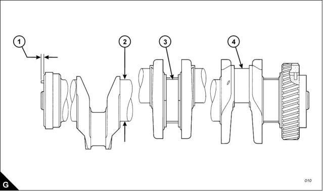
Crankshaft, main bearings and flywheel
Diameter of main bearing journal (G2) ... ... ... ... ... ... ... ... ... ... 120,650 +/- 0,020 mm (4.7500 +/- 0.0008 in)
Journal undersize by 0,63 mm (0.025 in) ... ... ... ... ... ... ... ... ... ... .. 120,015 +/- 0,020 (4.7250 +/- 0.0008 in)
Journal undersize by 1,27 mm (0.050 in) ... ... ... ... ... ... ... ... ... 119,380 +/- 0,020 mm (4.7000 +/- 0.0008 in)
Clearance between a new bearing and the journal (G3). ... ... ... ... ..0,091 to 0,186 mm (0.0036 to 0.0073 in)
Maximum permissible clearance between the
bearing and journal.. ... ... ... ... ... ... ... ... ... ... ... ... ... ... ... ... ... ... ... ... ... ... ... ... ... ... ... 0,25 mm (0.010 in)
Diameter of main bearing bore ... ... ... ... ... ... ... ... ... ... ... ... ... 129,891 +/- 0,013 mm (5.1138 +/- 0.0005 in)
Diameter of main bearing bore, oversize by 0,63 mm (0.025 in). 130,526 +/- 0,013 mm (5.1388 +/- 0.0005 in)
Diameter of connecting rod journal (G4) . ... ... ... ... ... ... ... ... ... . 90,000 +/- 0,020 mm (3.5433 +/- 0.0008 in)
Journal undersize by 0,63 mm (0.025 in) ... ... ... ... ... ... ... ... ... ... ... 89,370 +/- 0,020 (3.5185 +/- 0.0008 in)
Journal undersize by 1,27 mm (0.050 in) ... ... ... ... ... ... ... ... ... . 88,730 +/- 0,020 mm (3.4933 +/- 0.0008 in)
Clearance between a new bearing and the journal . ... ... ... ... ... ... ..0,062 to 0,160 mm (0.0024 to 0.0063 in)
Maximum permissible clearance between the
bearing and journal.. ... ... ... ... ... ... ... ... ... ... ... ... ... ... ... ... ... ... ... ... ... ... ... ... ... ... ... 0,20 mm (0.008 in)
End-float of crankshaft. ... ... ... ... ... ... ... ... ... ... ... ... ... ... ... ... ... ... ... .. 0,15 to 0,55 mm (0.006 to 0.022 in)
Maximum permissible end-float (with used bearings) . ... ... ... ... ... ... ... ... ... ... ... ... ... ... 0,89 mm (0.035 in)
Maximum protrusion of dowel (G1) . ... ... ... ... ... ... ... ... ... ... ... ... ... ... ... ... ... ... ... ... ... ... 6,4 mm (0.25 in)
Crankshaft damper
Maximum permissible run-out of face of damper ... ... ... ... ... ... ... ... ... ... ... ... ... ... ... ... 2,03 mm (0.080 in)
Workshop Manual, TSD3455E, Issue 2
15
This document is printed from SPI². Not for RESALE
![]()
![]()
2
2300
Crankcase and cylinder liners
Thickness of spacer plate (H3) .. ... ... ... ... ... ... ... ... ... ... ... ... ... .8,585 +/- 0,025 mm (0.3380 +/- 0.0010 in)
Thickness of gasket fitted between spacer plate and crankcase... . 0,238 +/- 0,032 mm (0.0094 +/- 0.0013 in)
Cylinder liner protrusion (H5) above the spacer plate ... ... ... ... ... ... 0,025 to 0,152 mm (0.0010 to 0.0060 in)
Maximum variation in each cylinder liner... ... ... ... ... ... ... ... ... ... ... ... ... ... ... ... ... ... ..0,051 mm (0.0020 in)
Maximum average variation between adjacent cylinder liners... ... ... ... ... ... ... ... ... ... ..0,051 mm (0.0020 in)
Maximum variation between all cylinder liners... ... ... ... ... ... ... ... ... ... ... ... ... ... ... ... ..0,102 mm (0.0040 in)
Refer to Operation 7-3 for further cylinder liner information.
Protrusion of front cylinder head dowel (H6) above top face of crankcase ...16,0 +/- 0,5 mm (0.63 +/- 0.02 in)
Protrusion of rear cylinder head dowel (H4) above top face of crankcase ...18,5 +/- 0,5 mm (0.73 +/- 0.02 in)
Protrusion of oil transfer tube (H7) above top face of crankcase... ... ... ... ... 20,0 +/- 0,5 mm (0.79 +/- 0.02 in)
Protrusion of flywheel housing dowels (H1) from rear face of crankcase.. ...19,1 +/- 0,5 mm (0.75 +/- 0.02 in)
Protrusion of gear case dowels (H8) from front face of crankcase ... ... ... ...19,1 +/- 0,5 mm (0.75 +/- 0.02 in)
Plug (H2) must be tightened to a torque of ... ... ... ... ... ... ... ... ... ... ... ... ... ... ... 70 +/- 10 Nm (52 +/- 7 lbf ft)
The total flatness of the top face of the crankcase must be within 0,10 mm (0.004 in). The flatness must also
be within 0,05 mm (0.002 in) for any 177,5 mm (6.99 in) section of the surface.
Continued
16
Workshop Manual, TSD3455E, Issue 2
This document is printed from SPI². Not for RESALE
![]()
![]()

2
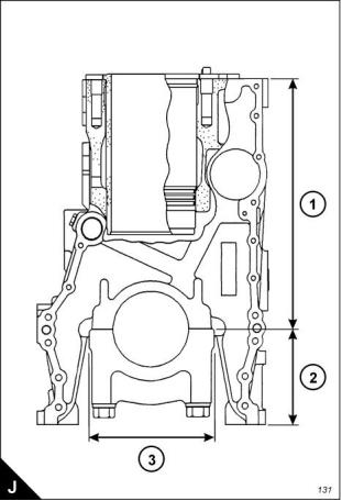
2300
Distance from top of crankcase to centre of main
bearing bore (J1) . ... ... ... ... ... ... ... ... ... ... ... ... ... ... ... ... ... ... ... . 425,45 +/- 0,15 mm (16.750 +/- 0.006 in)
Minimum permissible (J1) ... ... ... ... ... ... ... ... ... ... ... ... ... ... ... ... ... ... ... ... ... ... ... ..425,02 mm (16.733 in)
Distance from bottom of crankcase to centre of main
bearing bore (J2) . ... ... ... ... ... ... ... ... ... ... ... ... ... ... ... ... ... ... ... ... 165,10 +/- 0,10 mm (6.500 +/- 0.004 in)
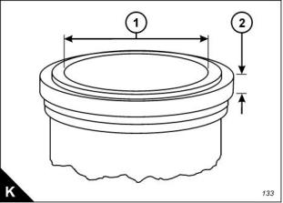
Bore in new cylinder liner - 2306 engine (K1).. ... ... ... ... ... ... ... 137,185 +/- 0,025 mm (5.4010 +/- 0.0010 in)
Bore in new cylinder liner - 2806 engine (K1).. ... ... ... ... ... ... ... 139,685 +/- 0,025 mm (5.4994 +/- 0.0010 in)
Thickness of liner flange (K2).. ... ... ... ... ... ... ... ... ... ... ... ... ... ... 8,890 +/- 0,020 mm (0.3500 +/- 0.0008 in)
Minimum thickness permissible (K2) ... ... ... ... ... ... ... ... ... ... ... ... ... ... ... ... ... ... ... ... 8,870 mm (0.3492 in)
Workshop Manual, TSD3455E, Issue 2
17
This document is printed from SPI². Not for RESALE
![]()
![]()
2
2300
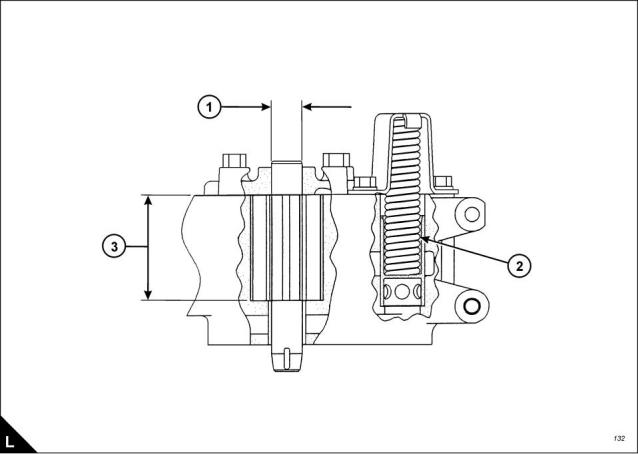
Lubricating oil pump
Diameter of shafts (L1) .. ... ... ... ... ... ... ... ... ... ... ... ... ... ... ... ...22,217 +/- 0,005 mm (0.8747 +/- 0.0002 in)
Diameter of bores in cover for shafts. ... ... ... ... ... ... ... ... ... ... ...22,258 +/- 0,008 mm (0.8763 +/- 0.0003 in)
Length of gears (L3)... ... ... ... ... ... ... ... ... ... ... ... ... ... ... ... ... ...79,375 +/- 0,025 mm (3.1250 +/- 0.0010 in)
Depth of bores for gears (L3). ... ... ... ... ... ... ... ... ... ... ... ... ... ... 79,502 +/- 0,020 mm (3.1300 +/- 0.0008 in)
Spring (L2):
Test force... ... ... ... ... ... ... ... ... ... ... ... ... ... ... ... ... ... ... ... ... ... ... ... ... ... ... . 150 +/- 8 Nm (110 +/- 6 lbf ft)
Length under test force.. ... ... ... ... ... ... ... ... ... ... ... ... ... ... ... ... ... ... ... ... ... ... ... ... ... ..117,9 mm (4.64 in)
Free length after test.. ... ... ... ... ... ... ... ... ... ... ... ... ... ... ... ... ... ... ... ... ... ... ... ... ... ... ..152,9 mm (6.02 in)
Outside diameter ... ... ... ... ... ... ... ... ... ... ... ... ... ... ... ... ... ... ... ... ... ... ... ... ... ... ... ... ... .27 mm (1.063 in)
18
Workshop Manual, TSD3455E, Issue 2
This document is printed from SPI². Not for RESALE
![]()
![]()
2
2300
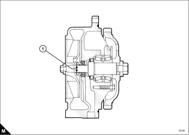
Coolant pump
Shaft diameter at the position of the coolant seal (M1) ... ... ... ... ... . 19,10 +/- 0,01 mm (0.7520 +/- 0.0004 in)
Workshop Manual, TSD3455E, Issue 2
19
This document is printed from SPI². Not for RESALE
![]()
![]()
2
2300
Recommended torque figures
Exceptions to these torque figures are given in the Workshop Manual where necessary.
Before any components are fitted to the engine, ensure that they are in a new or close to new condition. Bolts
or threads must not be worn or damaged. Components must be free from rust or other corrosion. Clean with
a non-corrosive cleaner if necessary. Do not lubricate the threads of fasteners. Rust preventative which has
been applied by the component supplier for shipping and storage is acceptable. Certain components may
require an application of a particular lubricant, details are given in the Workshop Manual where relevant.
Standard torque figures for metric fasteners
Metric nuts and bolts
Thread size
Standard torque
metric
M6
12 +/- 3 Nm (9 +/- 2 lbf ft)
28 +/- 7 Nm (21 +/- 5 lbf ft)
M8
M10
M12
M14
M16
M20
M24
M30
M36
55 +/- 10 Nm (41 +/- 7 lbf ft)
100 +/- 20 Nm (75 +/- 15 lbf ft)
160 +/- 30 Nm (120 +/- 22 lbf ft)
240 +/- 40 Nm (175 +/- 30 lbf ft)
460 +/- 60 Nm (340 +/- 44 lbf ft)
800 +/- 100 Nm (590 +/- 75 lbf ft)
1600 +/- 200 Nm (1180 +/- 150 lbf ft)
2700 +/- 300 Nm (2000 +/- 220 lbf ft)
Metric taperlock studs
Thread size
metric
Standard torque
M6
8 +/- 3 Nm (6 +/- 2 lbf ft)
17 +/- 5 Nm (13 +/- 4 lbf ft)
M8
M10
M12
M16
M20
M24
M30
M36
35 +/- 5 Nm (26 +/- 4 lbf ft)
65 +/- 10 Nm (48 +/- 7 lbf ft)
110 +/- 20 Nm (80 +/- 15 lbf ft)
170 +/- 30 Nm (125 +/- 22 lbf ft)
400 +/- 60 Nm (300 +/- 44 lbf ft)
750 +/- 80 Nm (550 +/- 60 lbf ft)
1200 +/- 150 Nm (880 +/- 110 lbf ft)
20
Workshop Manual, TSD3455E, Issue 2
This document is printed from SPI². Not for RESALE
![]()
![]()


2
2300
Standard torque figures for imperial fasteners
Imperial nuts and bolts
Thread size
inches
Standard torque
1/4
5/16
3/8
12 +/- 3 Nm (9 +/- 2 lbf ft)
25 +/- 6 Nm (18 +/- 4 lbf ft)
47 +/- 9 Nm (35 +/- 7 lbf ft)
7/16
1/2
70 +/- 15 Nm (50 +/- 11 lbf ft)
105 +/- 20 Nm (75 +/- 15 lbf ft)
160 +/- 30 Nm (120 +/- 22 lbf ft)
215 +/- 40 Nm (160 +/- 30 lbf ft)
370 +/- 50 Nm (275 +/- 37 lbf ft)
620 +/- 80 Nm (460 +/- 60 lbf ft)
900 +/- 100 Nm (660 +/- 75 lbf ft)
1300 +/- 150 Nm (960 +/- 110 lbf ft)
1800 +/- 200 Nm (1320 +/- 150 lbf ft)
2400 +/- 300 Nm (1780 +/- 220 lbf ft)
3100 +/- 350 Nm (2280 +/- 260 lbf ft)
9/16
5/8
3/4
7/8
1
1 1/8
1 1/4
1 3/8
1 1/2
Imperial taperlock studs
Thread size
inches
Standard torque
1/4
5/16
3/8
8 +/- 3 Nm (6 +/- 2 lbf ft)
17 +/- 5 Nm (13 +/- 4 lbf ft)
35 +/- 5 Nm (26 +/- 4 lbf ft)
7/16
1/2
45 +/- 10 Nm (33 +/- 7 lbf ft)
65 +/- 10 Nm (48 +/- 7 lbf ft)
110 +/- 20 Nm (80 +/- 15 lbf ft)
170 +/- 30 Nm (125 +/- 22 lbf ft)
260 +/- 40 Nm (190 +/- 30 lbf ft)
400 +/- 60 Nm (300 +/- 44 lbf ft)
525 +/- 60 Nm (390 +/- 44 lbf ft)
750 +/- 80 Nm (550 +/- 60 lbf ft)
950 +/- 125 Nm (700 +/- 90 lbf ft)
1200 +/- 150 Nm (880 +/- 110 lbf ft)
5/8
3/4
7/8
1
1 1/8
1 1/4
1 3/8
1 1/2
Workshop Manual, TSD3455E, Issue 2
21
This document is printed from SPI². Not for RESALE
![]()
![]()


2
2300
Standard torque figures for ‘O’ ring face seal fittings and 37 degree flared fittings
Torque figures for ferrous straight thread ‘O’ ring fittings when connected to ferrous materials
Thread size
Inches
Standard
torque
Outside diameter of nominal tube
3,18 mm
(0.125 in)
5,0 +/- 1,5 Nm
(4 +/- 1 lbf ft)
5/16 - 24
3/8 - 24
4,76 mm
(0.188 in)
12 +/- 2 Nm
(9 +/- 1 lbf ft)
6,35 mm
(0.250 in)
22 +/- 2 Nm
(16 +/- 1 lbf ft)
7/16 - 20
1/2 - 20
7,94 mm
(0.312 in)
30 +/- 3 Nm
(22 +/- 2 lbf ft)
9,52 mm
(0.375 in)
48 +/- 5 Nm
(35 +/- 4 lbf ft)
9/16 - 18
3/4 - 16
12,70 mm
(0.500 in)
82 +/- 8 Nm
(60 +/- 6 lbf ft)
15,88 mm
(0.625 in)
143 +/- 15 Nm
(105 +/- 11 lbf ft)
7/8 - 14
19,05 mm
(0.750 in)
190 +/- 20 Nm
(140 +/- 15 lbf ft)
1 1/16 - 12
1 3/16 - 12
1 5/16 - 12
1 5/8 - 12
1 7/8 - 12
2 1/2 - 12
22,22 mm
(0.875 in)
250 +/- 25 Nm
(185 +/- 18 lbf ft)
25,40 mm
(1.000 in)
300 +/- 30 Nm
(220 +/- 22 lbf ft)
31,75 mm
(1.250 in)
350 +/- 30 Nm
(260 +/- 22 lbf ft)
38,10 mm
(1.500 in)
430 +/- 40 Nm
(320 +/- 30 lbf ft)
50,80 mm
(2.000 in)
450 +/- 45 Nm
(330 +/- 33 lbf ft)
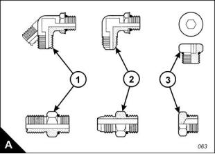
Note: For the table above, use 50 percent of the torque figure when the fitting, the plug or the port material is
nonferrous.
Examples of relevant fittings are shown (A): ‘O’ ring face seal (A1), 37 degree flare (A2) and plug with a
hexagon or socket-type head (A3).
22
Workshop Manual, TSD3455E, Issue 2
This document is printed from SPI². Not for RESALE
![]()
![]()

免费热线
400-100-8969 15088860848
400-100-8969 15088860848
机组销售
0574-26871589 15267810868
0574-26871589 15267810868
配件销售
0574-26886646 15706865167
0574-26886646 15706865167
维修热线
0574-26871569 18658287286
0574-26871569 18658287286
手机端

微信公众号