 English
 Espaol
 Franais
 阿拉伯
阿拉伯 中文(简)
中文(简) Deutsch
 Italiano
 Português
 日本
日本 韩国
韩国 български
 hrvatski
 esky
esky Dansk
Dansk Nederlands
 suomi
suomi Ελληνικ
 印度
印度 norsk
norsk Polski
 Roman
Roman русский
 Svenska
 Perkins2306A(C)-E14发动机故障维修诊断手册,Perkins2306A(C)-E14发动机故障维修诊断手册技术支持中心,Perkins2306A(C)-E14发动机故障维修诊断手册代理商,Perkins2306A(C)-E14发动机故障维修诊断手册销售服务中心,Perkins2306A(C)-E14发动机故障维修诊断手册价格规格资料查询,宁波日昕动力科技有限公司

Perkins2306A(C)-E14发动机故障维修诊断手册
详细描述
Perkins 2300 Series
Models 2306A-E14 and 2306C-E14
DIAGNOSTIC MANUAL
6 cylinder turbocharged diesel engine
Publication TSD 3457E, Issue 2.
© Proprietary information of Perkins Engines Company Limited, all rights reserved.
The information is correct at the time of print.
Published in December 2006 by Technical Publications,
Perkins Engines Company Limited, Peterborough PE1 5NA England.
Diagnostic Manual, TSD 3457E, Issue 2
i
This document is printed from SPI². Not for RESALE
![]()
![]()
Chapters
1 General information
2 Electronic system overview
3 Programming parameters
4 Fault diagnosis
5 Special Tools
The following pages contain a detailed table of contents
ii
Diagnostic Manual, TSD 3457E, Issue 2
This document is printed from SPI². Not for RESALE
![]()
![]()
![]()
2300 Series
Contents
1 General information
Introduction ... ... ... ... ... ... ... ... ... ... ... ... ... ... ... ... ... ... ... ... ... ... ... ... ... ... ... ... ... ...1
Safety precautions ... ... ... ... ... ... ... ... ... ... ... ... ... ... ... ... ... ... ... ... ... ... ... ... ... ... ... 2
Glossary of terms . ... ... ... ... ... ... ... ... ... ... ... ... ... ... ... ... ... ... ... ... ... ... ... ... ... ... ...3
2 Electronic system overview
System operation .. ... ... ... ... ... ... ... ... ... ... ... ... ... ... ... ... ... ... ... ... ... ... ... ... ... ... ...9
Electronic controls ... ... ... ... ... ... ... ... ... ... ... ... ... ... ... ... ... ... ... ... ... ... ... ... ... ... ... 9
Engine governor ... ... ... ... ... ... ... ... ... ... ... ... ... ... ... ... ... ... ... ... ... ... ... ... ... ... ... ...9
Timing considerations .. ... ... ... ... ... ... ... ... ... ... ... ... ... ... ... ... ... ... ... ... ... ... ... ... ...9
Fuel injection . ... ... ... ... ... ... ... ... ... ... ... ... ... ... ... ... ... ... ... ... ... ... ... ... ... ... ... ... .10
Engine monitoring ... ... ... ... ... ... ... ... ... ... ... ... ... ... ... ... ... ... ... ... ... ... ... ... ... ... .11
Fuel temperature monitoring ... ... ... ... ... ... ... ... ... ... ... ... ... ... ... ... ... ... ... ... ... ... .11
Self diagnostics ... ... ... ... ... ... ... ... ... ... ... ... ... ... ... ... ... ... ... ... ... ... ... ... ... ... ... .11
Effect of diagnostic codes on engine performance .. ... ... ... ... ... ... ... ... ... ... ... ... .12
Current totals stored in the ECM . ... ... ... ... ... ... ... ... ... ... ... ... ... ... ... ... ... ... ... ... .12
Programmable parameters .. ... ... ... ... ... ... ... ... ... ... ... ... ... ... ... ... ... ... ... ... ... ... .12
Passwords . ... ... ... ... ... ... ... ... ... ... ... ... ... ... ... ... ... ... ... ... ... ... ... ... ... ... ... ... ... .13
Diagnostic Manual, TSD 3457E, Issue 2
iii
This document is printed from SPI². Not for RESALE
![]()
![]()
![]()
2300 Series
Engine component diagram . ... ... ... ... ... ... ... ... ... ... ... ... ... ... ... ... ... ... ... ... ... ... 14
OEM connection diagram . ... ... ... ... ... ... ... ... ... ... ... ... ... ... ... ... ... ... ... ... ... ... ... 15
Sensor and connector location diagram . ... ... ... ... ... ... ... ... ... ... ... ... ... ... ... ... ... 16
Engine wiring diagram .. ... ... ... ... ... ... ... ... ... ... ... ... ... ... ... ... ... ... ... ... ... ... ... ... 17
Machine wiring diagram (all options) .. ... ... ... ... ... ... ... ... ... ... ... ... ... ... ... ... ... ... 18
Electrical connectors and functions ... ... ... ... ... ... ... ... ... ... ... ... ... ... ... ... ... ... ... 19
Colour codes .. ... ... ... ... ... ... ... ... ... ... ... ... ... ... ... ... ... ... ... ... ... ... ... ... ... ... ... ... 19
Service tools and diagnostics .. ... ... ... ... ... ... ... ... ... ... ... ... ... ... ... ... ... ... ... ... ... 20
3 Programming parameters
Connecting the TIPSS-EST ... ... ... ... ... ... ... ... ... ... ... ... ... ... ... ... ... ... ... ... ... ... ... 21
Passwords .. ... ... ... ... ... ... ... ... ... ... ... ... ... ... ... ... ... ... ... ... ... ... ... ... ... ... ... ... ... 23
Programming a new ECM . ... ... ... ... ... ... ... ... ... ... ... ... ... ... ... ... ... ... ... ... ... ... ... 24
Programming an ECM using flash programming ... ... ... ... ... ... ... ... ... ... ... ... ... ... 27
ECM date/time clock .. ... ... ... ... ... ... ... ... ... ... ... ... ... ... ... ... ... ... ... ... ... ... ... ... ... 28
ECM diagnostic clock ... ... ... ... ... ... ... ... ... ... ... ... ... ... ... ... ... ... ... ... ... ... ... ... ... 29
Injector codes ... ... ... ... ... ... ... ... ... ... ... ... ... ... ... ... ... ... ... ... ... ... ... ... ... ... ... ... 29
TIPSS-EST cylinder cut-out test ... ... ... ... ... ... ... ... ... ... ... ... ... ... ... ... ... ... ... ... ... 29
Programming parameters . ... ... ... ... ... ... ... ... ... ... ... ... ... ... ... ... ... ... ... ... ... ... ... 29
System configuration parameters ... ... ... ... ... ... ... ... ... ... ... ... ... ... ... ... ... ... ... ... 30
Customer specified parameters ... ... ... ... ... ... ... ... ... ... ... ... ... ... ... ... ... ... ... ... ... 32
4 Fault diagnosis
Introduction ... ... ... ... ... ... ... ... ... ... ... ... ... ... ... ... ... ... ... ... ... ... ... ... ... ... ... ... ... 35
Diagnostic procedures without a diagnostic fault code
General information .. ... ... ... ... ... ... ... ... ... ... ... ... ... ... ... ... ... ... ... ... ... ... ... ... ... 36
iv
Diagnostic Manual, TSD 3457E, Issue 2
This document is printed from SPI². Not for RESALE
![]()
![]()
![]()
2300 Series
Diagnostic symptoms
Test 1 - Engine will not crank ... ... ... ... ... ... ... ... ... ... ... ... ... ... ... ... ... ... ... ... ... ... .37
Test 2 - Engine cranks but will not start ... ... ... ... ... ... ... ... ... ... ... ... ... ... ... ... ... ... .38
Test 3 - Engine misfires, runs rough or is unstable ... ... ... ... ... ... ... ... ... ... ... ... ... ... .39
Test 4 - Low power/poor or no response to throttle ... ... ... ... ... ... ... ... ... ... ... ... ... ... .40
Test 5 - Intermittent engine shutdowns . ... ... ... ... ... ... ... ... ... ... ... ... ... ... ... ... ... ... .41
Test 6 - Intermittent low power or power cut-outs . ... ... ... ... ... ... ... ... ... ... ... ... ... ... .42
Test 7 - Electronic service tool will not communicate with the ECM . ... ... ... ... ... ... ... .43
Test 8 - ECM will not accept factory passwords ... ... ... ... ... ... ... ... ... ... ... ... ... ... ... .44
Test 9 - Excessive black smoke ... ... ... ... ... ... ... ... ... ... ... ... ... ... ... ... ... ... ... ... ... .45
Test 10 - Excessive white smoke .. ... ... ... ... ... ... ... ... ... ... ... ... ... ... ... ... ... ... ... ... .46
Test 11 - Excessive blue smoke ... ... ... ... ... ... ... ... ... ... ... ... ... ... ... ... ... ... ... ... ... .47
Test 12 - Engine cannot reach correct rev/min . ... ... ... ... ... ... ... ... ... ... ... ... ... ... ... .48
Test 13 - Poor acceleration or response ... ... ... ... ... ... ... ... ... ... ... ... ... ... ... ... ... ... .49
Test 14 - Poor fuel consumption ... ... ... ... ... ... ... ... ... ... ... ... ... ... ... ... ... ... ... ... ... .50
Test 15 - Too much vibration . ... ... ... ... ... ... ... ... ... ... ... ... ... ... ... ... ... ... ... ... ... ... .51
Test 16 - Noise coming from cylinder ... ... ... ... ... ... ... ... ... ... ... ... ... ... ... ... ... ... ... .52
Test 17 - Excessive valve clearance . ... ... ... ... ... ... ... ... ... ... ... ... ... ... ... ... ... ... ... .53
Test 18 - Valve rotocoil or spring lock is free ... ... ... ... ... ... ... ... ... ... ... ... ... ... ... ... .54
Test 19 - Mechanical noise (knock) in engine ... ... ... ... ... ... ... ... ... ... ... ... ... ... ... ... .55
Test 20 - Oil in cooling system .. ... ... ... ... ... ... ... ... ... ... ... ... ... ... ... ... ... ... ... ... ... .56
Test 21 - Fuel in cooling system ... ... ... ... ... ... ... ... ... ... ... ... ... ... ... ... ... ... ... ... ... .57
Test 22 - Coolant in lubricating oil . ... ... ... ... ... ... ... ... ... ... ... ... ... ... ... ... ... ... ... ... .58
Test 23 - Fuel dilution of lubricating oil .. ... ... ... ... ... ... ... ... ... ... ... ... ... ... ... ... ... ... .59
Test 24 - Engine has early wear ... ... ... ... ... ... ... ... ... ... ... ... ... ... ... ... ... ... ... ... ... .60
Test 25 - Engine has low oil pressure ... ... ... ... ... ... ... ... ... ... ... ... ... ... ... ... ... ... ... .61
Test 26 - Engine uses too much lubricating oil .. ... ... ... ... ... ... ... ... ... ... ... ... ... ... ... .62
Test 27 - Engine coolant is too hot ... ... ... ... ... ... ... ... ... ... ... ... ... ... ... ... ... ... ... ... .63
Test 28 - Oil at the exhaust ... ... ... ... ... ... ... ... ... ... ... ... ... ... ... ... ... ... ... ... ... ... ... .64
Test 29 - Engine has a fuel supply problem .. ... ... ... ... ... ... ... ... ... ... ... ... ... ... ... ... .65
Test 30 - Indicator lamp not functioning correctly .. ... ... ... ... ... ... ... ... ... ... ... ... ... ... .66
Test 31 - Inlet air manifold temperature is too high ... ... ... ... ... ... ... ... ... ... ... ... ... ... .67
Test 32 - Engine has a high fuel temperature ... ... ... ... ... ... ... ... ... ... ... ... ... ... ... ... .68
Diagnostic procedures with an event code
General information .. ... ... ... ... ... ... ... ... ... ... ... ... ... ... ... ... ... ... ... ... ... ... ... ... ... .69
Event codes ... ... ... ... ... ... ... ... ... ... ... ... ... ... ... ... ... ... ... ... ... ... ... ... ... ... ... ... ... .69
Diagnostic tests
Test 33 - High intake manifold pressure ... ... ... ... ... ... ... ... ... ... ... ... ... ... ... ... ... ... .70
Test 34 - Low oil pressure . ... ... ... ... ... ... ... ... ... ... ... ... ... ... ... ... ... ... ... ... ... ... ... .71
Test 35 - High coolant temperature ... ... ... ... ... ... ... ... ... ... ... ... ... ... ... ... ... ... ... ... .72
Test 36 - Engine overspeed .. ... ... ... ... ... ... ... ... ... ... ... ... ... ... ... ... ... ... ... ... ... ... .73
Test 37 - High fuel temperature . ... ... ... ... ... ... ... ... ... ... ... ... ... ... ... ... ... ... ... ... ... .74
Test 38 - High intake manifold air temperature . ... ... ... ... ... ... ... ... ... ... ... ... ... ... ... .75
Diagnostic Manual, TSD 3457E, Issue 2
v
This document is printed from SPI². Not for RESALE
![]()
![]()
![]()
2300 Series
Diagnostic procedures with a diagnostic fault code
General information .. ... ... ... ... ... ... ... ... ... ... ... ... ... ... ... ... ... ... ... ... ... ... ... ... ... 76
Diagnostic codes ... ... ... ... ... ... ... ... ... ... ... ... ... ... ... ... ... ... ... ... ... ... ... ... ... ... ... 76
Diagnostic terminology . ... ... ... ... ... ... ... ... ... ... ... ... ... ... ... ... ... ... ... ... ... ... ... ... 78
Connectors . ... ... ... ... ... ... ... ... ... ... ... ... ... ... ... ... ... ... ... ... ... ... ... ... ... ... ... ... ... 79
Diagnostic tests
Test 39 - Inspecting electrical connectors .. ... ... ... ... ... ... ... ... ... ... ... ... ... ... ... ... ... 82
Test 40 - Electrical power supply to the ECM ... ... ... ... ... ... ... ... ... ... ... ... ... ... ... ... 88
Test 41 - Analogue sensor open or short circuit test . ... ... ... ... ... ... ... ... ... ... ... ... ... 91
Test 42 - ECM Status indicator output circuit test .. ... ... ... ... ... ... ... ... ... ... ... ... ... .. 101
Test 43 - +5 V Sensor voltage supply circuit test ... ... ... ... ... ... ... ... ... ... ... ... ... ... .. 107
Test 44 - PWM desired speed setting circuit test ... ... ... ... ... ... ... ... ... ... ... ... ... ... .. 112
Test 45 - Perkins Data Link circuit test .. ... ... ... ... ... ... ... ... ... ... ... ... ... ... ... ... ... .. 118
Test 46 - Engine speed/timing circuit test .. ... ... ... ... ... ... ... ... ... ... ... ... ... ... ... ... .. 126
Test 47 - Engine speed/timing calibration .. ... ... ... ... ... ... ... ... ... ... ... ... ... ... ... ... .. 134
Test 48 - Injector solenoids circuit test ... ... ... ... ... ... ... ... ... ... ... ... ... ... ... ... ... ... .. 138
Test 49 - Analogue sensor abnormal test .. ... ... ... ... ... ... ... ... ... ... ... ... ... ... ... ... .. 146
5 Special tools
Required service tools .. ... ... ... ... ... ... ... ... ... ... ... ... ... ... ... ... ... ... ... ... ... ... ... .. 149
Optional service tools ... ... ... ... ... ... ... ... ... ... ... ... ... ... ... ... ... ... ... ... ... ... ... ... .. 150
vi
Diagnostic Manual, TSD 3457E, Issue 2
This document is printed from SPI². Not for RESALE
![]()
![]()
![]()
2300 Series
1
General information
1
Introduction
The 2300 and 2800 Series industrial diesel engines are the latest development from Perkins Engines
Company Limited, a world leader in the design and manufacture of high performance diesel engines.
Read and remember the "Safety precautions" on page 2. They are given for your protection and must be
applied at all times.
Danger is indicated in the text by two methods:
Warning! This indicates that there is a possible danger to the person.
Caution: This indicates that there is a possible danger to the engine.
Note: Is used where the information is important, but there is not a danger.
Ensure that all adjustments and repairs are done by personnel who have had the correct training.
Diagnostic Manual, TSD 3457E, Issue 2
1
This document is printed from SPI². Not for RESALE
![]()
![]()
![]()
1
2300 Series
Safety precautions
These safety precautions are important. Reference must also be made to the local regulations in the country
of operation.
Only use these engines in the type of application for which they have been designed.
Do not change the specification of the engine.
Do not smoke when you put fuel in the tank.
Clean away fuel which has been spilt. Material which has been contaminated by fuel must be moved to a
safe place.
Do not put fuel in the tank while the engine runs (unless it is absolutely necessary).
Do not clean, add lubricating oil, or adjust the engine while it runs (unless you have had the correct training;
even then extreme caution must be used to prevent injury).
Do not make adjustments that you do not understand.
Ensure that the engine does not run in a location where it can cause a concentration of toxic emissions.
Other persons must be kept at a safe distance while the engine or equipment is in operation.
Do not permit loose clothing or long hair near moving parts.
Keep away from moving parts during engine operation.
Warning! Some moving parts cannot be seen clearly while the engine runs.
Do not operate the engine if a safety guard has been removed.
Do not remove the filler cap of the cooling system while the engine is hot and while the coolant is under
pressure, because dangerous hot coolant can be discharged.
Do not use salt water or any other coolant which can cause corrosion in the closed coolant circuit.
Do not allow sparks or fire near the batteries (especially when the batteries are on charge) because the
gases from the electrolyte are highly flammable. The battery fluid is dangerous to the skin and especially
to the eyes.
Disconnect the battery terminals before a repair is made to the electrical system. Always disconnect the
negative terminal first.
Only one person must control the engine.
Ensure that the engine is operated only from the control panel or from the operator’s position.
If your skin comes into contact with high-pressure fuel, obtain medical assistance immediately.
Diesel fuel and lubricating oil (especially used lubricating oil) can damage the skin of certain persons.
Protect your hands with gloves or a special solution to protect the skin.
Do not wear clothing which is contaminated by lubricating oil. Do not put material which is contaminated
with oil into the pockets.
Discard used lubricating oil in a safe place to prevent contamination.
The combustible material of some components of the engine (for example certain seals) can become
extremely dangerous if it is burned. Never allow this burnt material to come into contact with the skin or with
the eyes.
Fuel and oil pipes MUST be inspected for cracks or damage before they are fitted to the engine.
Fit only genuine Perkins parts.
2
Diagnostic Manual, TSD 3457E, Issue 2
This document is printed from SPI². Not for RESALE
![]()
![]()
![]()
![]()
![]()
![]()
![]()
![]()
![]()
![]()
![]()
![]()
![]()
![]()
![]()
![]()
![]()
![]()
![]()
![]()
![]()
![]()
![]()
![]()
![]()
![]()
![]()
![]()
1
2300 Series
Glossary of terms
Active diagnostic code
Describes a condition that is currently present to alert the operator or service technician of an abnormal engine
operation parameter. See also Diagnostic fault code.
Aftermarket device
A device or an accessory that is installed by the customer or OEM after the engine has been delivered.
Alternating current (AC)
The direction of current flow changes (alternates) regularly and constantly in a circuit.
Atmospheric pressure sensor
Analogue sensor generates a signal proportional to atmospheric (barometric) air pressure in the crankcase
and sends a signal to the ECM.
Before top center (BTC)
The 180° of crankshaft rotation before the piston reaches the very top of its travel (normal direction of rotation).
Intake manifold pressure sensor
This sensor measures inlet manifold air pressure (boost pressure) and sends a signal to the ECM.
Bypass circuit
A circuit, usually temporary, to substitute for an existing circuit, typically for test purposes.
Calibration
An electronic adjustment of a sensor signal.
Perkins engine monitoring
The part of the Perkins Electronic Engine Control that monitors coolant temperature, oil pressure, intake
manifold air temperature and coolant level to alert the operator of detected problems. The coolant temperature,
intake manifold air temperature, and oil pressure sensors are supplied by Perkins and monitored by the ECM.
Aftermarket engine monitoring systems do not interface with the Perkins Electronic Engine Control.
Check engine lamp
Sometimes referred to as the diagnostic lamp, it is used to alert the operator of the presence of an active event.
Code
Refer to diagnostic fault code and diagnostic event code.
Cold mode
A mode of engine operation where the timing is retarded for engine protection, reduced smoke emissions and
faster warm up time.
Diagnostic Manual, TSD 3457E, Issue 2
3
This document is printed from SPI². Not for RESALE
![]()
![]()
![]()
1
2300 Series
Component identifier (CID)
The CID is a number that identifies the specific component of the electronic control system that has
experienced a diagnostic code. This is part of the PDL (Perkins Data Link).
Communication adapter
The communication adapter provides a communication link between the ECM and an electronic service tool.
Coolant temperature sensor
This sensor detects the engine coolant temperature for Cold Mode operation and Perkins Engine Monitoring.
Crankshaft position sensor
A sensor that measures the crankshaft position, the direction of rotation, and engine rev/min and sends signals
to the ECM.
Customer specified parameter
A parameter value that can be changed and whose value is set by the customer. These parameters can be
protected by customer passwords.
Desired rev/min
An input to the electronic governor in the ECM. The electronic governor uses inputs from the crankshaft
position sensor and customer parameters to determine 'desired rev/min'.
Diagnostic event code
These codes indicate an event that describes an abnormal engine condition such as a shutdown occurrence.
These codes are not necessarily (or usually) an indication of problems within the electronic system.
Diagnostic fault code
Sometimes referred to as a "fault code". These codes indicate an electronic system malfunction or problem
with the engine electronic system.
Diagnostic lamp
Sometimes referred to as the "engine check lamp", it is used to alert the operator of the presence of an active
diagnostic code.
Direct current (DC)
The type of current where the direction of current flow is consistently in one direction.
Duty cycle
Refer to pulse width modulation.
Engine control module (ECM)
The engine control computer that provides power to the engine electronics. It accepts inputs that monitor and
outputs that control or change to act as a governor to control engine rev/min.
Electronically controlled unit injector
The injection pump which is a mechanically actuated, electronically controlled unit injector, combining the
pumping, electronic fuel metering and injecting elements in a single unit.
Electronic engine control
The complete electronic system that monitors and controls the engine operation under all conditions.
Engine speed/timing sensor
Provides a variable amplitude and pulse width modulated signal to the ECM, which the ECM interprets as
crankshaft position and engine speed.
Estimated dynamic timing
The ECM's estimation of actual injection timing.
4
Diagnostic Manual, TSD 3457E, Issue 2
This document is printed from SPI². Not for RESALE
![]()
![]()
![]()
1
2300 Series
Failure mode identifier (FMI)
Type of failure that has been experienced by the component (adopted from the SAE standard practice of J1587
diagnostics).
Flash programming
A method of programming or updating an ECM with an electronic service tool over the data link instead of
replacing components.
Fuel position
An internal signal within the ECM, from the electronic governor to the fuel injection control. It is based on
desired rev/min, FRC fuel limit, rated fuel limit, and the actual engine rev/min.
Fuel ratio control (FRC)
A limit based on control of the fuel to air ratio and used for emission control purposes. When the ECM senses
a higher intake manifold pressure (more air into cylinder), it increases the FRC fuel limit (allows more fuel into
cylinder).
Fuel temperature sensor
This sensor detects the fuel temperature. The ECM monitors the fuel temperature and adjusts the calculated
fuel rate accordingly.
Full load setting (FLS)
Number representing fuel system adjustment made at the factory to "fine tune" the fuel system maximum fuel
delivery. Correct value for this parameter is stamped on the engine information ratings plate. This parameter
must be programmed or a 268-02 Check Programmable Parameters diagnostic code will be generated.
Full torque setting (FTS)
Similar to the Full Load Setting. This parameter must be programmed or a 268-02 Check Programmable
Parameters diagnostic code will be generated.
Harness
The wiring loom that connects all components of the electronic system.
Hertz (Hz)
Measure of electrical frequency in cycles per second.
Diagnostic Manual, TSD 3457E, Issue 2
5
This document is printed from SPI². Not for RESALE
![]()
![]()
![]()
1
2300 Series
Histogram
A bar graph indicating the relative frequency of engine operation in specific operating ranges.
Injector codes
Four digit code etched on the tappet or stamped on individual injectors of the electronic unit injectors.
Intake manifold air temperature sensor
This sensor detects the intake manifold air temperature. The ECM monitors the inlet air temperature and
coolant temperature to adjust injection timing.
Integrated electronic controls
The engine is designed with the electronic controls as a necessary part of the system. The engine will not
operate without the electronic controls.
J1939 data link
An SAE (Society of Automotive Engineers) standard data link used to communicate between the electronic
engine, the transmission, and/or powertrain controls.
Logged diagnostic codes
Describes codes which are stored in memory. These codes are meant to be an indicator of possible causes
for intermittent problems. Refer to diagnostic fault code.
Oil pressure sensor
This sensor measures engine oil pressure and sends a signal to the ECM as part of Perkins Engine Monitoring.
Open circuit
Condition where an electrical wire or connection is broken or a switch is open, so that the signal or the supply
voltage can no longer reach its intended destination.
Original equipment manufacturer (OEM)
The manufacturer of equipment in which a Perkins engine is installed.
Parameter
A programmable value or limit which determines the characteristics or behaviour of the engine.
Parameter identifier (PID)
Two or three digit code which is assigned to each component in order to identify data via the data link to the
ECM.
Password
A group of numeric or alphanumeric characters that is designed to restrict access to parameters. The
electronic system requires correct passwords in order to change customer specified parameters (customer
passwords) or certain engine specifications (factory passwords). Passwords are also required to clear certain
diagnostic codes.
6
Diagnostic Manual, TSD 3457E, Issue 2
This document is printed from SPI². Not for RESALE
![]()
![]()
![]()
1
2300 Series
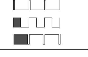
Pulse width modulation (PWM)
A signal consisting of variable width pulses at fixed intervals, whose ratio of "TIME ON" versus total "TIME
OFF" can be varied (also referred to as "duty cycle").
ON
10% Duty Cycle
OFF
ON
50% Duty Cycle
OFF
ON
90% Duty Cycle
OFF
TIME
Example of Pulse Width Modulation (PWM) Signals
Rated fuel limit
Indicates the maximum allowable fuel position (longest injection pulse). It will produce rated power for this
engine configuration.
Reference voltage
A regulated, unchanging voltage supplied by the ECM to a sensor. The reference voltage is used by the sensor
to generate a signal voltage.
Sensor
A device that is used to detect and convert a change in pressure, temperature, or mechanical movement into
an electrical signal.
Short circuit
A condition where an electrical circuit is unintentionally connected to an undesirable point. An example of a
short circuit is a wire which rubs against an engine frame until it eventually wears off its insulation and makes
electrical contact with the frame.
Subsystem
A part of the electronic system that relates to a particular function.
Supply voltage
A constant voltage supplied to a component to provide electrical power for its operation. It may be generated
by the ECM or may be battery voltage supplied by the equipment wiring.
System configuration parameters
Parameters that affect the power rating family or emissions.
"T" harness
A test harness that is designed to connect into the engine harness which allows normal circuit operation while
providing a breakout or "T" in order to measure signals.
Timing calibration
The adjustment of an electrical signal as a means of correcting the timing error between the crankshaft and
crankshaft position sensors.
Diagnostic Manual, TSD 3457E, Issue 2
7
This document is printed from SPI². Not for RESALE
![]()
![]()
![]()
1
2300 Series
TIPSS-EST
A service tool software program to run on a personal computer (PC).
Total tattletale
Total number of changes to all the customer specified parameters stored in the ECM.
8
Diagnostic Manual, TSD 3457E, Issue 2
This document is printed from SPI². Not for RESALE
![]()
![]()
![]()
2300 Series
2
Electronic system overview
2
System operation
The 2300 and 2800 Series industrial diesel engines are designed for electronic control. The injection pump,
fuel lines and nozzles used in mechanical engines have been replaced with an electronic unit injector in each
cylinder. A solenoid on each injector controls the amount of fuel that is delivered by the injector. An Engine
Control Module (ECM) sends a signal to each injector solenoid in order to provide complete control of the
engine.
Electronic controls
The electronic system consists of the Engine Control Module (ECM), the engine sensors and the OEM
interface. The ECM is the computer which controls the engine and contains the software which controls how
the ECM behaves and stores the operating maps that define power, rev/min, etc.
Engine governor
The electronic controls on the engine serve as the engine governor, determining when and how much fuel to
deliver to the cylinders based on the actual and desired conditions at any given time.
The ECM uses one of three possible speed control inputs to determine the desired engine speed and
compares this to the actual engine speed determined through the crankshaft position sensor. If the desired
engine speed is greater than the actual engine speed, more fuel is injected in order to increase engine speed.
Timing considerations
Once the ECM has determined how much fuel is required, it must next determine when to inject the fuel.
Injection timing is determined by the ECM after considering input from the following components:
Coolant temperature sensor
Intake manifold air temperature sensor
Atmospheric pressure sensor
Intake manifold pressure sensor
The ECM determines where top centre on cylinder number one is located from the engine camshaft position
sensor signal. The ECM decides when injection should occur relative to top centre and provides the signal to
the injector at the desired time. The ECM adjusts timing for the best engine performance, fuel economy and
white smoke control.
Note: Actual or desired timing cannot be viewed with the TIPSS-EST service tool.
Diagnostic Manual, TSD 3457E, Issue 2
9
This document is printed from SPI². Not for RESALE
![]()
![]()
![]()
![]()
![]()
![]()
![]()
2
2300 Series
Fuel injection
The ECM controls the amount of fuel injected by varying the signals to the injectors. The injectors will pump
fuel only if the injector solenoid is energized. The ECM sends a high voltage signal to energize the solenoid.
By controlling the timing and duration of the high voltage signal the ECM can control injection timing and the
amount of fuel that is injected.
The software inside the ECM sets certain limits on the amount of fuel that can be injected. The fuel limit is a
limit based on boost pressure to control the air/fuel ratio for control of emissions. When the ECM senses a
higher boost pressure (more air into cylinder) it increases the fuel limit (allows more fuel into cylinder).
The Rated Fuel Limit is a limit that is based on the power rating of the engine and engine rev/min. It is similar
to the rack stops and torque spring on a mechanically governed engine. It provides power and torque curves
for a specific engine family and rating.
Note: All of these limits are determined at the factory in the ECM software and cannot be changed.
10
Diagnostic Manual, TSD 3457E, Issue 2
This document is printed from SPI². Not for RESALE
![]()
![]()
![]()
2
2300 Series
Engine monitoring
Perkins provides a factory installed engine monitoring system. The Perkins engine monitoring system monitors
the following parameters:
Engine oil pressure
Coolant temperature
Intake manifold air temperature
Engine speed
Boost pressure
Fuel temperature
The Perkins engine monitoring system has three levels of operation, WARNING, ACTION ALERT and
SHUTDOWN as described below.
Perkins engine monitoring WARNING operation
In the WARNING condition the ECM causes the Warning lamp to turn ON to indicate a problem has been
detected by the Engine Monitoring System. No further ECM or engine action occurs.
Perkins engine monitoring ACTION ALERT operation
In the ACTION ALERT condition the ECM begins by activating the Action Alert lamp ON to indicate a problem
has been detected by the Engine Monitoring System. This is also normally wired to cause a shutdown via the
OEM control panel.
Perkins engine monitoring SHUTDOWN operation
If the fault reaches the SHUTDOWN condition the ECM activates the shutdown lamp and unless the engine is
in CRITICAL OVERRIDE condition, the engine will shutdown.
Fuel temperature monitoring
The fuel temperature sensor monitors the fuel temperature, adjusting the ECM calculated fuel rate to
compensate for fuel temperature changes and to adjust the fuel rate for constant power. The sensor is also
used to warn the operator of excessive fuel temperature with a diagnostic event code because excessive fuel
temperatures can adversely affect engine performance.
Self diagnostics
The electronic system has the ability to diagnose problems. When a problem is detected, a diagnostic code is
generated and stored in permanent memory (logged) in the ECM. The diagnostic lamp is also activated.
When diagnostic codes occur, the diagnostic codes are referred to as Active diagnostic codes. They indicate
that a problem of some kind currently exists.
Diagnostic codes that are stored in memory are called Logged diagnostic codes. Since the problem may have
been temporary, or may have been repaired since the problem was logged, logged codes do not necessarily
mean that something needs to be repaired. They are instead meant to be an indication of probable causes for
intermittent problems.
Diagnostic codes that identify operating conditions outside the normal operating range are called Events.
Event codes are not typically an indication of an electronic system problem.
Note: Some of the diagnostic codes require passwords to clear.
Diagnostic Manual, TSD 3457E, Issue 2
11
This document is printed from SPI². Not for RESALE
![]()
![]()
![]()
![]()
![]()
![]()
![]()
![]()
![]()
2
2300 Series
Effect of diagnostic codes on engine performance
The discussion on engine monitoring mentions that the diagnostic lamp activates when a specific condition
exists. When the ECM detects an engine problem, it generates an active diagnostic code and also logs the
diagnostic code in order to indicate when, and if appropriate, how many times the problem occurred. There are
two types of diagnostic codes, Fault codes and Event codes.
Diagnostic fault codes
These are provided in order to indicate that an electrical or electronic problem has been detected by the ECM.
In some cases the engine performance can be affected when the condition causing the code exists. More
frequently, however, no difference in the engine performance can be detected.
Diagnostic event codes
Diagnostic event codes are used to indicate that some operational problem has been detected in the engine
by the ECM. This usually does not indicate an electronic malfunction.
The ECM also provides an ECM clock with date/time to date and time stamp the following critical event codes:
360-3 Low oil pressure Shutdown
361-3 High coolant temperature Shutdown
For a listing all of the diagnostic fault codes, along with the page number where details regarding the cause,
performance effect, and diagnosis of the code can be located, refer to "Diagnostic code quick reference" on
page 80.
Current totals stored in the ECM
The ECM maintains engine total data for the following parameters:
Total time
The total time is the engine's operating hours. This does not include operating time when the ECM is powered
ON but the engine is not running.
Programmable parameters
Certain parameters affecting engine operation may be changed with the TIPSS-EST service tool. The
parameters are stored in the ECM, and are protected from unauthorized changes by passwords. These
parameters are either system configuration parameters or customer parameters.
System configuration parameters
These are set at the factory and affect emissions or power ratings within an engine family. Factory passwords
must be obtained and used to change the system configuration parameters.
Customer parameters
These are variable and can be used to tailor the engine to customer requirements within the limits set by the
factory and Perkins engine monitoring operation. Customer passwords may be required to change customer
parameters.
Caution: Some of the parameters may affect engine operation. Without adequate training, these parameters
may lead to power or performance complaints even when the engine is performing to specification.
Refer to "Programming parameters" on page 29 for further information.
12
Diagnostic Manual, TSD 3457E, Issue 2
This document is printed from SPI². Not for RESALE
![]()
![]()
![]()
![]()
![]()
2
2300 Series
Passwords
System configuration parameters are protected by factory passwords. Factory passwords are calculated on a
computer system that is available only to Perkins dealers.
Customer parameters can be protected by customer passwords. The customer passwords are programmed
by the customer. Factory passwords can be used to change customer passwords if they are lost.
Refer to "System configuration parameters" on page 30 for further information when passwords are needed
and how to obtain them.
Diagnostic Manual, TSD 3457E, Issue 2
13
This document is printed from SPI². Not for RESALE
![]()
![]()
![]()
2
2300 Series
Engine component diagram
Internal Injector Harness
12PIN Connector
Service
Tool
Connector
Interface
Connector
OEM Interface Connectors
Main Engine Harness
Crank Speed/Timing
Cam Speed/Timing
36-1 TOOTH
CRANK
GEAR
Inlet Manifold Temperature
Sensor
Fuel Temperature Sensor
36+1 TOOTH
CAM GEAR
Cooolat Temperature Sensor
Atmospheric Pressure Sensor
Boost
Pres Sensor
Calibration
Probe
Lub Oil Pressure
Sensor
A
HA0002
14
Diagnostic Manual, TSD 3457E, Issue 2
This document is printed from SPI². Not for RESALE
![]()
![]()
![]()

2
2300 Series
OEM connection diagram
To ECM J1 Connector
Customer connecter (If fitted)
E-Stop
16A Breaker
Service Tool
Connector
Keyswitch
Injector D, isable
Optional
24V
Digital Speed Control
Optional
Optional
Speed
Raise/Lower
Critical Override
Optional
Optional
Throttle Adjust Pot
Lamp Box
1: Diagnostics
2: Caution
3: Warning
Speed Control
4: Shutdown
5: Overspeed
6: High Coolant Temp
7: Low Pressure
1
2
3
Shutdown
Reset
Optional
droop
adjust
-B
S
D
+B
Switched
Battery +ve
Optional
Droop/Isoch
Optional
Potentiometer
0.5-4.5V
Speed
Selection
Optional
Screen tied to
ECM -VE
A
HA0003
Diagnostic Manual, TSD 3457E, Issue 2
15
This document is printed from SPI². Not for RESALE
![]()
![]()
![]()

2
2300 Series
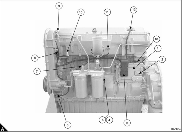
Sensor and connector location diagram
1 Electronic Control Module (ECM)
2 J1/P1 Machine connector
3 J2/P2 Engine connector
4 Atmospheric pressure sensor
5 Oil pressure sensor
6 Crankshaft position sensor
7 Fuel temperature sensor
8 Camshaft position sensor
9 Coolant temperature sensor
10 Intake manifold pressure sensor
11 Intake manifold air temperature sensor
12 Electronic unit injector connector
13 Timing calibration pickup connector
16
Diagnostic Manual, TSD 3457E, Issue 2
This document is printed from SPI². Not for RESALE
![]()
![]()
![]()
2
2300 Series
Engine wiring diagram
ECM
5
7
6
J2/44
J2/45
J2/46
J2/55
J2/54
J2/39
J2/38
J2/37
J2/36
Injector Common Cylinders 1 & 2
Injector Common Cylinders 3 & 4
Injector Common Cylinders 5 & 6
Injector Cylinder 6
Injector Cylinder 5
Injector Cylinder 4
Injector Cylinder 3
Injector Cylinder 2
Injector Cylinder 1
B
B
B
A
P
G
W
B
B
B
A
P
G
W
K
10
3
11
2
12
1
K
R
R
Injector
Cyl 1
Injector
Cyl 2
Injector
Cyl 3
Injector
Cyl 4
Injector
Cyl 5
Injector
Cyl 6
J300 P300
Atmospheric Pressure Sensor
+5V
Signal
Return
A
C
B
J2/2
J2/14
J2/3
+5VDC Supply
Atmospheric Pressure
Analogue Return
O
U
N
P203 J203
Intake Manifold Pressure Sensor
+5V
Signal
Return
A
C
B
Intake Manifold Pressure
J2/40
U
P200 J200
Oil Pressure Sensor
+5V
Signal
Return
A
C
B
J2/24
J2/32
J2/33
Oil Pressure
A
P201 J201
Coolant Temperature Sensor
Coolant Temperature
Signal
Return
C
B
U
J100 P100
Fuel Temperature Sensor
C
Fuel Temperature
Signal
Return
U
B
J105 P105
Inlet Air Temperature Sensor
Signal
Return
C
B
J2/35
J2/18
Inlet Air Temperature
Return
U
N
J103 P103
Crankshaft Position Sensor
Signal
Return
2
1
J2/48
J2/49
Crank Speed Timing +
Crank Speed Timing -
Y
U
J401 P401
Camshaft Position Sensor
Signal
Return
2
1
J2/58
J2/59
Cam Speed timing +
Cam speed timing -
Y
U
J402 P402
Calibration Probe
Signal
Return
1
2
J2/22
J2/23
Calibration Probe +
Calibration Probe -
Y
U
J400 P400
P2 J2
A
HA0005
Diagnostic Manual, TSD 3457E, Issue 2
17
This document is printed from SPI². Not for RESALE
![]()
![]()
![]()

2
2300 Series
Machine wiring diagram (all options)
This Wiring Supplied By OEM
Outputs may be used to
drive lamps or relays
Customer
Interface
Connector
J3 P3
11
ECM
Engine Running
Shutdown
Engine Running Output
J1/13
J1/10
W
G
16
5
Shutdown lamp Output
Action Alert Lamp Output
Warning Lamp Output
System Fault Lamp Output
Action Alert
J1/19
U
Warning
4
3
J1/20
J1/31
P
I
Diagnostics
Oil Pressure
8
J1/28
J1/29
Oil Pressure Lamp Output
O
N
Coolant Temp
17
Coolant Temperature Lamp Output
Overspeed Lamp Output
Overspeed
9
J1/30
J1/49
A
2
Digital Speed Control Enable
Injection Disable
Digital Speed
Control Enable
G
U
P
K
O
N
A
Y
34
J1/62
J1/59
Injection
Disable
29
35
Lower Speed
Lower
Speed
J1/64
J1/7
Shutdown Emergency Override
Raise Speed
Critical Override
28
Raise
Speed
25
26
18
12
J1/56
1500/1800 rpm Select
Droop/Isochronous
Fault Reset
1500/1800
rpm Select
J1/46
Droop/
Isochronous
J1/41
J1/18
Fault Reset
Digital Ground
- Battery
B
B
27
22
J1/67
J1/5
Ground
Ground
To PWM
Speed Control
(If Required)
B
PWM
36
21
J1/66
J1/4
PWM Input
+8V
W
R
+8V
23
20
680R
B
B
5K Analogue
Speed Setting
Potentiometer or
Input from Load
Sharer/Synchroniser
J1/3
Analogue Ground
Analogue Speed Input
+5V
24
19
38
J1/17
J1/2
W
R
B
680R
J1/61
J1/63
J1/65
J1/48
J1/52
J1/53
- Battery
- Battery
Charging
Alternator
39
B
- Battery
40
15
33
GRD
POS
B
Emergency
Stop Button
Unswitched + Battery
R
R
R
Unswitched + Battery
Unswitched + Battery
1
10
31
32
11
7
J1/70
J1/50
J1/34
J1/42
Switched + Battery
J1939 Data Link +
Key
Switch
Y
G
Circuit
Breaker
J1939
J1939 Data Link -
J1939 Screen
Data
Link
A
Starter
Motor
Perkins Data Link +
Perkins Data Link -
Perkins
Data
Link
J1/8
J1/9
G
6
Start
N
Button
J1/55
J1/69
Unswitched + Battery
- Battery
R
B
-
+
P1 J1
Battery
9 Pin Perkins Data
Link Connector
24V DC
J
H C G F
D E A B
A
HA0006
18
Diagnostic Manual, TSD 3457E, Issue 2
This document is printed from SPI². Not for RESALE
![]()
![]()
![]()

2
2300 Series
Electrical connectors and functions
Connector
Function
J1/P1
ECM connector (70-Pin OEM harness)
J2/P2
ECM connector (70-Pin Engine harness)
J3/P3
Machine wiring connector (40-Pin connector) - optional
Engine coolant temperature sensor (2-pin connector)
Engine intake manifold temperature sensor (2-pin connector)
Engine fuel temperature sensor (2-pin connector)
Engine intake manifold pressure sensor (3-pin connector)
Engine oil pressure sensor (3-pin connector)
J100/P100
J103/P103
J105/P105
J200/P200
J201/P201
J203/P203
J300/P300
J400/P400
J401/P401
J402/P402
Engine atmospheric pressure sensor connector (3-pin connector)
Injector solenoid harness (12-pin connector)
Engine timing calibration probe (2-pin connector)
Crankshaft position sensor (2-pin connector)
Camshaft position sensor (2-pin connector)
Colour codes
Key letter
Colour
Brown
Blue
N
U
R
P
Red
Purple
Green
White
Yellow
Black
Orange
Pink
G
W
Y
B
O
K
A
Grey
Diagnostic Manual, TSD 3457E, Issue 2
19
This document is printed from SPI². Not for RESALE
![]()
![]()
![]()


2
2300 Series
Service tools and diagnostics
The Perkins TIPSS-EST service tool is designed to help the service technician analyse and locate faults or
problems within the system. They are required to perform calibrations and to read or change engine
parameters.
Perkins TIPSS-EST is a software program that runs on a personal computer and requires a communication
adapter to translate information from the Perkins Data Link to the computer RS232 port.
Perkins TIPSS-EST can be used to display the following information:
Programmable parameter settings
Active and logged diagnostic codes
Logged events
Engine rating history
Histograms
Custom data
ECM date/time clock
Perkins TIPSS-EST can also be used to perform the following functions:
Diagnostic tests
Sensor calibrations
Flash programming
Parameter programming
Copy configuration (ECM replacement)
Data logging
Real time graphing
There are several adapter cables, breakout T cables, etc that are used in order to access measurements of
signals. A heavy duty multimeter is suitable in order to make the necessary measurements. A multimeter that
has the ability to measure duty cycle may also be required. Other special tools include those needed to
measure pressure and temperature. For further details refer to Chapter 5, Special tools.
A diagnostic code reader is also available. This is a hand held unit which allows reading certain parameters
and diagnostic codes.
20
Diagnostic Manual, TSD 3457E, Issue 2
This document is printed from SPI². Not for RESALE
![]()
![]()
![]()
![]()
![]()
![]()
![]()
![]()
![]()
![]()
![]()
![]()
![]()
![]()
![]()
![]()
![]()
2300 Series
3
Programming parameters
3
Connecting the TIPSS-EST
The communications adapter is powered by 24 Volts DC from the engine battery. This permits operation
beside the engine to allow use during engine operation.
Use the following procedures to connect the service tool to the engine.
1 Stop the engine by turning the key switch to the OFF position.
2 Connect the service tool harness cable on the engine to the communication adapter. Refer "Connecting
TIPSS-EST using a TIPSS communication adapter" on page 22.
3 Connect the communication adapter to the PC using the appropriate cable.
4 Turn the key switch to the ON position in order to begin testing. The service tool will operate while the engine
is running or with the engine OFF and the key switch ON. If the tool does not communicate with the ECM
disconnect and reconnect the diagnostics connector cable. Check the communication. If the problem is still
present refer to Test 45: Perkins Data Link circuit test on page 118.
Notes:
The service tool may restart during engine cranking due to a voltage dip on the battery line.
The TIPSS-EST must be configured to communicate with the specific type of communication adapter used.
Go to the "Preferences" menu that is located under "Utilities" in order to select the appropriate
communication adapter.
Diagnostic Manual, TSD 3457E, Issue 2
21
This document is printed from SPI². Not for RESALE
![]()
![]()
![]()
![]()
![]()
3
2300 Series
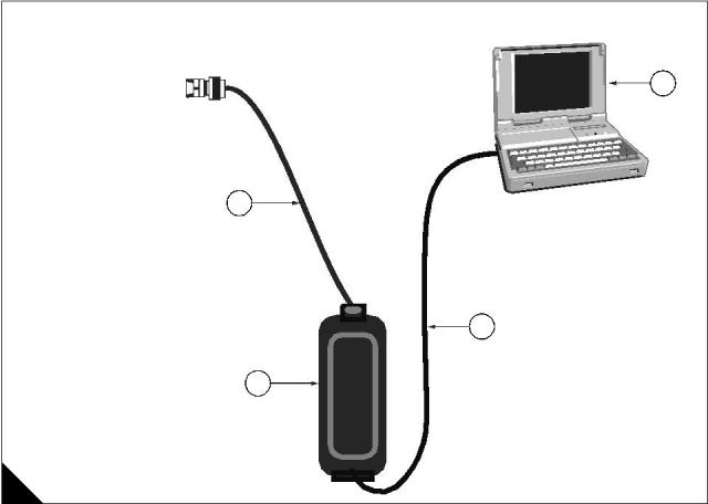
Connecting TIPSS-EST using a TIPSS communication adapter
1 PC with TIPSS-EST installed
2 PC to communication adapter cable (27610169)
3 Communication adapter (27610165)
4 Service tool harness cable (27610168)
1
4
2
3
A
HA0007
22
Diagnostic Manual, TSD 3457E, Issue 2
This document is printed from SPI². Not for RESALE
![]()
![]()
![]()
3
2300 Series
Passwords
Factory passwords
Factory passwords are required to perform each of the following functions:
1 Program a new ECM
When an ECM is replaced the system configuration parameters must be programmed into the new ECM. A
new ECM will allow these parameters to be programmed once without factory passwords. After the initial
programming these parameters are protected by factory passwords.
2 Rerate to another engine family
This requires changing the ECM software code, which is protected by factory passwords.
3 Read customer passwords
If the owner loses his customer passwords, he will not be able to program customer parameters. By using
factory passwords, one can read customer passwords, then use those customer passwords to program
customer parameters.
4 Clear certain diagnostic codes
Diagnostic code 253-02 Incorrect ECM software requires a factory password to clear the code. This diagnostic
code should be cleared only if you are certain that the ECM software is for the specific engine.
Caution: Operating the engine with ECM software not designed for that engine will result in engine damage.
Be sure the ECM software is correct for your engine.
5 Certain other codes require customer passwords. The majority of logged codes do not require passwords
to be cleared. To obtain factory passwords, proceed as if you already have the password. At some point, if the
factory passwords are actually needed, TIPSS-EST will request the factory passwords and display the
information required to obtain the passwords.
Customer passwords
If customer passwords have been entered, they are then required to change ANY customer parameter.
TIPSS-EST can be used to change customer parameters. To obtain customer passwords, contact the supplier
of the equipment. If the owner has lost the passwords, customer passwords may be read by using TIPSS-EST
(factory passwords are required in order to read customer passwords) by using the following procedure.
1 In TIPSS-EST access "Passwords" under the "Information" menu.
2 When the "Factory Password" screen appears, record the information listed.
3 Obtain the factory passwords. The information recorded above must be provided, and generates a
permanent record at Perkins of the access.
4 From the "Factory Password" screen, enter the factory passwords.
5 When the "View Customer Passwords" screen appears, record the customer passwords. The customer
passwords may then be used to change customer parameters.
Diagnostic Manual, TSD 3457E, Issue 2
23
This document is printed from SPI². Not for RESALE
![]()
![]()
![]()
3
2300 Series
Programming a new ECM
The Engine Control Module or ECM is the brain of the system. When a problem occurs, it is easy to assume
that the ECM is responsible. This is usually the wrong conclusion.
Most failures occur at the wiring and connectors or at a sensor input/output. Follow the diagnostic test
procedures and do not replace an ECM on speculation.
However, when your diagnosis indicates that a failure has in fact occurred in the ECM, the following procedure
outlines the steps required to replace a faulty ECM.
Note: If an ECM replacement is required, the ECM parameters and injector trim codes can be transferred from
the suspect ECM to the replacement ECM. This feature requires TIPSS-EST and is only possible if the suspect
ECM can communicate with the TIPSS-EST.
Replacing the ECM using TIPSS-EST ECM replacement feature
Note: The Test ECM referred to below is another identical ECM to that fitted to the engine. There is no special
Test ECM available.
1 Ensure that the ECM is the problem by first temporarily connecting a test ECM. Hang the test ECM on the
side of the engine. Flash program the identical software that was used in the suspect ECM into the test ECM.
Use the TIPSS-EST ECM replacement feature to copy the parameter configuration of the suspect ECM into
the test ECM. Ensure that the parameters in the test ECM are programmed the same as the parameters in the
suspect one.
2 If the test ECM repairs the problem, reconnect the suspect ECM. Check that the problem returns when the
suspect ECM is reconnected.
3 Select the ECM Replacement feature under the "Service/Copy Configuration" menu and load the
parameters from the failed ECM.
4 Temporarily connect the new ECM by connecting both ECM connectors. Do not mount the ECM on the
engine yet.
5 Flash program the ECM software into the new ECM if the software is not already installed.
Note: The new ECM may be shipped with no software installed or may have been pre-flashed at the factory.
Following reflashing the engine may be inoperable until a factory password has been obtained.
6 Use the TIPSS-EST ECM replacement feature to program the new ECM
7 Enter rating number parameter into the new ECM
8 Check for active codes. Program any required parameters that have not been programmed.
Note: On initial power-up of a new ECM, the Rating Number parameter must be programmed to avoid a
268-02 Check Programmable Parameters diagnostic code.
Install the new ECM on the engine and after checking for correct operation perform a timing calibration.
24
Diagnostic Manual, TSD 3457E, Issue 2
This document is printed from SPI². Not for RESALE
![]()
![]()
![]()
3
2300 Series
Replacing the ECM (if ECM replacement feature cannot be used)
1 Ensure that the ECM is the problem by first temporarily connecting a test ECM. Hang the test ECM on the
side of the engine. Flash program the identical software that was used in the suspect ECM into the test ECM.
Program any parameters that are necessary to use the ECM for the test. Program the parameters exactly the
same as they are in the suspect ECM.
2 If the test ECM repairs the problem, reconnect the suspect ECM. Check that the problem returns when the
suspect ECM is reconnected.
3 Obtain customer parameters from the failed ECM
Obtain and record the customer passwords. If the customer has lost or forgotten their passwords, obtain
factory passwords to get them.
Use TIPSS-EST to access customer specified parameters from the ECM that is being replaced. If the ECM
does not communicate with the electronic service tool, obtain the required parameter list from the OEM.
Record the customer parameters.
4 Record ECM current totals
5 Temporarily connect the new ECM by connecting both ECM connectors. Do not mount the ECM to the
engine until the timing calibration has been performed.
6 Flash program the software into the new ECM if the software is not already installed.
Note: The new ECM may be shipped with no software installed, or may have been pre-flashed at the factory.
7 Obtain factory passwords if required. The following parameters can be programmed once on a new ECM
without factory passwords:
Full Load Setting (FLS)
Full Torque Setting (FTS)
Engine serial number
System configuration parameters must be entered before the customer specified parameters are entered
If customer parameters are entered before the system configuration parameters, the total tattletale will change.
It will then be necessary to obtain another set of factory passwords in order to access system configuration
parameters.
8 Record the following information from the engine information plate:
Engine serial number
Obtain the following information from the factory:
Full Load Setting (FLS)
Full Torque Setting (FTS)
Injector Trim Codes
Use TIPSS-EST to access system configuration parameters. When the "Factory Specified Passwords" screen
appears record the following information:
ECM serial number
Engine serial number
TIPSS-EST serial number
Total tattletale
Reason code
Leave TIPSS-EST on the "Factory Specified Passwords" screen and obtain the factory passwords.
Continued
Diagnostic Manual, TSD 3457E, Issue 2
25
This document is printed from SPI². Not for RESALE
![]()
![]()
![]()
![]()
![]()
![]()
![]()
![]()
![]()
![]()
![]()
![]()
![]()
![]()
![]()
3
2300 Series
9 Program the new ECM
On initial powerup of a new ECM the following three parameters must be programmed to avoid a 268-02
Check Programmable Parameters diagnostic code:
Full Load Setting (FLS)
Full Torque Setting (FTS)
Engine serial number
Use TIPSS-EST to access system configuration parameters. Enter the recorded values for the following
parameters:
Full Load Setting (FLS)
Full Torque Setting (FTS)
Engine serial number
Injector trim codes
Use TIPSS-EST to access customer specified parameters. Enter the customer specified parameters and the
original customer passwords.
Use TIPSS-EST to access current totals from the "Read/Change Current Totals" main menu. Using the
recorded factory passwords enter the totals from the original ECM.
Use the "Service\Calibrations\Timing Calibration" menu to calibrate the timing. Refer to Test 46: Engine
speed/timing circuit test on page 126.
10 Install the new ECM on the engine.
26
Diagnostic Manual, TSD 3457E, Issue 2
This document is printed from SPI². Not for RESALE
![]()
![]()
![]()
![]()
![]()
![]()
![]()
![]()
![]()
![]()
![]()
3
2300 Series
Programming an ECM using flash programming
1 Connect the PC to the appropriate communication adapter and connect the communication adapter to the
ECM. Refer to "Connecting TIPSS-EST using a TIPSS communication adapter" on page 22.
2 Start the WinFlash PC Program.
3 Ensure that the key switch is ON and the engine is OFF.
4 Select the part number of the engine software that needs to be programmed into the ECM and proceed with
programming. A new ECM is shipped with no software loaded.
Note: The WinFlash PC program provides the ECM, application and software part number of the selected file.
Ensure that this file matches the engine before you begin to Flash the file into the ECM
PC program software messages and their meaning
A new ECM comes unprogrammed. An unprogrammed ECM will prompt you for all three of the following
messages. The information that is contained in the ECM Status will be scrambled and meaningless if the
module has not been programmed previously (this is normal).
Message: The engine ID in the flash file does not match the engine ID in the ECM
Meaning: The ECM has software for a different engine.
Solution: Stop the transfer and access information about the ECM Status under the "Electronic Control
Module" menu. Ensure that the file you are about to transfer matches the engine application.
Message: The application ID in the flash file does not match the application ID in the ECM
Meaning: The ECM has software for a different application.
Solution: Stop the transfer and access information about the ECM Status under the "Electronic Control
Module" menu. Ensure that the file you are about to transfer is for the correct engine type.
Message: The ID of the ECM in the flash file does not match the ID of the ECM in the ECM
Meaning: The ECM is not for use with this application.
Solution: Stop the transfer and access information about the ECM status under the "Electronic Control
Module" menu. Ensure that the ECM on the engine is for the correct application.
Note: If you access the ECM status under the "Engine Control Module" menu, but do not program the ECM,
complete the following procedure.
Turn the key switch to the OFF position, and then to the ON position before using TIPSS-EST. If the key switch
is not cycled after reading the ECM Status, the ECM will not communicate with your service tool or will not start.
Cycling the key switch is not necessary after the software has been successfully programmed using the
WinFlash program.
5 Start the engine and check for correct operation.
Program any parameters not previously in the old software if a 268-02 Check Programmable Parameters
diagnostic code is active. Read the diagnostic code from service tool "Active Diagnostic Code" screen in order
to determine the parameter(s) requiring programming.
On initial powerup of a new ECM three parameters must be programmed to avoid a 268-02 Check
Programmable Parameters diagnostic code:
Full Load Setting (FLS)
Full Torque Setting (FTS)
Engine serial number
Refer to "Programming a new ECM" on page 24.
Diagnostic Manual, TSD 3457E, Issue 2
27
This document is printed from SPI². Not for RESALE
![]()
![]()
![]()
![]()
![]()
![]()
3
2300 Series
ECM date/time clock
ECM date/time stamped information
The ECM date and time can be programmed with the TIPSS-EST service tool (factory passwords are required
to change these parameters). This will display the programmed date in month/day/year format and the
programmed time in hour:minute:second format. The tool has the option to program any date/time or
automatically select the date/time stored in the PC real time clock.
The date and time will remain programmed in the ECM even if the unswitched battery connections are
removed.
The ECM Date/time clock is used to stamp the following critical event codes:
360-3 Low oil pressure Shutdown
361-3 High coolant temperature Shutdown
Before adjusting the ECM date/time clock
Before adjusting the ECM date/time clock, ask the owner/operator if the time stamped information should be
recorded. After the time stamped information is recorded, clear this information before adjusting the ECM date/
time clock. This is a very important step if the adjustment of the clock is a big adjustment. This will prevent
unnecessary confusion if someone else views the information at a later date.
Determining time stamped information occurrence
When viewing time stamped information remember that someone may have incorrectly or never set the clock.
Use the time currently set in the ECM to compare any ECM recorded information to the time the ECM indicates
to determine how long ago the time stamped event occurred.
Caution: Do not replace an ECM because of an incorrect time.
The following example indicates the correct use of the clock.
Example use of ECM date/time stamped information
The TIPSS-EST service tool indicates a Low Oil Pressure occurred on NOV 19 1998 10:30:46 and that the
current time of day in the ECM is NOV 24 1998 11:20:58.
This indicates that the problem occurred approximately 5 days and 50 minutes ago.
Caution: Do not compare it to the current time at your location.
If the ECM time is significantly different than your current time, for example the wrong month is programmed,
ensure you have recorded the time stamped information if it is important. After recording the information, clear
the code and then adjust the clock.
28
Diagnostic Manual, TSD 3457E, Issue 2
This document is printed from SPI². Not for RESALE
![]()
![]()
![]()
![]()
![]()
3
2300 Series
ECM diagnostic clock
The diagnostic clock should not be confused with the ECM date/time clock. The diagnostic clock records the
actual hours the ECM has been powered (key switch ON and engine running). This information is maintained
even if the unswitched battery connections are removed. The clock information is used to log diagnostic code
and event code occurrences. Logged diagnostic codes and event codes display the diagnostic clock hour of
the first and last occurrence and the total number of occurrences.
Note: Actual engine running hours (total time) can be obtained from the "Current Totals" menu of TIPSS-EST.
Injector codes
Injector codes are etched on each injector. The injector codes can be viewed/changed using TIPSS-EST by
selecting the "Calibrations" screen under the "Service" menu. The injector codes calibration is located under
the "Calibration" menu. The injector code must match the code on the corresponding injector. When an injector
is replaced, reprogram the new code for the new injector.
TIPSS-EST cylinder cut-out test
The 2300 and 2800 Series engines use electronic fuel injectors. These injectors are mechanically actuated
and electronically energized. The cylinder cut-out tests are used to confirm that the cylinders are functioning
correctly.
The cylinder cut-out test allows a specific cylinder to be cut out while the fuel position is monitored for the
remaining cylinders.
To perform a cylinder cut-out test, connect TIPSS-EST to the diagnostic connector as described in
"Connecting the TIPSS-EST" on page 21, and select the Cylinder cut-out test located under the "Diagnostics"
menu.
The Cylinder cut-out test opens with the manual test. At the bottom of the TIPSS-EST screen there is a row of
buttons that function as follows:
Change toggles the highlighted cylinder between powered and not powered
Power All returns all cylinders to the normal operating state
Start initiates the automated Cylinder cut-out test.
Stop terminates the automated test.
Results displays the test results.
Print allows the contents of the screen to be previewed or to be sent to a file or printer.
Programming parameters
Many programmable parameters affect engine operation. These parameters may be changed by using the
TIPSS-EST service tool. The parameters are stored in the ECM. Whilst any parameter can be read, passwords
can be used to protect parameters from unauthorized changes.
Two categories contain these various parameters:
System configuration parameters
System configuration parameters can only be altered with factory passwords by using TIPSS-EST.
Customer specified parameters
Customer specified parameters can be changed by using the TIPSS-EST service tool (this may require
customer passwords if customer passwords have been programmed). Refer to "Passwords" on page 13 for
more details on how to receive and use factory and customer passwords.
Diagnostic Manual, TSD 3457E, Issue 2
29
This document is printed from SPI². Not for RESALE
![]()
![]()
![]()
![]()
![]()
![]()
![]()
![]()
![]()
3
2300 Series
System configuration parameters
System configuration parameters affect critical settings for the engine. They are programmed at the factory
and would normally never need to be changed through the life of the engine. A complete list of these
parameters is given in the table on the following page.
Note: System Configuration Parameters must be reprogrammed if an ECM is replaced. Failure to programme
these parameters will result in a 268-02 Check Programmable Parameters diagnostic code.
Proper values for these parameters are stamped on the engine information ratings plate located on the valve
cover or air inlet manifold. Factory passwords are required to change these parameters. The following
information is a description of the system configuration parameters.
Full Load Setting (FLS)
Number representing fuel system adjustment made at the factory to “fine tune” the fuel system. The correct
value for this parameter is stamped on the engine information ratings plate. A new ECM requires this
parameter to be programmed to avoid generating a 268-02 Check Programmable Parameters diagnostic code.
Full Torque Setting (FTS)
Similar to Full Load Setting. This parameter must be programmed to avoid generating a 268-02 Check
Programmable Parameters diagnostic code.
Software part number
This is the part number of the software flashed into the ECM.
Engine serial number
This should be programmed to match the engine serial number that is stamped on the engine information plate.
A new ECM is delivered without the engine serial number programmed.
ECM serial number
This is a read-only parameter which displays the serial number of the ECM.
Software release date
This parameter is defined by the ECM software and is not programmable. It is used to provide the version of
the software. Customer parameters software changes can be tracked by this date. The date is provided in the
month and year (NOV99), where NOV is the month (November) and 99 is the year (1999).
Critical override switch installed
The critical override switch, if fitted and enabled, allows the engine to continue running even if engine oil
pressure or coolant temperature have reached the limits where the engine would normally be shutdown. If the
engine is run in this condition, the engine warranty is void and any events occurring are stored in the ECM with
time and date stamping. Implementation of this facility requires a factory password.
Total tattletale
Displays the total number of times the configuration parameters have been changed.
30
Diagnostic Manual, TSD 3457E, Issue 2
This document is printed from SPI². Not for RESALE
![]()
![]()
![]()
3
2300 Series
Configuration parameters
Configuration Parameter Description
R/W Security
Selected Engine Rating
Rating Number
Customer
Rated Frequency
Read Only
Read Only
Read Only
Read Only
Read Only
Customer
Rated Genset Speed
Rated Real Genset Power
Rated Apparent Genset Power
Engine Rating Application Type
External Speed Selection Switch Installed
ECM Identification Parameters
Equipment ID
Customer
Factory
Engine Serial Number
ECM Serial Number
Read Only
Read Only
Read Only
Read Only
ECM Software Part Number
ECM Software Release Date
ECM Software Description
Security Access Parameters
Total Tattletale
Read Only
Engine/Gear Parameters
Engine Acceleration. Rate
Droop/Isochronous Switch Installed
Droop/Isochronous Selection
Engine Speed Droop
Customer
Customer
Customer
Customer
Factory
Critical Override Switch Installed
Digital Speed Control Installed
Speed Control Min Speed
Speed Control Max Speed
Digital Speed Control Ramp Rate
Crank Terminate Speed
I/O Configuration Parameters
Desired speed Arrangement
System Parameters
Customer
Customer
Customer
Customer
Customer
Customer
FLS
Factory
Factory
None
FTS
Governor ProportionalGain
Governor Minimum Stability Factor
Governor Maximum Stability Factor
Passwords
None
None
Customer Password 1
Customer
Customer
Customer Password 2
Diagnostic Manual, TSD 3457E, Issue 2
31
This document is printed from SPI². Not for RESALE
![]()
![]()
![]()

3
2300 Series
Customer specified parameters
Customer specified parameters allow the OEM to modify engine parameters to suit the application.
Customer parameters may be changed repeatedly as a customer changes his requirements. Customer
passwords are required to change these parameters.
The following information is a brief description of the customer specified parameters.
Rating duty selection
This enables selection of the engine rating from a series of maps within the ECM. Changing the rating requires
a customer password. The available ratings within the ECM will vary with engine type and specification.
Rated frequency
This displays the rated frequency of the set, i.e. 50 Hz or 60 Hz, determined by the rating selection and the
status of the external speed selection switch. This parameter is read only.
Rated speed
This displays the rated speed of the engine, i.e. 1500 rev/min or 1800 rev/min, determined by the rating
selection and the status of the external speed selection switch. This parameter is read only.
Rated real genset power
This displays the maximum power in kW of the currently selected rating. This parameter is read only.
Rated apparent genset power
This displays the maximum power in kVA of the currently selected rating. This parameter is read only.
Rating configuration
This displays the configuration of the currently selected rating. The possible configurations are:
Standby power
Limited time prime power
Prime power
Continuous or baseload power
For definitions of these ratings, refer to ISO8528. This parameter is read only.
Note: Not all of the above rating configurations will be available in a given ECM software file.
External speed selection switch enable
For dual speed (1500 rev/min or 1800 rev/min) applications, where an external speed selection switch is
required, this parameter enables the functionality of the speed selection switch within the software. Changing
this parameter requires a customer password.
Engine startup acceleration rate
Enables the acceleration rate of the engine in rev/min/s, from idle speed to rated speed, to be programmed.
Control of this parameter enables any overshoot in speed on start up to be limited. Changing this parameter
requires a customer password.
Droop/isochronous switch enable
Determines whether the external droop/isochronous switch is enabled or disabled. Changing this parameter
requires a customer password.
Droop/isochronous selection
The engine will normally be run in isochronous mode i.e. the engine speed is the same at all loads. For certain
applications where parallel operation with another generating set or with the grid is required, it is necessary for
stability reasons to run in droop condition where engine speed drops with load. This parameter enables droop/
isochronous running selection. Changing this parameter requires a customer password.
Note: , If an external droop/isochronous switch is enabled, the position of this switch will over-ride the Droop/
Isochronous selection.
32
Diagnostic Manual, TSD 3457E, Issue 2
This document is printed from SPI². Not for RESALE
![]()
![]()
![]()
![]()
![]()
![]()
![]()
3
2300 Series
Engine speed droop
If droop operation is selected, this parameter allows the setting of percentage droop i.e. the percentage that
the engine speed will drop with load. This parameter has no effect when the engine is running in isochronous
mode. Changing this parameter requires a customer password.
Digital speed control installed
This parameter determines whether raise/lower switch input control of engine speed is installed. If digital speed
control is not installed, speed control reverts to the analogue or PWM inputs depending on which input is
selected via the desired speed input configuration detailed on the following page. Changing this parameter
requires a customer password.
Digital speed control min speed
This setting determines the minimum speed range of both the raise/lower button control and the analogue
control, for example: if this is set to 100 rev/min and the nominal engine speed is selected for 1500 rev/min,
the minimum speed setting is 1400 rev/min. It does not affect the PWM speed control range which has fixed
min/max limits. Changing this parameter requires a customer password.
Digital speed control max speed
This setting determines the maximum speed range of both the raise/lower button control and the analogue
control, i.e. if this is set to 100 rev/min and the nominal engine speed is selected for 1500 rev/min, the
maximum speed setting is 1600 rev/min. It does not affect the PWM speed control range which has fixed min/
max limits. Changing this parameter requires a customer password.
Digital speed control ramp rate
This setting determines the rate of change of engine speed in rev/min/s when the raise/lower switch inputs are
closed. Changing this parameter requires a customer password.
Crank terminate speed
This parameter is used to set the engine speed at which the crank terminate relay output will be switched.
Changing this parameter requires a customer password.
Desired speed input arrangement
This parameter allows selection of the analogue or PWM external speed control if the digital speed control is
not installed. The Analogue or PWM speed control inputs are normally used with generating set load sharing
and synchronising controllers. Changing this parameter requires a customer password.
Note: If PWM or Analogue speed control is selected but there are no inputs to the selected speed control
terminals, the engine will default to running at 1100 rev/min.
If it is not intended to use PWM or analogue speed control then the Digital speed control should be selected.
Governor gain parameters
The adjustable Governor Gain parameters are:
Governor Gain Factor
Governor Minimum Stability Factor
Governor Maximum Stability
Notes:
No engineering units associated with these numbers.
The programmable range is wide for flexibility. The values are valid from 1- 40000. This wide programmable
range may not be fully used on any system. Do not expect to use the whole range.
Diagnostic Manual, TSD 3457E, Issue 2
33
This document is printed from SPI². Not for RESALE
![]()
![]()
![]()
![]()
![]()
![]()
![]()
![]()
3
2300 Series
Gain explanations
Governor gain factor
The governor gain factor is multiplied to the difference between desired speed and actual speed.
If the governor gain factor value is too large, the engine speed can overshoot the desired speed. The
overshoot is caused by an overcorrection or a steady state instability.
If the governor gain factor is too small, the response necessary to accelerate the engine to the desired
speed must be obtained by ramping the stability terms to a higher value. This process is time consuming
so, as a result, the engine speed is slow to respond.
Governor minimum/maximum stability factor
The stability factor terms work to eliminate a steady state speed error. There are two gain terms used for
stability. If the error is greater than 20 rev/min and the error is increasing, then the maximum stability gain is
functioning. If the error is less than 20 rev/min, then the minimum stability gain is used. This function allows
the use of a high gain that would otherwise cause the engine to be unstable when the engine is operating near
the desired speed.
If either the minimum stability gain or the maximum stability gain is set too high, the governor will provide
more fuel than is necessary to bring the error to zero. The additional fuel will cause the engine speed to
overshoot and ring.
If either the minimum stability gain or the maximum stability gain is set too low, the engine will take too long
to arrive at a steady state speed.
Tuning procedure
1 Turn the key switch to the OFF/RESET position. Connect the TIPSS-EST service tool and check that engine
overspeed protection is enabled before beginning the tuning process. Engine overspeed is configured on the
"Service\Monitoring System" screen on TIPSS-EST.
Warning! Performing engine governor tuning without engine overspeed protection could result in serious
engine damage. Ensure that this parameter is ON while performing this procedure.
2 Start the engine. Observe, on the engine mounted genset control panel, that the engine has reached rated
speed. This panel will serve as the speed reference point during this procedure.
3 Enter the "Configuration Parameters" screen on TIPSS-EST.
4 Determine the desired scenario to tune the engine. For example, is the engine having poor response during
specific load assignments or specific load dumps ?
5 Perform the desired load change from step 4. Observe the response of the engine by viewing the engine
speed on the genset mounted control panel, by looking at the system bus frequency response to the load
change, or by listening to the response of the engine.
6 Use the suggestions listed above to determine which gains should be adjusted.
Note: Usually, the governor gain factor should be somewhat lower that the governor minimum stability factor
for optimum performance. The maximum stability factor is typically a smaller value than the minimum stability
gain and governor gain factor.
7 Repeat steps 5,6, and 7 until a desired engine response can be met. Use large adjustments (10% of original
gain) at first to generally tune the engine in the proper manner. As the response is closer to desired, increase
the gains in smaller increments (1% of total gain).
Customer password 1, customer password 2
These are the customer password programmable parameters that can be used to protect certain configuration
parameters from unauthorised changes.
34
Diagnostic Manual, TSD 3457E, Issue 2
This document is printed from SPI². Not for RESALE
![]()
![]()
![]()
![]()
![]()
![]()
![]()
2300 Series
4
Fault diagnosis
4
Introduction
This chapter has information that will assist with the diagnosis of mechanical and electronic faults on the
engine, and its management system.
The diagnostic process
Some engine symptoms are caused by conditions or components other than the electronic control system,
such as poor fuel quality or incorrectly adjusted valves.
The basic philosophy of diagnosing this engine is to follow the three steps listed below FIRST to diagnose a
malfunctioning engine:
1 Gather operator information. Check that the fault is not due to normal engine operation.
2 Perform a visual inspection of the engine. Check fuel and oil level, supply and/or condition. Check for visible
wiring and connector problems or damaged components.
3 Check and repair all ACTIVE/LOGGED diagnostic codes using the diagnostic procedures given in
"Diagnostic procedures with a diagnostic fault code" on page 76.
If ALL three of these inspections reveal no problems, identify probable causes using the procedure or
procedures in this chapter that best describes the symptoms. Narrow the probable causes given in the
procedure by considering operator information, operating conditions, and repair history of the engine.
Operator information
What happened, and when ?
Under what conditions ?
Was the engine rev/min (speed) high or low ?
Was the engine under load ?
Are there any customer or dealer installed systems that could cause this symptom ?
What else occurred ?
When did the symptoms begin (and what else happened at that time) ?
Logged diagnostic codes
Do they correlate to probable causes ?
Did they occur at the same time as the symptoms ?
Are some codes logged repeatedly ?
Other symptoms
Are they related to this symptom ?
Do they have common probable causes ?
Finally, test each probable cause using the tests suggested by the procedure
Be sure to check connectors, especially on intermittent problems. Refer to Test 39: Inspecting electrical
connectors on page 82 for details.
Diagnostic Manual, TSD 3457E, Issue 2
35
This document is printed from SPI². Not for RESALE
![]()
![]()
![]()
![]()
![]()
![]()
![]()
![]()
![]()
![]()
![]()
![]()
![]()
![]()
![]()
4
2300 Series
Diagnostic procedures without a diagnostic fault code
General information
This section is to be used for diagnosing problems that have symptoms but do not have ACTIVE diagnostic
codes.
Before using this section, be sure that you have gathered information about the fault to adequately describe
the symptoms, verified that the fault is not due to normal engine operation and repaired all ACTIVE diagnostic
codes. Refer to "Diagnostic procedures with a diagnostic fault code" on page 76.
36
Diagnostic Manual, TSD 3457E, Issue 2
This document is printed from SPI². Not for RESALE
![]()
![]()
![]()
4
2300 Series
Diagnostic symptoms
Engine will not crank
Test 1
Note: This is NOT an electronic system problem, the engine starter motor wiring is not supplied by Perkins.
Refer to the Workshop Manual and OEM Manual for additional information on the following tests.
Probable root causes
Battery cables/batteries
Emergency stop switch
Starter motor solenoid or circuit problem (in system wiring)
Starter motor/flywheel ring gear
Engine accessory
Hydraulic cylinder lock
Internal engine problem
Perform the following tests
1 Check battery post and battery cables for loose connections and corrosion. If corroded, remove and clean
cables and connections. Check the optional battery disconnect switch.
2 Check that the optional emergency stop switch is not engaged. Load test batteries. If necessary, charge the
batteries.
3 Test starter motor solenoid operation. Check the system wiring to starter motor solenoid.
4 Test starter motor operation. Inspect starter motor pinion and ring gear for damage.
5 Check that the timing pin was not left in the flywheel housing after setting valve clearances. Use the engine
turning tool and attempt to manually turn the engine. If unable to turn the engine, remove and inspect engine
accessories that can lock up the engine. Repair or renew as necessary.
6 Remove injectors and check for fluid in the cylinders.
7 Disassemble engine to inspect for internal components that may be seized, broken, bent, out of alignment,
etc. Refer to the Workshop Manual.
Diagnostic Manual, TSD 3457E, Issue 2
37
This document is printed from SPI². Not for RESALE
![]()
![]()
![]()
![]()
![]()
![]()
![]()
![]()
![]()
![]()
![]()
![]()
4
2300 Series
Engine cranks but will not start
Test 2
Probable root causes
Starting aids/fuel waxing (cold temperature operation)
Electrical connectors and wiring
ECM software or ECM
Engine speed/timing signal
Electrical connections to the unit injector solenoids
Fuel supply
Restriction of the air supply or exhaust
Combustion problem
Perform the following tests
1 If cold ambient conditions exist, check operation of starting aids. Check the coolant immersion heater for
malfunction and replace if required. Check for presence of congealed fuel (wax). Repair as required.
2 Check that the keyswitch and Injection Disable switches are closed.
3 Check for correct installation of the ECM connectors J1/P1 and J2/P2, engine speed/timing sensor
connectors J401/P401 and J402/P402, and unit injector connectors J300/P300. Check that the ECM is
receiving the correct voltage.
Note: Aftermarket engine protection devices may interrupt power to the ECM and prevent communications
with the TIPSS-EST service tool. Check for correct installation and operation of aftermarket engine protection
devices. Aftermarket devices may need to be bypassed to continue.
4 If the engine has an unprogrammed ECM it will crank but will not start. Access ECM Status in the WinFlash
PC program and follow the request to program the software. Refer to "Programming an ECM using flash
programming" on page 27. Failure to program the software will cause the engine to not start or communicate.
Cycling the key switch will allow access to the WinFlash PC program.
5 Check that none of the diagnostic lamps are illuminated. If any are, turn the key switch OFF and ON to try
and clear the fault. If the diagnostic lamps cannot be cleared refer to "Diagnostic procedures with a diagnostic
fault code" on page 76. Check that the speed/timing sensors are correctly installed and that no diagnostic
codes are active.
6 Check that there is not an active 268-02 Check Programmable Parameters diagnostic code. If the diagnostic
code is present, refer to "Programming an ECM using flash programming" on page 27.
7 Observe the engine speed on the TIPSS-EST "Status" screen while cranking the engine. If the electronic
service tool displays 0 rev/min while cranking the engine, there is a problem in the engine speed/timing sensor
circuit. Refer to Test 46: Engine speed/timing circuit test on page 126.
If the engine speed is greater than 50 rev/min the engine speed/timing circuitry appears to be operating
correctly. Check that the timing reference gear is installed correctly and keyed to the camshaft by means of
the locating dowel. If the gear was installed backwards or flipped over during assembly, the engine will not
start.
8 Check the calibration of the timing sensor and recalibrate if required. Refer to Test 47: Engine speed/timing
calibration on page 134. Check for correct orientation between crankshaft and camshaft drive gears, repair as
required.
9 Ensure the unit injector connectors are correctly installed. Refer to Test 48: Injector solenoids circuit test on
page 138 and perform the Injector Solenoid test as a quick check to confirm that the ECM can energize the
unit injector solenoids. Ensure that the injection disable switch (if fitted) is ON.
10 Check for a fuel supply problem and check fuel pressure. Refer to Test 29: Engine has a fuel supply
problem on page 65.
11 Check for combustion problems.
38
Diagnostic Manual, TSD 3457E, Issue 2
This document is printed from SPI². Not for RESALE
![]()
![]()
![]()
![]()
![]()
![]()
![]()
![]()
![]()
![]()
![]()
![]()
![]()
4
2300 Series
Engine misfires, runs rough or is unstable
Test 3
Note: If the problem is intermittent and cannot be recreated, refer to Test 6: Intermittent low power or power
cut-outs on page 42. If the problem is consistent and can be recreated, continue with this procedure.
Probable root causes
Cold mode operation (normal operation, if the problem occurs only after start-up)
Battery cables, battery
Electrical connections to the ECM
Loss of backup engine speed/timing sensor
Throttle position signal
Faulty electronic unit injector circuit (individual cylinder malfunction)
Fuel supply
Air inlet or exhaust restrictions or air system leaks
Internal engine problem
Note: If the problem only occurs under certain conditions (high engine speed, full load or engine operating
temperature, etc), then perform the test under those operating conditions.
Perform the following tests
1 Check indicator lamps; refer to Test 39: Inspecting electrical connectors on page 82.
2 Check for a fuel supply problem and check fuel pressure.
3 Check air inlet and exhaust systems for restrictions and leaks. Look for a diagnostic lamp indication, or
tripped restriction indicators (if fitted) associated with plugged air filters. Replace plugged air filters, or clean
filters, as described in the User’s Handbook, and repair any leaks found. Also refer to Test 41: Analogue
sensor open or short circuit test on page 91. Refer to the Workshop Manual if an internal engine problem is
suspected.
4 Monitor the TIPSS-EST "Status" screen to check that the engine has exited cold mode and observe the
coolant temperature reading on the electronic service tool. The engine should exit cold mode operation
whenever the coolant temperature is above 17 °C (64 °F) and the engine has been running for five minutes.
5 Check battery post and battery cables for loose connections and corrosion. If corroded, remove and clean
cables and connections.
6 Check the ECM connectors J1/P1 and J2/P2, customer connector, engine speed/timing sensor connectors,
unit injector connectors and associated wiring for damage, abrasion or incorrect attachment. Refer to Test 39:
Inspecting electrical connectors on page 82.
7 Check the battery connection at the customer connector and ECM connector. Perform a pull test on the
customer connector. Perform a pull test on P1 pins 48, 52, 53, 61, 63, 65 and 70. The wires should remain in
the connectors during pull test. Refer to Test 39: Inspecting electrical connectors on page 82.
8 Check that a 190-11 Loss of Engine Speed Signal diagnostic code is not active. If the 190-11 code is active
check to see if a 342-11 Loss of Backup Engine Speed Sensor diagnostic code has been recently logged. If
the electronic service tool indicates that a 342-11 code has been recently logged perform a pull test on the
wires to the backup engine speed/timing sensor. Refer to Test 39: Inspecting electrical connectors on page
82. If a 342-11 code has not been recently logged and the 190-11 code is active refer to Test 46: Engine
speed/timing circuit test on page 126.
9 Connect an electronic service tool to the service tool connector. Turn the key switch to the ON position,
engine OFF. If a PWM speed control is fitted, check that a 91-08 Invalid PWM Speed Control Signal diagnostic
code has not been recently logged. Monitor the throttle position from low idle to full throttle.
10 Check for active or recently logged injector solenoid diagnostic codes. Use an electronic service tool and
cut out each cylinder at low idle to isolate the misfiring cylinder(s). Refer to Test 48: Injector solenoids circuit
test on page 138.
Diagnostic Manual, TSD 3457E, Issue 2
39
This document is printed from SPI². Not for RESALE
![]()
![]()
![]()
![]()
![]()
![]()
![]()
![]()
![]()
![]()
![]()
![]()
![]()
![]()
4
2300 Series
Low power/poor or no response to throttle
Test 4
Probable root causes
Customer specified parameters
Cold mode operation (normal operation if the problem occurs only after start-up in cold weather)
Engine is in a derated mode
Electrical connections to the ECM
External speed control
Faulty electronic unit injector (individual cylinder malfunction)
Fuel supply
Intake manifold sensor signal
Air inlet or exhaust system restrictions or leaks
Incorrect adjustment of full load setting or full torque setting
Note: If the problem only occurs under certain conditions (high engine speed, full load or engine operating
temperature, etc), then perform the test under those operating conditions.
Perform the following tests
1 Check for a fuel supply problem and check fuel pressure. Refer to Test 29: Engine has a fuel supply problem
on page 65.
2 Check air inlet and exhaust systems for restrictions and leaks. Look for a diagnostic lamp indication, or
tripped restriction indicators (if fitted) associated with plugged air filters. Replace plugged air filters, or clean
filters, as described in the User’s Handbook, and repair any leaks found.
3 Check that the fault is not normal (programmed parameter) operation. Connect an electronic service tool
and check the system/customer parameters. If a 268-02 Check Customer Or System Parameters diagnostic
code is active, ensure ALL the system and customer parameters are programmed. Check that the injector
codes are programmed. Check that the correct rating is programmed.
4 Monitor the electronic service tool "Status" screen to check that the engine has exited cold mode. Observe
the coolant temperature reading on the electronic service tool. The engine should exit cold mode operation
whenever the coolant temperature is above 17 °C (64 °F) and the engine has been running for five minutes.
5 The engine may be derated due to altitude or other factors. Connect an electronic service tool and check for
active engine derates or diagnostic codes.
6 Check the ECM connectors J1/P1 and J2/P2, customer connector and the relevant speed setting inputs and
associated wiring for damage, abrasion or incorrect attachment. Refer to Test 39: Inspecting electrical
connectors on page 82.
7 If a PWM speed control is fitted, connect an electronic service tool to the service tool connector. Turn the
key switch to the ON position, engine OFF. Check that a 91-08 Invalid PWM Speed Control Signal diagnostic
code has not been recently logged. Monitor the PWM input. The duty cycle should be between 5 and 10
percent at low load and increase at full load. If the throttle position change is erratic or out of range the problem
is with the external speed control.
8 Check that a 262-03 +5 V Supply Above Normal or a 262-04 +5 V Supply Below Normal diagnostic code is
not present. If either of the codes are active refer to Test 41: Analogue sensor open or short circuit test on
page 91.
40
Diagnostic Manual, TSD 3457E, Issue 2
This document is printed from SPI². Not for RESALE
![]()
![]()
![]()
![]()
![]()
![]()
![]()
![]()
![]()
![]()
![]()
![]()
![]()
![]()
![]()
4
2300 Series
Intermittent engine shutdowns
Test 5
Note: Use this procedure only if the engine has shut down completely and has had to be restarted.
Probable root causes
Customer specified parameters
Electrical connections to the ECM
Faulty electronic unit injector connector
Engine fault
The ECM detects an engine fault, e.g. low oil pressure, etc. These fault codes may be viewed on the display
modules or an electronic service tool. They are logged in memory except as noted.
Note: If the problem only occurs under certain conditions (high engine speed, full load or engine operating
temperature, etc), then perform the test under those operating conditions.
Perform the following tests
1 The engine may be shut down due to low pressure levels, or other factors. Connect an electronic service
tool and check for active engine derates or diagnostic codes.
2 Check the ECM connectors J1/P1 and J2/P2, customer connector, engine speed/timing sensor connectors
and the unit injector connectors and associated wiring for damage, abrasion, corrosion or incorrect attachment.
Refer to Test 39: Inspecting electrical connectors on page 82 for additional information.
3 Check the electronic service tool for a logged 168-02 Intermittent Battery Power to the ECM diagnostic code.
Check the battery connection at the customer connector and the ECM connector. Refer to the electrical
schematic. Perform a pull test on the customer connector. Perform a pull test on P1 pins 48, 52, 53, 61, 63, 65
and 70. The wires should remain in the connectors during the pull test. Refer to Test 39: Inspecting electrical
connectors on page 82.
4 If the problem occurs only after the engine is warmed up and disappears after the engine has been allowed
to cool, the circuit breakers may be exceeding the trip point because of overheating. Check the circuit breakers
on the engine, reset if required.
Note: Aftermarket engine protection devices may interrupt power to the ECM. Check for correct installation
and operation of aftermarket engine protection devices. Aftermarket devices may need to be bypassed to
continue testing.
5 Check switch status on an electronic service tool. If the switch status is incorrect, refer to "Machine wiring
diagram (all options)" on page 18.
6 Check for a fuel supply problem and check fuel pressure. Refer to Test 29: Engine has a fuel supply problem
on page 65.
免费热线
400-100-8969 15088860848
400-100-8969 15088860848
机组销售
0574-26871589 15267810868
0574-26871589 15267810868
配件销售
0574-26886646 15706865167
0574-26886646 15706865167
维修热线
0574-26871569 18658287286
0574-26871569 18658287286
手机端

微信公众号