 English
 Espaol
 Franais
 阿拉伯
阿拉伯 中文(简)
中文(简) Deutsch
 Italiano
 Português
 日本
日本 韩国
韩国 български
 hrvatski
 esky
esky Dansk
Dansk Nederlands
 suomi
suomi Ελληνικ
 印度
印度 norsk
norsk Polski
 Roman
Roman русский
 Svenska
 John Deere约翰迪尔强鹿柴油发动机摇臂总成的安装方法,John Deere约翰迪尔强鹿柴油发动机摇臂总成的安装方法技术支持,John Deere约翰迪尔强鹿柴油发动机摇臂总成的安装方法费用,John Deere约翰迪尔强鹿柴油发动机摇臂总成的安装方法服务中心,John Deere约翰迪尔强鹿柴油发动机摇臂总成的安装方法价格规格资料查询,John Deere约翰迪尔强鹿柴油发动机摇臂总成的安装方法哪里有,John Deere约翰迪尔强鹿柴油发动机摇臂总成的安装方法多少钱,John Deere约翰迪尔强鹿柴油发动机摇臂总成的安装方法附近联系电话,宁波日昕动力科技有限公司

John Deere约翰迪尔强鹿柴油发动机摇臂总成的安装方法
详细描述
John Deere约翰迪尔强鹿柴油发动机摇臂总成的安装方法
1. Install push rods in same location from which removed.NOTE: Valve stem tips are specially hardened; wear capsare not required.
IMPORTANT: Relieve tension on rocker arm adjustingscrew to avoid damaging rocker armshaft during installation.
2. Position rocker arm assembly on engine.
IMPORTANT: Oil supply hole in rocker arm shaftmust be positioned at the flywheel endof engine and facing downward whenrocker shaft is installed.
3. Lubricate all rocker arms with engine oil and makesure they move freely. Tighten rocker arm supportstuds in a criss-cross sequence to specifications.
Specification
Rocker Arm Support Studs—Torque ............................................................................. 60 N•m (44 lb-ft)
4. Adjust valve clearance. (See CHECK AND ADJUSTVALVE CLEARANCE earlier in this group.)
检查和调整气门间隙
IMPORTANT: Valve clearance MUST BE checked andadjusted with engine COLD.
1. Remove rocker arm cover and crankcase ventilatortube.
IMPORTANT: Visually inspect contact surfaces ofvalve tips, bridges and rocker arm wearpads. Check all parts for excessivewear, breakage, or cracks. Replaceparts that show visible damage.Rocker arms that exhibit excessivevalve clearance should be inspectedmore thoroughly to identify damagedparts.
Replace valves, seats, springs andretainers in pairs per cylinder if founddamaged. Also replace bridge if any ofthese parts are replaced.
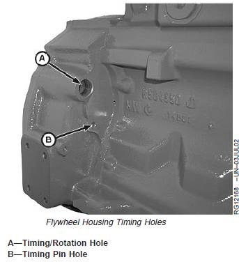
2. Remove plastic plugs or cover plate from enginetiming/rotation hole (A) and timing pin hole (B).
NOTE: Some engines are equipped with flywheelhousings which do not allow use of an engineflywheel rotation tool. These engines with straightnose crankshafts may be rotated from front noseof engine, using JDG966 Crankshaft Front/RearRotation Adapter.
3. Using JDE83 or JDE81-1 Flywheel Turning Tool, rotateengine flywheel in running direction (clockwise viewedfrom front) until No. 1 cylinder is at TDC compressionstroke. Insert JDG1571 or JDE81-4 Timing Pin inflywheel.
If No. 1 cylinder rocker arms are loose, the engine is at
No. 1 TDC compression.
If No. 1 cylinder rocker arms are not loose, rotateengine one full revolution (360°) to No. 1 TDCcompression.
4. With engine lock-pinned at TDC of No. 1 piston’scompression stroke, check valve clearance to followingspecifications. (Use sequence for 4-cylinder or
6-cylinder engines as outlined on next page.)
Specification
Intake Valve Clearance Checking(Rocker Arm-to-Bridge) (Engine
Cold)—Clearance ................................ 0.31—0.38 mm (0.012—0.015 in.)Exhaust Valve ClearanceChecking (Rocker Arm-to-Bridge)
(Engine Cold)—Clearance................... 0.41—0.48 mm (0.016—0.019 in.)
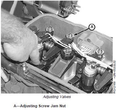
5. If valves need adjusting, use the appropriate valveclearance adjustment procedure on the next page andadjust to specifications below. Loosen the jam nut (A)on rocker arm adjusting screw. Turn adjusting screw until feeler gauge slips with a slight drag. Hold the adjusting screw from turning with screwdriver and tighten jam nut to specifications. Recheck clearance again after tightening jam nut. Readjust clearance as necessary.
Specification
Intake Valve ClearanceAdjustment (RockerArm-to-Bridge) (Engine Cold)—
Clearance ................................................................... 0.36 mm (0.014 in.)
Exhaust Valve Clearance
Adjustment (RockerArm-to-Bridge) (Engine Cold)—
Clearance ................................................................... 0.46 mm (0.018 in.)
Rocker Arm Adjusting Screw Jam
Nut—Torque .................................................................... 27 N•m (20 lb-ft)
6. Install rocker arm cover and crankcase ventilator tube.
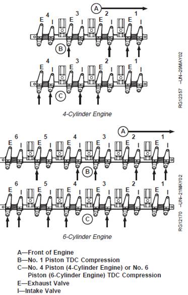
John Deere约翰迪尔强鹿柴油发动机4缸发动机的气门调整方法
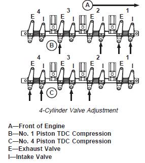
NOTE: Firing order is 1-3-4-2.
1. Using JDG1571 or JDE81-4 Timing Pin, lock No. 1piston at TDC compression stroke (B).
2. Adjust valve clearance on No. 1 and 3 exhaust valvesand No. 1 and 2 intake valves.
3. Turn crankshaft 360°. Lock No. 4 piston at TDCcompression stroke (C).
4. Adjust valve clearance on No. 2 and 4 exhaust valvesand No. 3 and 4 intake valves.
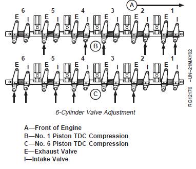
John Deere约翰迪尔强鹿柴油发动机6缸发动机的气门调整方法
6-Cylinder Engine:
NOTE: Firing order is 1-5-3-6-2-4.
1. Using JDG1571 or JDE81-4 Timing Pin, lock No. 1piston at TDC compression stroke (B).
2. Adjust valve clearance on No. 1, 3 and 5 exhaustvalves and No. 1, 2, and 4 intake valves.
3. Turn crankshaft 360°. Lock No. 6 piston at TDCcompression stroke (C).
4. Adjust valve clearance on No. 2, 4 and 6 exhaustvalves and No. 3, 5, and 6 intake valves.
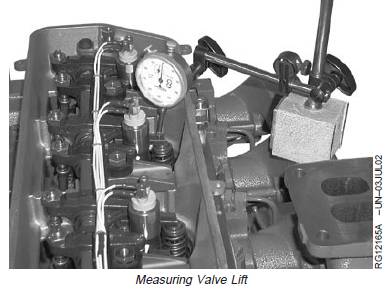
John Deere约翰迪尔强鹿柴油发动机气门行程的测量方法
IMPORTANT: For a more accurate measurement,measure valve lift at 0.00 mm (0.00 in.)rocker arm-to-valve tip clearance andwith engine COLD.
NOTE: Measuring valve lift provides an indication of wearon camshaft lobes and camshaft followers or pushrods.
1. Remove rocker arm cover.
2. Using JDE81-1 or JDE83 Flywheel Turning Tool andJDG1571 or JDE81-4 Timing Pin inserted in flywheel,lock No. 1 piston at TDC compression stroke.
3. Set rocker arm-to-valve tip clearance to 0.00 mm (0.00in.) for:
· No. 1 and 3 exhaust and No. 1 and 2 intake valveson 4-cylinder engines.
· No. 1, 3, and 5 exhaust and No. 1, 2, and 4 intakevalves on 6-cylinder engines.
4. Place dial indicator tip on top of valve bridge. Preloadindicator tip and set dial at 0.0 mm (0.0 in.).
5. Remove timing pin from flywheel and manually rotateengine one full revolution (360°) in running directionusing appropriate flywheel turning tool.
6. Observe dial indicator reading as valve is moved to fullopen. Record maximum reading and comparewithspecifications given below.
Specification
Intake Valves—Lift 9.03—9.43 mm(0.356—0.371 in.)
Wear Limit .................................................................. 8.70 mm (0.343 in.)Exhaust Valves—Lift 9.32—9.72 mm(0.367—0.383 in.)
Wear Limit .................................................................. 9.00 mm (0.354 in.)
7. Follow same procedure for all remaining valves andrecord readings.
If valve lift on all valves is within specifications, adjustvalve lash to specified clearance. (See CHECK ANDADJUST VALVE CLEARANCE earlier in this group.)If valve lift on one or more valves is not withinspecification, remove and inspect entire valve train andcamshaft.
8. Rotate engine one full revolution (360°). Lock engineat:
· TDC No. 4 compression stroke for 4-cylinderengines.
· TDC No. 6 compression stroke for 6-cylinderengines.
9. Set rocker arm-to-valve tip clearance to 0.0 mm (0.0in.) for:
· No. 2 and 4 exhaust and No. 3 and 4 intake valveson 4-cylinder engines.
· No. 2, 4, and 6 exhaust and No. 3, 5, and 6 intakevalves on 6-cylinder engines.
10. Repeat steps 4—7.
免费热线
400-100-8969 15088860848
400-100-8969 15088860848
机组销售
0574-26871589 15267810868
0574-26871589 15267810868
配件销售
0574-26886646 15706865167
0574-26886646 15706865167
维修热线
0574-26871569 18658287286
0574-26871569 18658287286
手机端

微信公众号