 English
 Espaol
 Franais
 阿拉伯
阿拉伯 中文(简)
中文(简) Deutsch
 Italiano
 Português
 日本
日本 韩国
韩国 български
 hrvatski
 esky
esky Dansk
Dansk Nederlands
 suomi
suomi Ελληνικ
 印度
印度 norsk
norsk Polski
 Roman
Roman русский
 Svenska
 John Deere约翰迪尔强鹿柴油机活塞和连杆的拆装技术手册,John Deere约翰迪尔强鹿柴油机活塞和连杆的拆装技术手册技术支持,John Deere约翰迪尔强鹿柴油机活塞和连杆的拆装技术手册费用,John Deere约翰迪尔强鹿柴油机活塞和连杆的拆装技术手册服务中心,John Deere约翰迪尔强鹿柴油机活塞和连杆的拆装技术手册价格规格资料查询,John Deere约翰迪尔强鹿柴油机活塞和连杆的拆装技术手册哪里有,John Deere约翰迪尔强鹿柴油机活塞和连杆的拆装技术手册多少钱,John Deere约翰迪尔强鹿柴油机活塞和连杆的拆装技术手册附近联系电话,宁波日昕动力科技有限公司

John Deere约翰迪尔强鹿柴油机活塞和连杆的拆装技术手册
详细描述
John Deere约翰迪尔强鹿柴油机活塞和连杆的拆装技术手册
Remove Pistons and Connecting Rods
If engine is to be removed from the machine, see yourmachine technical manual.
CAUTION: Do not drain engine coolant until itcools below operating temperature. Then slowlyloosen block drain valve to relieve any
pressure.
1. Drain coolant and engine oil.
NOTE: If engine is to be completely disassembled, seeENGINE DISASSEMBLY SEQUENCE in Group010.
2. Remove cylinder head. (See REMOVE CYLINDERHEAD in Group 020 for two valve head or REMOVECYLINDER HEAD in Group 21 for four valve head.)
3. Remove camshaft followers and keep in order forreassembly in same position.
4. Clean all foreign material from cylinder block top deck.
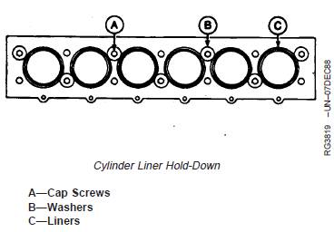
IMPORTANT: Cap screws and washers must betightened to the correct specification toachieve an accurate reading whenchecking liner standout (height aboveblock), as detailed later in this group.
5. Use short cap screws (A) and 3 mm (1/8 in.) thickwashers (B) to bolt down cylinder liners (C). Fasteneach liner in two locations. Tighten cap screws to 68
N•m (50 lb-ft).
NOTE: Do not rotate crankshaft with cylinder headremoved unless liners are fastened down.
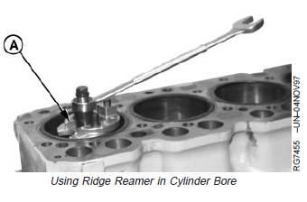
NOTE: Always follow manufacturer’s directions providedwith ridge reamer.
6. Remove carbon from liner bore with a scraper or ridgereamer (A). Use compressed air to remove loosematerial from cylinders.
7. Remove oil pan, oil pump, and pick-up tube. (SeeREMOVE, INSPECT AND INSTALL OIL PUMPPICK-UP TUBE ASSEMBLY in Group 060.) (SeeREMOVE ENGINE OIL PUMP in Group 060.)
8. Mark rods, pistons, and caps to ensure correctassembly in same location.
IMPORTANT: Keep inserts with their respective capsfor rod and main bearings.
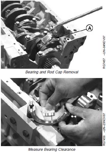
9. Remove all rod caps (A) with bearings.
10. Measure rod bearing-to-journal oil clearance withPLASTIGAGEâ before removing piston and rodassembly. Record measurements. (See INSPECTAND MEASURE CONNECTING ROD BEARINGS,later in this group.)
NOTE: Use PLASTIGAGEâ as directed by themanufacturer. PLASTIGAGEâ will determinebearing-to-journal oil clearance, but will notindicate the condition of either surface.
A—Rod Caps
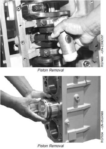
IMPORTANT: Hold onto piston to prevent piston fromdropping. Piston will drop once pistonrings have cleared cylinder liner.If liners are to be reused, be extremelycareful not to let connecting rod hitliner bore when removing piston androd assembly.
11. Gently tap piston through top of cylinder block fromthe bottom.
12. Remove pistons and rods from engine.
13. If piston rings are to be reused, measure piston ringend gap and compare to the following specifications:Piston Rings—4045DF, TF150 and 6068DF, TF150 Engines —Specification
No. 1 Compression—End Gap ........... 0.33—0.58 mm (0.013—0.023 in.)
No. 2 Compression—End Gap ........... 1.24—1.49 mm (0.049—0.059 in.)
No. 3 Oil Control—End Gap ............... 0.30—0.56 mm (0.011—0.022 in.)
Piston Rings—4045TF250 and 6068TF250 Engines—Specification
No. 1 Compression—End Gap ........... 0.33—0.64 mm (0.013—0.025 in.)
No. 2 Compression—End Gap ........... 0.75—1.00 mm (0.030—0.039 in.)
No. 3 Oil Control—End Gap ............... 0.33—0.64 mm (0.013—0.025 in.)
Heavy Duty Piston Rings—Specification
No. 1 Compression—End Gap ........... 0.33—0.59 mm (0.013—0.023 in.)
No. 2 Compression—End Gap ........... 0.89—1.14 mm (0.035—0.049 in.)
No. 3 Oil Control—End Gap ............... 0.33—0.59 mm (0.013—0.023 in.)
14. Remove all main bearing caps with bearings. Removecrankshaft from engine.
免费热线
400-100-8969 15088860848
400-100-8969 15088860848
机组销售
0574-26871589 15267810868
0574-26871589 15267810868
配件销售
0574-26886646 15706865167
0574-26886646 15706865167
维修热线
0574-26871569 18658287286
0574-26871569 18658287286
手机端

微信公众号