 English
 Espaol
 Franais
 阿拉伯
阿拉伯 中文(简)
中文(简) Deutsch
 Italiano
 Português
 日本
日本 韩国
韩国 български
 hrvatski
 esky
esky Dansk
Dansk Nederlands
 suomi
suomi Ελληνικ
 印度
印度 norsk
norsk Polski
 Roman
Roman русский
 Svenska
 John Deere约翰迪尔强鹿柴油机曲轴端部间隙、曲轴后油封的拆卸检查与标准值参数 ,John Deere约翰迪尔强鹿柴油机曲轴端部间隙、曲轴后油封的拆卸检查与标准值参数 技术支持,John Deere约翰迪尔强鹿柴油机曲轴端部间隙、曲轴后油封的拆卸检查与标准值参数 费用,John Deere约翰迪尔强鹿柴油机曲轴端部间隙、曲轴后油封的拆卸检查与标准值参数 服务中心,John Deere约翰迪尔强鹿柴油机曲轴端部间隙、曲轴后油封的拆卸检查与标准值参数 价格规格资料查询,John Deere约翰迪尔强鹿柴油机曲轴端部间隙、曲轴后油封的拆卸检查与标准值参数 哪里有,John Deere约翰迪尔强鹿柴油机曲轴端部间隙、曲轴后油封的拆卸检查与标准值参数 多少钱,John Deere约翰迪尔强鹿柴油机曲轴端部间隙、曲轴后油封的拆卸检查与标准值参数 附近联系电话,宁波日昕动力科技有限公司

John Deere约翰迪尔强鹿柴油机曲轴端部间隙、曲轴后油封的拆卸检查与标准值参数
详细描述
John Deere约翰迪尔强鹿柴油机曲轴端部间隙、曲轴后油封的拆卸检查与标准值参数
Measure end play prior to removing crankshaft todetermine condition of thrust bearings.
1. Position dial indicator on contact face of flywheel, onfront crankshaft nose, on damper, or front pulleyassembly, if installed.
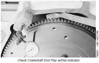
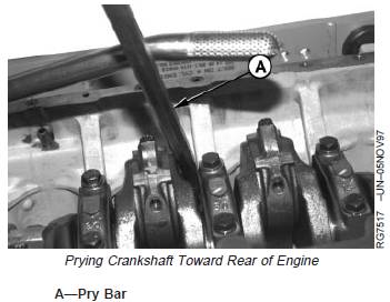
IMPORTANT: Do not apply too much pressure withpry bar (A), as this could damagebearings.
2. Using a pry bar, gently push crankshaft as far to rearof engine as possible.
3. Zero the dial indicator.
4. Gently pry the crankshaft as far forward as possible.Note indicator reading. If end play is not withinspecifications, install new thrust bearing.
SpecificationCrankshaft—End Play 0.029—0.357 mm (0.001—0.014in.)
曲轴后油封的拆卸方法
Use the following precautions for handling seal and wearsleeve assembly (A):
· Always install seal and wear sleeve assemblyimmediately after removal from plastic bag to avoidpossible dirt contamination.
· No lubrication of any kind is to contact seal wheninstalling. Use of a lubricant may result in prematureseal failure.
· Install oil seal/wear sleeve assembly with the open sideof seal and wear sleeve ID chamfer toward the engine.If seal is reversed, engine oil may be lost becausegrooves in oil seal lip would be incorrect with respect todirection of crankshaft rotation.
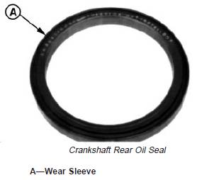
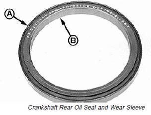
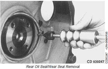
Remove Crankshaft Rear Oil Seal and WearSleeve
The crankshaft rear oil seal (A) and wear sleeve (B) arefabricated as a non-separable part. To remove the oilseal/wear sleeve assembly, the two following procedurescan be used depending on special tool availability.
A—Oil Seal
B—Wear Sleeve
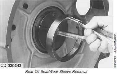
Remove Oil Seal/Wear Sleeve Using JDG698A
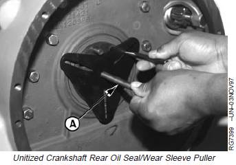
1. Adjust forcing screw (A) on JDG698A Seal and WearSleeve Remover and position screw so it centers toolon crankshaft flange.
2. Using the slots in JDG698A Remover as a template,mark three locations on seal casing where screwsshould be installed for removal purposes. Remove toolfrom crankshaft flange.
A—Forcing Screw
IMPORTANT: Holes must be drilled at outer edge ofseal case. Screws will pull seal againstwear ring, thereby removing bothpieces.
3. Drill a 3/16 in. hole through wear sleeve lip and sealcasing at the three marked locations.
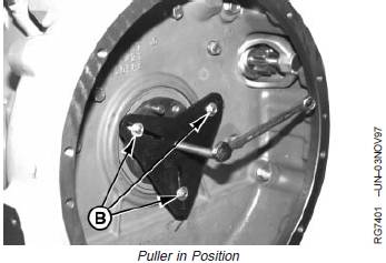
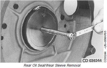
4. Position JDG698A Remover on end of crankshaft.
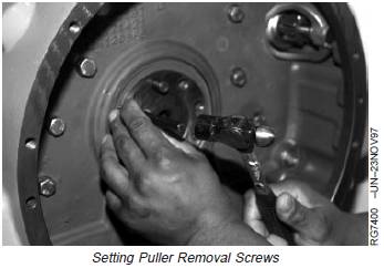
5. Install three 2-1/2 in. (approximate) sheet metal screwswith washers (B) into slots of removal tool and threadscrews into holes in seal casing. Evenly tighten screwsuntil plate is flush with rear face of crankshaft.
6. Tighten forcing screw (plate should pull evenly againstthe three screws) until seal and wear sleeve assemblyis removed from engine
B—Sheet Metal Screws
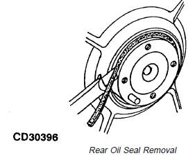
Remove Oil Seal/Wear Sleeve Using JDG645E
1. Place and center JDG645E Rear Crankshaft OilSeal/Wear Sleeve Puller cap screws and driver plateassembly onto crankshaft rear face. Then, using snapring pliers, set the thinner shoulder of ring tool betweensleeve flange and seal case.
2. Secure the assembly with a clamp, then graduallytighten the screw until wear sleeve is extracted.
3. Cut the rubber lip (now accessible) and remove it.
4. Using a punch and hammer, tap the seal case towardengine at any location until seal case pivots.
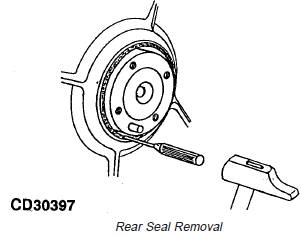
5. Using JDG22 Seal Remover, extract seal case.
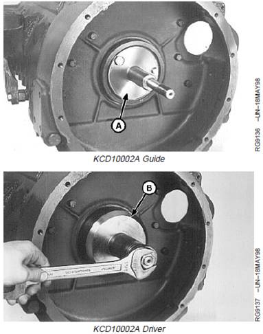
Install Rear Oil Seal/Wear Sleeve Using KCD10002A
NOTE: Due to a diameter change of the crankshaft bore,it may be necessary to suppress the pilot pin fromKCD10002. With this modification, KCD10002becomes KCD10002A
1. Position guide (A) from KCD10002A Rear OilSeal/Wear Sleeve Installer Set on crankshaft end withtwo cap screws finger tight.
2. Install new oil seal/wear sleeve assembly on guide withopen side of seal toward engine. Center the guide andtighten cap screws.
3. Slide driver (B) onto guide (A) and gradually tightenhex nut until driver bottoms on guide.
4. Remove seal driver and guide. Check that seal andwear sleeve assembly is properly positioned oncrankshaft flange and installed square in flywheelhousing bore.
A—Guide
B—Driver
免费热线
400-100-8969 15088860848
400-100-8969 15088860848
机组销售
0574-26871589 15267810868
0574-26871589 15267810868
配件销售
0574-26886646 15706865167
0574-26886646 15706865167
维修热线
0574-26871569 18658287286
0574-26871569 18658287286
手机端

微信公众号