 English
 Espaol
 Franais
 阿拉伯
阿拉伯 中文(简)
中文(简) Deutsch
 Italiano
 Português
 日本
日本 韩国
韩国 български
 hrvatski
 esky
esky Dansk
Dansk Nederlands
 suomi
suomi Ελληνικ
 印度
印度 norsk
norsk Polski
 Roman
Roman русский
 Svenska
 强鹿柴油机曲轴主轴承瓦的拆卸方法与曲轴、曲轴瓦间隙的检测技术规范,强鹿柴油机曲轴主轴承瓦的拆卸方法与曲轴、曲轴瓦间隙的检测技术规范技术支持,强鹿柴油机曲轴主轴承瓦的拆卸方法与曲轴、曲轴瓦间隙的检测技术规范费用,强鹿柴油机曲轴主轴承瓦的拆卸方法与曲轴、曲轴瓦间隙的检测技术规范服务中心,强鹿柴油机曲轴主轴承瓦的拆卸方法与曲轴、曲轴瓦间隙的检测技术规范价格规格资料查询,强鹿柴油机曲轴主轴承瓦的拆卸方法与曲轴、曲轴瓦间隙的检测技术规范哪里有,强鹿柴油机曲轴主轴承瓦的拆卸方法与曲轴、曲轴瓦间隙的检测技术规范多少钱,强鹿柴油机曲轴主轴承瓦的拆卸方法与曲轴、曲轴瓦间隙的检测技术规范附近联系电话,宁波日昕动力科技有限公司

强鹿柴油机曲轴主轴承瓦的拆卸方法与曲轴、曲轴瓦间隙的检测技术规范
详细描述
John Deere约翰迪尔强鹿柴油机曲轴主轴承瓦的拆卸方法与曲轴、曲轴瓦间隙的检测技术规范
Remove Crankshaft Main Bearings
1. Drain oil from engine crankcase and remove oil pan.
2. Remove timing gear cover. (See REMOVE TIMINGGEAR COVER in Group 050.)
3. Remove cylinder block front plate. (See REMOVECYLINDER BLOCK FRONT PLATE in Group 050.)
4. Remove flywheel housing. (See REMOVE FLYWHEELHOUSING in this group.)
5. Remove connecting rods from crankshaft. (SeeREMOVE PISTONS AND CONNECTING RODS inGroup 030.)
IMPORTANT: Before removing main bearing caps,check for proper torque on all mainbearings.
NOTE: When crankshaft is to be removed, leave frontand rear main bearing caps installed until allconnecting rod caps have been removed.
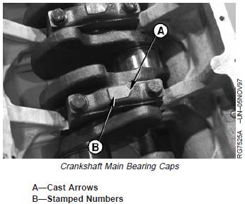
6. Check main bearing caps for arrows (A) cast in mainbearing cap, and numbers (B) stamped on cap and oilpan rail. Arrow points toward camshaft side of engine.If there are no numbers, stamp corresponding numberson cap and oil pan rail to ensure correct placement ofbearing caps during reassembly.
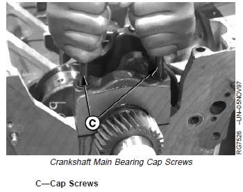
7. Remove main bearing caps by extending cap screws(C) and forcing heads of screws together. Wigglebearing cap back and forth while applying an upwardforce with cap screws until free from main bearing capsupport.
IMPORTANT: Keep matched bearings with theirrespective main bearing cap forcomparison with crankshaft journal(surface wear) from which removed.
8. Visually inspect condition of bearing inserts andcrankshaft main journals as bearing caps are removed.
曲轴瓦间隙的检查与标准值参数
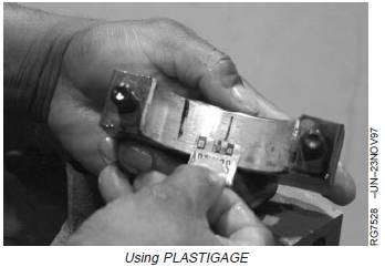
NOTE: The use of PLASTIGAGEâ will determine wear(crankshaft-to-bearing oil clearance) but will notdetermine condition of either bearing or journalsurface.
1. Place a strip of PLASTIGAGEâ in the center of themain bearing cap (with insert) about three-fourths ofthe width of the bearing or on crankshaft journal tomeasure oil clearance.
2. Use clean (SAE30) oil on PLASTIGAGEâ to preventsmearing.
3. Install cap and tighten cap screws to 135 N•m (100lb-ft).
4. Remove cap and compare width of PLASTIGAGEâwith scale provided on wrapper to determine clearance.
Specification
Crankshaft MainBearing-to-Journal—OilClearance 0.041—0.109 mm(0.0016—0.0043 in.)
John Deere约翰迪尔强鹿柴油机曲轴齿轮的拆卸和安装方法
NOTE: Remove crankshaft gear for replacement only; it isnot necessary to remove gear for crankshaftremoval.
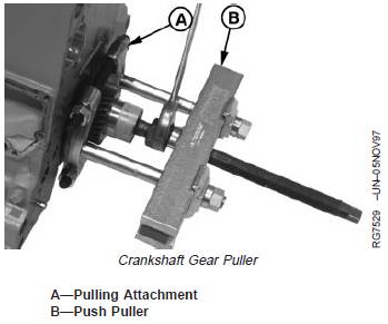
Remove Crankshaft Gear
1. Lock engine at No. 1 TDC compression.
2. Remove timing gear cover. (See REMOVE TIMINGGEAR COVER in Group 050.)
3. Remove oil pump. (See REMOVE ENGINE OIL PUMPin Group 060.)
4. Remove upper idler gear and lower idler gear andshaft. (See REMOVE LOWER AND UPPER IDLERSHAFTS in Group 050.)
5. Remove front plate. (See REMOVE CYLINDERBLOCK FRONT PLATE in Group 050.)
NOTE: Tapered nose crankshafts MUST have a threadprotector installed in nose before using puller toremove crankshaft gear.
6. Install No. 1123 (D01218AA) Pulling Attachment (A) orlarger onto crankshaft gear.
7. Install D01200AA Push Puller (B). Remove crankshaftgear.
Install Crankshaft GearIMPORTANT: If flame heat is used, be sure gear isheated uniformly around circumference.DO NOT OVERHEAT. SEE CAUTION.
Overheating may also destroy originalheat treatment of gear.CAUTION: Oil fumes or oil can ignite above
193°C (380°F). Use a thermometer and do notexceed 182°C (360°F). Do not allow a heatingelement to be in direct contact with the oil. Heatthe oil in a well-ventilated area. Plan a safehandling procedure to avoid burns.
1. Heat crankshaft gear to 148°C (300°F) using eitherheated oil or oven heat.
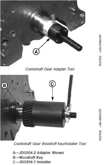
2. Install tool adapter (A) into nose of crankshaft untiladapter seats in bottom of crankshaft. Use JDG954-2Adapter for straight nose crankshafts or JDG954-7 fortapered nose crankshafts.
IMPORTANT: When installing gear, do not gouge ornick crankshaft flange.
NOTE: Chamfered side of gear should be installed towardengine.
3. Place gear on crankshaft flange. Be sure Woodruff key(B) on crankshaft is properly aligned with keyway ingear
4. Install JDG954-1 Installer (C) over adapter.
5. Tighten nut clockwise until gear firmly seats againstcrankshaft flange. Allow gear to cool before removinginstaller.
6. Refer to appropriate group to complete final assemblyof parts removed to access crankshaft gear.
Remove Crankshaft
1. Remove engine front plate. (See REMOVE CYLINDERBLOCK FRONT PLATE in Group 050.)
2. Remove flywheel housing and flywheel. (See REMOVEFLYWHEEL HOUSING earlier in this group.) (SeeREMOVE FLYWHEEL in this group.)
3. Remove main bearing caps and connecting rod caps,as described earlier in this group.
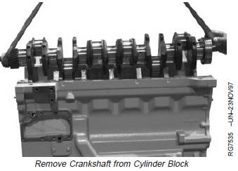
CAUTION: Crankshaft is very heavy. Plan aproper handling procedure to avoid injury.
4. Attach a lifting sling to crankshaft. Using proper liftingequipment, carefully raise crankshaft out of cylinderblock.
5. Clean crankshaft, especially oil passages, usingsolvent and compressed air.
6. Place crankshaft on clean V-blocks.
7. If main bearing inserts are to be replaced, removeinserts from cylinder block. Otherwise, leave bearinginserts in block until assembled ID has beenmeasured.
John Deere约翰迪尔强鹿柴油机曲轴的检查
NOTE: If vibration damper damage was discoveredduring teardown, it is recommended that thecrankshaft be magna-fluxed. This will verifywhether of not it has microscopic cracks orfissures. See INSPECT VIBRATION DAMPER
earlier in this group.
1. Thoroughly clean crankshaft. Clear restrictions from alloil passages.
IMPORTANT: Small cracks may not be visible to theeye. Use a method such as theFluorescent Magnetic Particle Method.This method magnetizes the crank,employing magnetic particles which arefluorescent and glow under “blacklight”. The crankshaft must bede-magnetized after inspection.
2. Inspect crankshaft for signs of load stress, cracks,scoring, or journal scratches. Replace crankshaft ifcracks are found.
3. Check each journal for evidence of excessiveoverheating or discoloration. If either condition exists,replace crankshaft since heat treatment has probablybeen destroyed.
4. Inspect front crankshaft gear for cracks, chipped teeth,
or excess wear. Replace gear as required.
5. Inspect the keyway for evidence of cracks or wear.Replace crankshaft as necessary.
6. Carefully inspect the rear hub of the crankshaft in thearea of the wear sleeve contact surface for evidence ofa rough or grooved condition. Any imperfections in thisarea will result in oil leakage. Slight ridges may becleaned up with emery cloth or crocus cloth.
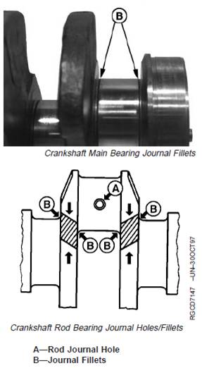
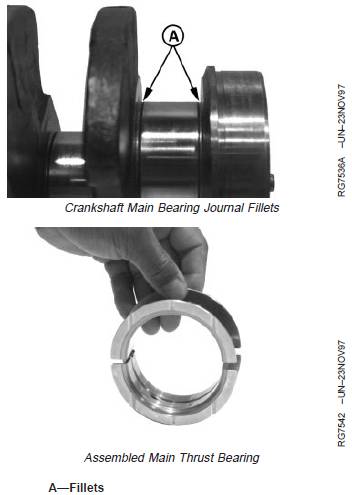
7. Carefully check the crankshaft for cracks in the area ofrod journal holes (A) and at journal fillets (B). Replacecrankshaft if any cracks are found.
曲轴轴颈和主轴的测量与标准值参数
1. With crankshaft removed from engine, assemble main bearing caps with bearing inserts. Be sure inserts are installed correctly.
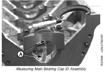
2. Tighten main bearing cap screws to 135 N•m (100lb-ft).
3. Measure and record main bearing assembled ID (A) at several points with an inside micrometer.
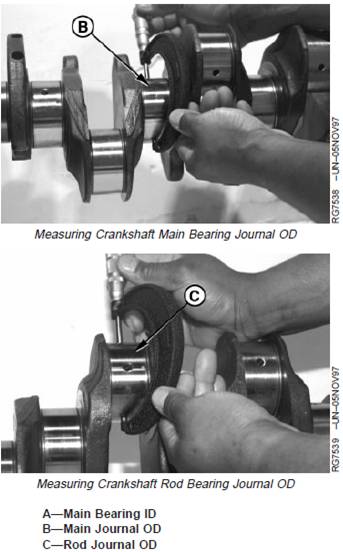
4. Measure and record crankshaft main journal OD (B) and rod journal OD (C) at several points around each journal.
NOTE: If an undersized crankshaft has been installed,measured dimensions will not meet specifications.However, bearing-to-journal oil clearance must be within specification. See CRANKSHAFT GRINDING GUIDELINES later in this group.
5. Compare measurements with specifications given below.
Specification
Crankshaft Main Bearing—ID 79.391—79.433 mm (3.1256—3.1273 in.)
Crankshaft Main Journal—OD 79.324—79.350 mm (3.1229—3.1240 in.)
Crankshaft Rod Journal—OD 77.800—77.826 mm (3.0629—3.0640 in.)
Crankshaft Main
Bearing-to-Journal—Oil Clearance 0.041—0.109 mm (0.0016—0.0043 in.)
Crankshaft Main or Rod
Journal—Maximum Taper ...................................... 0.010 mm (0.0004 in.)
Crankshaft Main or Rod
Journal—Maximum Out-of-Round.......................... 0.005 mm (0.0002 in.)
Replace or recondition crankshaft if it does not fall withinabove specifications.
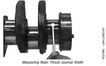
Measure Main Thrust Journal Width and Thrust Bearing Width
NOTE: If crankshaft has been previously reconditioned,thrust journal width may not be within abovespecifications. However, oil (side) clearance mustbe within specification.
1. Measure and record crankshaft main thrust journalwidth.If crankshaft thrust journal width is not within specifications, install a new crankshaft.
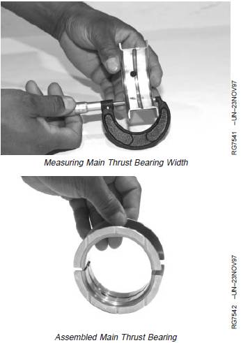
2. Measure and record width of main thrust bearing. Oil(side) clearance between thrust bearing and thrust journal must be within specifications.
Specification
Crankshaft Main Thrust Bearing Journal (New)—Width 38.952—39.028 mm (1.5335—1.5365 in.)
Crankshaft Main Thrust Bearing—Overall Width 38.79—38.87 mm(1.527—1.530 in.)
John Deere约翰迪尔强鹿柴油机磨削曲轴的方法规范与技术标准参数
Crankshaft Grinding Guidelines
IMPORTANT: Crankshaft grinding should be doneONLY by experienced personnel onequipment capable of maintainingcrankshaft size and finishspecifications. Undercut and rolledfillets (A) have taken the place ofground (tangential) fillets. DO NOTgrind within this undercut area whenundersize bearings are used.
Crankshafts have micro-finished journal surfaces.
IMPORTANT: If undersize bearings are installed,recheck bearing-to-journal clearance. Ifoil clearance is not withinspecifications, premature wear ofbearings and journals will result.
If the crankshaft is to be reground, use the followingrecommended guidelines:
1. Compare the crankshaft journal measurements takenduring inspection and determine the size which thejournals are to be reground.
2. Grind all main journals or all connecting rod journals tothe same required size.
IMPORTANT: Care must be taken to avoid localizedheating which often produces grindingcracks. Use coolant generously to coolthe crankshaft while grinding. DO NOTcrowd the grinding wheel into the work.Grind crankshaft with journals turningcounterclockwise, as viewed from thefront end of the crankshaft. Lap orpolish journals in opposite direction ofgrinding.
3. Polish or lap the ground surfaces to the specified finishto prevent excessive wear of the journals.
4. Stone the edge of all oil holes in the journal surfacessmooth to provide a radius of approximately 1.50 mm(0.060 in.).
5. When finished grinding, inspect the crankshaft by thefluorescent magnetic particle method, or other similarmethod to determine if cracks have originated due tothe grinding operation.
6. De-magnetize the crankshaft after inspection.
7. Thoroughly clean the crankshaft and oil passages withsolvent. Dry with compressed air.
Crankshaft Grinding Specifications
Bearing Size Crankshaft Main Journal OD Crankshaft Rod Journal OD
Standard ......................................................... 79.324—79.350 mm 77.800—77.826 mm
(3.1229—3.1240 in.) (3.0629—3.0640 in.)
0.25 mm (0.010 in.) Undersize ...................... 79.074—79.100 mm 77.550—77.576 mm
(3.1131—3.1141 in.) (3.0531—3.0541 in.)
Main and Connecting Rod Journal Surface Finish (AA) ..................... Lap 0.20 [micro ]m (8 AA)
Thrust Surface Finish (AA) .................................................................. Lap 0.40 [micro ]m (16 AA)
Thrust Bearing Journal Width .............................................................. 38.952—39.028 mm (1.5335—1.5365 in.)
Direction of Crankshaft Rotation (viewed from flywheel end):
Grinding ............................................................................................... Clockwise
Lapping ................................................................................................ Counterclockwise
Engine Stroke ...................................................................................... 127 mm (5.00 in.)
Main Journal Maximum Runout (Concentricity) Relative to No. 1 and
No.7 (6.8 L) or No. 1 and No. 5 (4.5 L) Journals ................................ 0.05 mm (0.0019 in.)
Main Journal Maximum Runout (Concentricity) Between Adjacent
Journals ................................................................................................. 0.025 mm (0.0009 in.)
免费热线
400-100-8969 15088860848
400-100-8969 15088860848
机组销售
0574-26871589 15267810868
0574-26871589 15267810868
配件销售
0574-26886646 15706865167
0574-26886646 15706865167
维修热线
0574-26871569 18658287286
0574-26871569 18658287286
手机端

微信公众号