 English
 Espaol
 Franais
 阿拉伯
阿拉伯 中文(简)
中文(简) Deutsch
 Italiano
 Português
 日本
日本 韩国
韩国 български
 hrvatski
 esky
esky Dansk
Dansk Nederlands
 suomi
suomi Ελληνικ
 印度
印度 norsk
norsk Polski
 Roman
Roman русский
 Svenska
 John Deere柴油机拆卸和安装凸轮轴衬套 ,John Deere柴油机拆卸和安装凸轮轴衬套 技术支持,John Deere柴油机拆卸和安装凸轮轴衬套 费用,John Deere柴油机拆卸和安装凸轮轴衬套 服务中心,John Deere柴油机拆卸和安装凸轮轴衬套 价格规格资料查询,John Deere柴油机拆卸和安装凸轮轴衬套 哪里有,John Deere柴油机拆卸和安装凸轮轴衬套 多少钱,John Deere柴油机拆卸和安装凸轮轴衬套 附近联系电话,宁波日昕动力科技有限公司

John Deere柴油机拆卸和安装凸轮轴衬套
详细描述
John Deere约翰迪尔强鹿柴油机拆卸和安装凸轮轴衬套
Remove and Install Camshaft Bushing withFront Plate Installed
NOTE: A camshaft bushing is installed in front (No. 1)camshaft bore only. The front plate has achamfered edge allowing camshaft bushingremoval and installation with the front plateinstalled.
Remove Camshaft Bushing
1. Set engine at No. 1 TDC compression.
2. On turbocharged engines, disconnect the turbochargeroil inlet line. (See DISCONNECT TURBOCHARGEROILINLET LINE in Group 010.)
3. Remove timing gear cover, as described earlier in thisgroup. (See REMOVE TIMING GEAR COVER in thisgroup.)
4. Remove rocker arm cover and rocker arm assembly.(See REMOVE CYLINDER HEAD in Group 020 or021.)
5. Remove push rods and identify location forreinstallation.
6. On engines with camshaft driven fuel supply pump,see REMOVE FUEL SUPPLY PUMP in Section 02,Group 090 of CTM207 (Mechanical Fuel Systems),REMOVE FUEL SUPPLY PUMP in Section 02, Group090 of CTM331 (Level 12 Electronic Fuel Systems withStanadyne DE10 Pump), or REMOVE MECHANICALFUEL TRANSFER PUMP in Section 02, Group 090 ofCTM220 (Level 11 Electronic Fuel Systems with DensoHigh Pressure Common Rail).
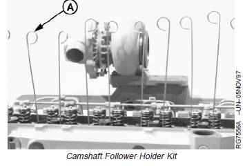
7. Revolve engine to an angle where camshaft followers fall away from camshaft or use D15001NU Magnetic Follower Holder Kit (A) to hold followers.
A—Magnetic Follower Holder Kit
8. Remove camshaft. (See REMOVE CAMSHAFT later inthis group.)
IMPORTANT: Engine MUST remain in a positionwhere camshaft followers rest againstcylinder head or are held in up positionby magnetic holders so that followersdo not fall into engine crankcase. Ifcamshaft followers fall into crankcase,cylinder head removal will be required.
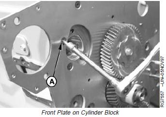
9. Remove countersunk TORXâ cap screw (A). InstallJDG739-7 (M8 x 1.25) tapered bottom leg (B) fromJDG739B Camshaft Bushing Service Kit into hole thathas chamfered screw and star washer.
IMPORTANT: Block must be replaced if camshaftbore is damaged. Be careful whenremoving or installing bushing.
10. Install JDG739-8 (M8 x 1.25) flat bottom legs anJDG739-3 Removing/Installing Plate (C) to cylinderblock so plate is parallel with front plate and centeredover camshaft bore. Tighten legs and hex nutssecurely.
IMPORTANT: Cylinder block bore may be damaged ifpuller is not properly piloted in bushing.Be sure puller is properly piloted beforepulling bushing.
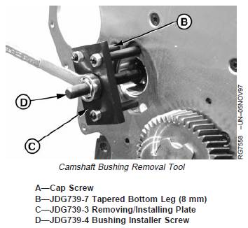
11. Insert JDG739-1 Bushing Remover into camshaftbore so puller pilots in bushing ID and JDG739-4Bushing Installer Screw (D) extends through plate.
12. Install thrust washer and hex nut. Tighten hex nutuntil bushing is free of block bore. Remove puller anddiscard bushing.
13. Clean and inspect bore in cylinder block. If bore isdamaged, replace cylinder block.
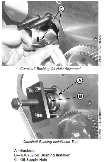
凸轮轴衬套安装
IMPORTANT: Bushings must be installed so oilsupply hole in bushing aligns with oildrilling in block bore.
1. Mark orientation of oil supply hole (C) on front face ofblock and on bushing to help with bushing alignmentduring installation.
2. Apply TY6333 High-Temperature Grease to ID and ODof new bushing (A), and to ID of bushing bore. Slidebushing onto JDG739-5B Bushing Installer (B) sonotched end of bushing will be toward front end ofengine when installed.
3. Thread JDG739-4 Bushing Installer Screw intoJDG739-3 Removing/Installing Plate. With bushingstarted, square in bore and oil hole aligned, tightenforcing screw until flange of bushing driver bottomsagainst face of block.
4. Remove bushing tool from cylinder block and check oilsupply hole for correct alignment. If holes are notaligned, remove and discard bushing. Install a newbushing.
拆卸和安装凸轮轴齿轮
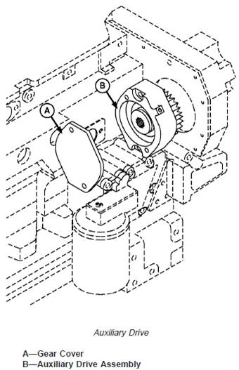
NOTE: Various auxiliary drive options are available;removal and installation of all options are similar.The auxiliary drive is integrated into the enginefront timing gear cover.
1. Remove lube line.
2. Remove auxiliary drive gear cover (A).
3. Clean and inspect cover for cracks or damage.
4. Remove auxiliary drive assembly (B).NOTE: Auxiliary drive assembly is repairable. Refer toCTM67, OEM Accessories, for additional serviceinformation.
5. Inspect for cracked housing, worn or damagedbearings, damaged gear or spline.
6. Repair or replace auxiliary drive assembly as needed.
7. Install gasket on auxiliary drive assembly and positionin the cylinder block plate. Install cap screws andtighten to specifications.
Specification
Auxiliary Drive-to-Cylinder Block
Plate—Torque.................................................................. 95 N•m (70 lb-ft)
8. Install cover and tighten cap screws or nuts tospecifications.
Specification
Auxiliary Drive Cover Plate—Torque ............................................................................. 55 N•m (41 lb-ft)
9. Install lube line.
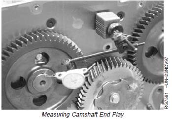
Measure Camshaft End Play
Measure camshaft end play.
Specification
Camshaft—End Play ........................... 0.08—0.23 mm (0.003—0.009 in.)
If end play is excessive, check thrust plate thickness withcamshaft removed. (See MEASURE CAMSHAFTTHRUST PLATE CLEARANCE AND THICKNESS, later inthis group.)
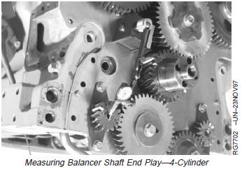
Measure Balancer Shaft End Play (IfEquipped—4-Cylinder Engines)
Measure balancer shaft end play.
Specification
Balancer Shaft—End Play................... 0.05—0.26 mm (0.002—0.010 in.)
If balancer shaft end play exceeds specifications, checkthrust plate thickness. (See INSPECT BALANCER SHAFTGEARS AND THRUST PLATES, later in this group.)
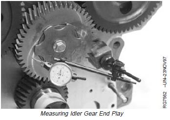
Measure Idler Gear End Play
Check end play of upper and lower idler gears.
Specification
Upper Idler Gear—End Play 0.070—0.170 mm(0.0027—0.0066 in.)
Lower Idler Gear—End Play 0.070—0.330 mm(0.0027—0.0129 in.)
If idler gear end play does not meet specifications, checkidler gear, idler shaft, and thrust washer for wear. (SeeMEASURE IDLER GEAR BUSHING AND SHAFT later inthis group.)
免费热线
400-100-8969 15088860848
400-100-8969 15088860848
机组销售
0574-26871589 15267810868
0574-26871589 15267810868
配件销售
0574-26886646 15706865167
0574-26886646 15706865167
维修热线
0574-26871569 18658287286
0574-26871569 18658287286
手机端

微信公众号