 English
 Espaol
 Franais
 阿拉伯
阿拉伯 中文(简)
中文(简) Deutsch
 Italiano
 Português
 日本
日本 韩国
韩国 български
 hrvatski
 esky
esky Dansk
Dansk Nederlands
 suomi
suomi Ελληνικ
 印度
印度 norsk
norsk Polski
 Roman
Roman русский
 Svenska
 约翰迪尔强鹿柴油机风扇张紧轮与风扇驱动组件拆卸和检查 ,约翰迪尔强鹿柴油机风扇张紧轮与风扇驱动组件拆卸和检查 技术支持,约翰迪尔强鹿柴油机风扇张紧轮与风扇驱动组件拆卸和检查 费用,约翰迪尔强鹿柴油机风扇张紧轮与风扇驱动组件拆卸和检查 服务中心,约翰迪尔强鹿柴油机风扇张紧轮与风扇驱动组件拆卸和检查 价格规格资料查询,约翰迪尔强鹿柴油机风扇张紧轮与风扇驱动组件拆卸和检查 哪里有,约翰迪尔强鹿柴油机风扇张紧轮与风扇驱动组件拆卸和检查 多少钱,约翰迪尔强鹿柴油机风扇张紧轮与风扇驱动组件拆卸和检查 附近联系电话,宁波日昕动力科技有限公司

约翰迪尔强鹿柴油机风扇张紧轮与风扇驱动组件拆卸和检查
详细描述
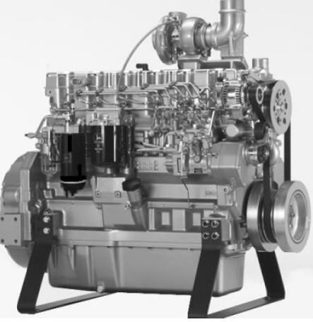
John Deere约翰迪尔强鹿柴油机风扇张紧轮与风扇驱动组件拆卸和检查
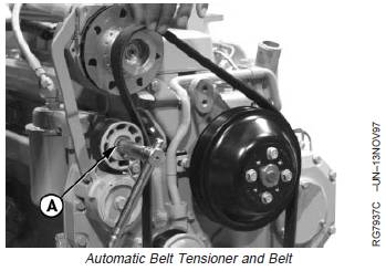
IMPORTANT: Belt tensioner cap screw (A) is left-hand
threaded.
1. Release tension on belts using a breaker bar and
socket.
2. Remove poly-vee belts from pulleys.
3. Remove belt tensioner.
A—Belt Tensioner Cap Screw
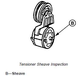
4. Inspect sheave (B).
IMPORTANT: If belt tensioner mounting plate was
removed, tighten cap screws to timing
gear cover first and then tighten cap
screws to engine.
5. Install belt tensioner and tighten cap screws to
specifications.
Specification
Belt Tensioner-to-Timing Cover
and Engine Cap Screws—Torque................................... 50 N•m (37 lb-ft)
Belt Tensioner Pulley Cap
Screw—Torque................................................................ 40 N•m (29 lb-ft)
6. Install poly-vee belts. Be sure that belt is correctly
seated in all pulley grooves.
Checking Belt Tensioner Spring Tension and
Belt Wear
Belt drive systems equipped with automatic (spring) belt
tensioners cannot be adjusted or repaired. The automatic
belt tensioner is designed to maintain proper belt tension
over the life of the belt. If tensioner spring tension is not
within specification, replace tensioner.
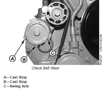
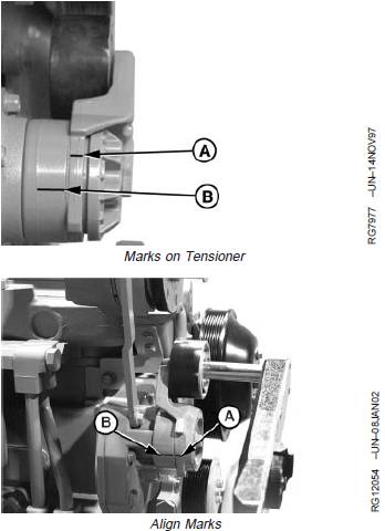
Checking Belt Wear
The belt tensioner is designed to operate within the limit
of arm movement provided by the cast stops (A and B)
when correct belt length and geometry are used.
1. Visually inspect cast stops (A and B) on belt tensioner
assembly.
2. If the tensioner stop on swing arm (C) is hitting the
fixed stop (B), check mounting brackets (alternator, belt
tensioner, etc.) and the belt length. Replace belt as
needed.
Checking Tensioner Spring Tension
A belt tension gauge will not give an accurate measure of
the belt tension when automatic spring tensioner is used.
Measure tensioner spring tension using a torque wrench
and procedure outlined below:
1. Release tension on belt using a breaker bar and
socket on tension arm. Remove belt from pulleys.
2. Release tension on tension arm and remove breaker
bar.
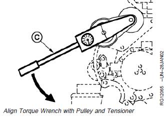
3. Put a mark (A) on swing arm of tensioner as shown.
4. Measure 21 mm (0.83 in.) from (A) and put a mark (B)
on tensioner mounting base.
5. Install torque wrench (C) so that it is aligned with
center of pulley and tensioner. Rotate the swing arm
with the torque wrench until marks (A and B) are
aligned.
6. Record torque wrench measurement and compare with
specification below. Replace tensioner assembly as
required.
Specification
Belt Tensioner—Spring Tension ...................... 18—22 N•m (13—16 lb-ft)
NOTE: Threads on belt tensioner roller cap screw are
LEFT-HAND threads.
A—Mark On Swing Arm
B—Mark On Tensioner Mounting Base
C—Torque Wrench
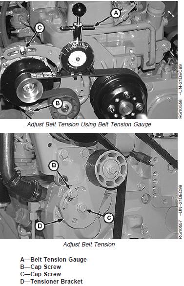
Manual Belt Tensioner Adjustment Using
Belt Tension Gauge
A—Belt Tension Gauge
B—Cap Screw
C—Cap Screw
D—Tensioner Bracket
NOTE: Two types of manual tensioners shown.
Inspect belts for cracks, fraying, or stretched-out areas.
Replace if necessary.
As a reference check, twist belt in the middle of a 254—
305 mm (10—12 in.) span with two fingers. A properly
tensioned belt will turn 75—85 degrees. If belt turns more,
it needs to be tightened. If belt turns less, it needs to be
loosened.
NOTE: If timing gear cover or alternator bracket interfere
with installation/centering of belt tension gauge
(A), install gauge with face toward engine.
1. Install JDG1341 Belt Tension Gauge (A) on belt,
halfway between pulleys as shown.
2. Loosen cap screws (B) and (C).
3. Slide alternator or tensioner bracket (D) in slot by hand
to remove all excess slack in belt.
IMPORTANT: Do not pry against alternator rear frame.
4. Stretch belt by prying outward on alternator front frame
or tensioner bracket. Observing tension gauge, stretch
the belt until specified tension is achieved.
8-Rib Poly-Vee Belt—Specification
New Belt—Tension................................. 470—650 N (105—145 lb-force)
Used Belt—Tension.................................. 400—580 N (90—130 lb-force)
5. Tighten cap screws (B) and (C).
NOTE: After ten minutes run-in, new belts are considered
used. Belt tension must then be rechecked per
used belt specifications.
6. Run engine for ten minutes and immediately re-check
belt tension per used belt specification above.
7. Reset belt tension as necessary.
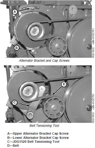
Manual Belt Tensioner Adjustment Using
Belt Tension Tool (Alternate Method for
Engines without Auxiliary Drive.)
A—Upper Alternator Bracket Cap Screw
B—Lower Alternator Bracket Cap Screw
C—JDG1520 Belt Tensioning Tool
D—Belt
NOTE: The JDG1520 Belt Tension Tool may not be
compatible with all alternators. In that case, use
the preceeding method for belt tensioning.
NOTE: Inspect belts for cracks, fraying, or stretched-out
areas. Replace if necessary.
As a reference check, twist belt in the middle of a
254—305 mm (10—12 in.) span with two fingers.
A properly tensioned belt will turn 75—85
degrees. If belt turns more, it needs to be
tightened. If belt turns less, it needs to be
loosened.
1. Loosen upper (A) and lower (B) alternator bracket cap
screws. Lower cap screw must remain tight enough to
prevent excessive alternator play but allow alternator to
pivot by hand.
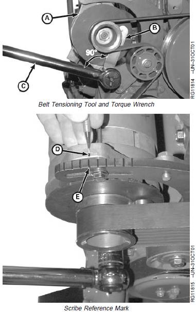
2. Insert JDG1520 Belt Tensioning Tool (C) behind belt
(D) and over lower alternator mounting screw.
3. Place torque wrench (C) on belt tensioning tool (B) at
90° to tool. Pivot alternator (A) until desired torque is
achieved according to specification using the following
table.
8-Rib Poly-Vee Belt—Specification
New Belt—Tension................................. 470—650 N (105—145 lb-force)
Used Belt—Tension.................................. 400—580 N (90—130 lb-force)
JDG1520 Belt Tensioning Tool Torque Table
Desired Belt Tension Applied Torque
N (lb-force) N •m (lb-ft)
445 (100) 108 (80)
489 (110) 115 (85)
534 (120) 122 (90)
623 (140) 135 (100)
4. While holding tension with torque wrench, scribe a
reference mark (D) on alternator in line with notch (E)
on upper alternator bracket.
5. Continue to hold tension with torque wrench and
tighten upper alternator bracket cap screw.
6. Check position of reference mark to see if alternator
moved while tightening. If alternator moved, loosen
upper alternator bracket cap screw and repeat the
tension adjustment procedure.
7. Remove belt tension tool and tighten lower alternator
bracket cap screw.
A—Alternator
B—Belt Tensioning Tool
C—Torque Wrench
D—Reference Mark
E—Alternator Upper Bracket Notch
Inspect and Install Fan Assembly
Several fan drive ratios are available, allowing a closer
matching of fan speed to application.
1. Inspect fan blades for bent or damaged condition. Bent
blades reduce cooling system efficiency and throw the
fan out of balance. Replace fan if blades are bent or
damaged.
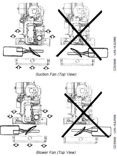
NOTE: Engines may be equipped with either suction-type
fan or a blower-type fan, depending on
application. Take care not to install fan incorrectly.
Refer to illustrations to identify fan type and
corresponding installation.
2. Install fan on pulley or pulley hub.
Install blower-type fan with concave side of blade
toward radiator.
Install suction-type fan with concave side of blade
toward engine.
Tighten cap screws (with lock washers) to
specifications.
Specification
Fan-to-Pulley Hub M8 Cap
Screws—Torque.............................................................. 35 N•m (26 lb-ft)
Fan-to-Pulley Hub M10 Cap
Screws—Torque.............................................................. 70 N•m (52 lb-ft)
John Deere约翰迪尔强鹿柴油机风扇驱动组件拆卸和检查
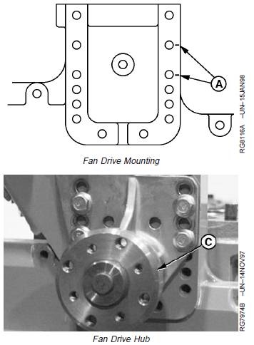
Remove and Inspect Fan Drive Assembly
Fan assemblies can be mounted in several positions to
accommodate different application and engine cooling
requirements.
1. Remove fan.
2. Release tension on belt and remove poly-vee belt from
pulleys.
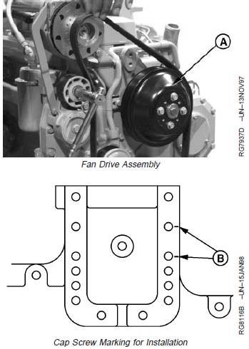
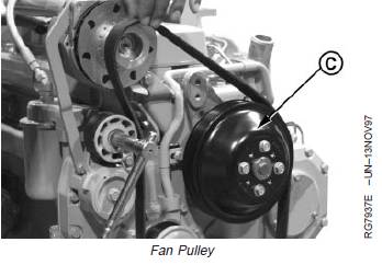
3. Remove fan pulley (A).
4. Inspect pulley and grooves
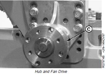
5. Check run-out of fan hub (C) using a dial indicator on
outer face of hub. If run-out exceeds specification,
replace fan drive assembly.
Specification
Fan Drive Hub—Radial Runout.............................. 0.038 mm (0.0015 in.)
NOTE: Cap screw position (B) is used as an example
only. Position of fan drive varies by application.
6. Mark cap screw positions (B) on timing gear cover
before removal to ensure that fan pulley is installed in
same position as removed. This will ensure proper belt
tension is achieved.
7. Remove hub (C) and fan drive.
A—Fan Pulley
B—Fan Drive Cap Screw Position
C—Hub
Replace Bearings in Adjustable Fan Drive Assembly
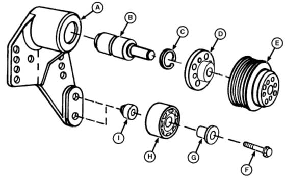
A—Bearing Housing D—Hub F—Cap Screw H—Idler Pulley
B—Bearing/Shaft E—Pulley G—Sleeve I—Spacer
C—Snap Ring
Disassemble Fan Drive Assembly
NOTE: Some parts in illustration above may not be
available separately for service. See parts
catalog for service parts/assemblies.
1. Support back side of fan hub (D) and press nose of
bearing/shaft (B) out of hub.
2. Remove snap ring (C) from front bore of bearing
housing (A).
3. Support front nose of bearing housing and press
bearing/shaft out of housing. Discard bearing.
4. Remove parts (F—I) if required.
5. Thoroughly clean and inspect fan hub, bearing
housing and idler pulley for cracks or any other
damage.
6. Measure parts and compare with specifications
given. Replace parts not within specifications.
Fan Drive (Option Codes 2301 and 2302)—Specification
Bearing Housing—ID 38.018—38.038 mm
(1.4968—1.4976 in.)
..........................................
Bearing—OD 38.087—38.100 mm
(1.4995—1.5000 in.)
.......................................................
Shaft—OD 18.948—18.961 mm
(0.7460—0.7465 in.)
...........................................................
Hub—ID 18.910—18.936 mm
(0.7445—0.7455 in.)
..............................................................
Fan Drive (Option Codes 2303, 2304, 2312, 2313, 2314, 2321 and
2341)—Specification
Bearing Housing—ID 47.573—47.599 mm
(1.8730—1.8740 in.)
..........................................
Bearing—OD 47.612—47.625 mm
(1.8745—1.8750 in.)
.......................................................
Shaft—OD 25.387—25.400 mm
(0.9995—1.0000 in.)
...........................................................
Hub—ID 25.337—25.353 mm
(0.9975—0.9985 in.)
Assemble Fan Drive Assembly
1. Support rear face of bearing housing and drive bearing
into housing by pressing on outer bearing shell until
bearing bottoms in housing bore.
2. Install internal snap ring into front groove of housing
bore.
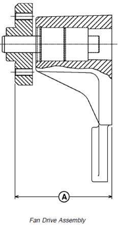
3. Support shaft through rear housing bore and press fan
hub onto shaft to dimension (A).
Fan Drive—Specification
Rear Housing Face-to-Hub Front
Face (Option Codes 2301 and
2303)—Distance 110.85—110.87 mm
(4.364—4.365 in.)
........................................................
Rear Housing Face-to-Hub Front
Face (Option Codes 2302, 2304,
2312, 2313 and 2314)—Distance 106.65—106.67 mm
(4.199—4.200 in.)
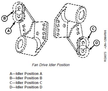
4. If idler pulley was removed, reinstall according to
following table:
Fan Pulley Fan Height Idler Position
168 mm (6.61 in.) 210 mm (8.27 in.) B
140 mm (5.51 in.) 210 mm (8.27 in.) A
203.2 mm (8.0 in.) 226 mm (8.9 in.) B
168 mm (6.61 in.) 226 mm (8.9 in.) B
140 mm (5.51 in.) 226 mm (8.9 in.) A
203.2 mm (8.0 in.) 258 mm (10.16 in) B
168 mm (6.61 in.) 258 mm (10.16 in) B
140 mm (5.51 in.) 258 mm (10.16 in) A
203.2 mm (8.0 in.) 290 mm (11.42 in.) B
168 mm (6.61 in.) 290 mm (11.42 in.) B
140 mm (5.51 in.) 290 mm (11.42 in.) A
203.2 mm (8.0 in.) 402 mm (15.83 in.) D
168 mm (6.61 in.) 402 mm (15.83 in.) C
140 mm (5.51 in.) 402 mm (15.83 in.) C
5. Torque idler retaining cap screw to specification.
Specification
Fan Drive Idler Cap Screw—
Torque ............................................................................. 50 N•m (37 lb-ft)
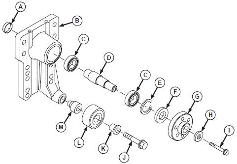
Replace Bearings in Heavy-Duty, Adjustable Fan Drive Assembly
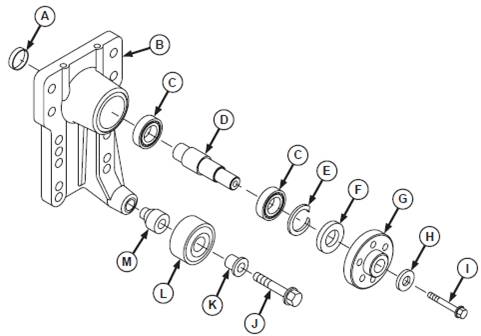
A—Plug E—Snap Ring H—Washer K—Sleeve
B—Bearing Housing F—Seal I—Cap Screw L—Idler Pulley
C—Bearing G—Hub J—Cap Screw M—Spacer
D—Shaft
Disassemble Fan Drive Assembly
NOTE: See parts catalog for service parts/assemblies.
1. Clamp fan hub (G) in a soft-jawed vise. Support fan
drive housing (so it does not fall to floor), and
remove cap screw (I) and washer (H) securing hub
to shaft (D). Remove fan hub from shaft.
2. Remove and discard grease seal (F) and snap ring
(E)
3. Remove plug (A) from rear bore of bearing housing.
4. Remove shaft with bearings (C) by lightly tapping
with a rubber mallet or brass hammer.
5. Remove bearings from shaft using a press and
discard bearings.
6. Thoroughly clean and inspect shaft and bearing
housing (B) for cracks or any other damage.
7. Measure parts and compare with specifications
given. Replace parts not within specifications.
Fan Drive (Option Codes 2309 and 2311)—Specification
Bearing Housing—ID 72.005—72.031 mm
(2.8348—2.8359 in.)
..........................................
Bearing—OD 71.987—72.013 mm
(2.8341—2.8351 in.)
.......................................................
Shaft—OD 30.218—30.234 mm
(1.1897—1.1903 in.)
...........................................................
Hub—ID 30.159—30.185 mm
(1.1874—1.1884 in.)
A—Plug E—Snap Ring H—Washer K—Sleeve
B—Bearing Housing F—Seal I—Cap Screw L—Idler Pulley
C—Bearing G—Hub J—Cap Screw M—Spacer
D—Shaft
Assemble Fan Drive Assembly
1. Pack inner and outer bearings (C) with TY6333 or
TY6347 High Temperature Grease. Apply clean
engine oil to bearing I.D. and shaft O.D.
IMPORTANT: Apply force to bearing inner race
only.
2. Support end of shaft (D) and install bearings
against shoulder.
3. Support bearing housing (B) on a firm flat surface
with bearing bore in the upward position.
4. Install bearing and shaft assembly into housing.
5. Determine proper snap ring (E) thickness needed to
obtain specified end play.
Specification
Fan Drive Shaft—Max. End
Play .................................................................... 0.25 mm (0.0098 in.)
6. Install snap ring in housing groove. Visually inspect
snap ring installation for proper seating in housing
groove.
7. Apply a thin coat of clean engine oil to O.D. of seal
(F) and to seal lips. Install seal in housing bore until
flush with housing.
8. Install plug (A) in rear of housing to specified height
above housing face.
Specification
Fan Drive Housing Plug—
Height 5.9—6.5 mm (0.2323—0.2559
in.)
..................................................
9. Apply clean engine oil to I.D. of fan hub (G) and
push onto shaft until it bottoms against shoulder.
10. Install washer (H) and cap screw (I). Tighten cap
screw to specifications.
Specification
Fan Hub-to-Fan Shaft—Torque.............................. 125 N•m (92 lb-ft)
11. Install idler pulley if removed. Torque idler
retaining cap screw to specification.
Specification
Fan Drive Idler Cap Screw—
Torque....................................................................... 50 N•m (37 lb-ft)
Install Fan Drive Assembly
IMPORTANT: Be sure adjustable fan drive assembly
is installed in correct position as
removed to ensure proper belt tension.
1. For engines using poly-vee belts: If reference marks
were not made on timing gear cover during removal of
fan drive assembly, use the following table to
determine proper fan height.
POLY-VEE BELT (MANUAL TENSIONER)
4.5 L Fan Belt Fan Height 6.8 L Fan Belt
Option Option
290 mm (11.42 in.) W/Idler Pulley (A)
240A, 240B, 240C, 24BK
240D
338 mm (13.31 in.) (A)
240E 240F
402 mm (15.83 in.) (A)
240G, 240H, 240J, 240K
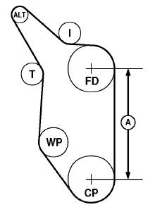
2. For engines using poly-rib-belts: If reference marks
were not made on timing gear cover during removal of
fan drive assembly, use figure to the right and following
table to determine proper fan height.
POLY-RIB BELT
4.5 L Fan Belt Fan Height 6.8 L Fan Belt
Option Option
210 mm (8.27 in.) W/Idler Pulley (A)
24AG, 24AH, 24AJ, 24AJ, 24AN
24AK, 24AL, 24AM
226 mm (8.9 in.) W/Idler Pulley (A)
2406, 2408, 2415, 2401, 2402, 2403,
2435, 2436, 2461, 2405, 2407, 2412,
240P, 240Q 2471, 2472, 2473,
2474, 240T, 240W
258 mm (10.16 in.) W/Idler Pulley (A)
24AR, 24AT 24BT
290 mm (11.42 in.) W/Idler Pulley (A)
2404, 2407, 2409, 2409, 2411, 2413,
2410, 2411, 2412, 2414, 2415, 2435,
2437, 2439, 2440, 2438, 2475, 2476,
2458, 2459, 2460, 240R, 240S, 240V
2462, 240U
338 mm (13.31 in.) (B)
2416, 2417, 2419, 2416, 2418, 2420,
2420, 2421, 2423, 2421, 2422, 2423,
2424, 2442, 2443, 2424, 2441, 2477,
2463, 2466, 2468 2478, 2479, 2482
402 mm (15.83 in.) (B)
2426, 2428, 2430, 2417, 2419, 2425,
2431, 2432, 2444, 2427, 2429, 2480
2445, 2464, 2465,
2469, 2470
402 mm (15.83 in.) W/Idler Pulley (C)
2434, 2446 2433
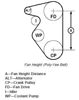
A—Fan Height Distance
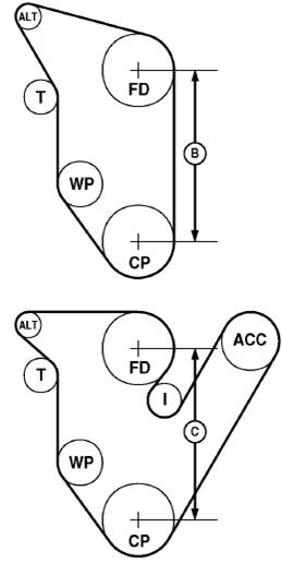
B—Fan Height Distance
C—Fan Height Distance
ALT—Alternator
CP—Crank Pulley
ACC—Air Conditioning Compressor
FD—Fan Drive
I—Idler
T—Tensioner
WP—Coolant Pump
NOTE: Cap screw position (A) is used as an example
only. Position of fan drive varies by application.
3. Install hub (C) with fan drive assembly, in positions (A)
marked during disassembly, and tighten cap screws to
specifications.
Specification
Fan Drive Assembly-to-Timing
Cover Cap Screws—Torque ........................................... 70 N•m (52 lb-ft)
A—Cap Screw Position
C—Fan Drive Hub
4. Install fan pulley (C) and tighten cap screws to
specifications.
Specification
Fan Pulley-to-Pulley Hub M8 Cap
Screws—Torque.............................................................. 35 N•m (26 lb-ft)
Fan Pulley-to-Pulley Hub M10
Cap Screws—Torque ...................................................... 70 N•m (52 lb-ft)
5. Install poly-vee belt. Be sure belt is correctly seated in
all pulley grooves.
C—Fan Pulley
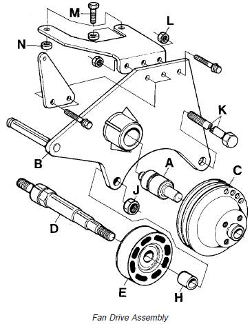
John Deere约翰迪尔强鹿柴油机拆卸和安装风扇驱动组件
1. Remove parts (A—E) and (H—N) as required.
2. Inspect and replace parts as necessary.
3. Press bearing shaft (A) into fan bracket (B) until
bearing face is flush with bracket end face.
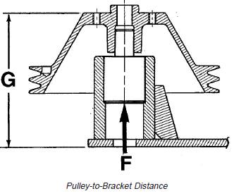
4. Place fan bracket under a press so that the thrust,
when pressing on pulley, is received only by the
bearing shaft end (F). Press pulley until distance (G) is
obtained.
Specification
Rear Housing Face-to-Hub Front
Face—Distance ........................................................ 123.5 mm (4.862 in.)
5. Install fan bracket on engine and tighten hardware to
specifications.
Fan Drive Assembly (2254 Combine)—Specification
Fan Idler Axle Shaft-to-Block
(D)—Torque................................................................. 340 N•m (251 lb-ft)
Fan Idler-to-Shaft Retaining Nut
(J)—Torque.................................................................. 225 N•m (166 lb-ft)
Fan Drive Bracket-to-Block Cap
Screw (K)—Torque...................................................... 340 N•m (251 lb-ft)
Fan Drive Bracket-to-Cylinder
Head Cap Screws (M)—Torque.................................. 140 N•m (103 lb-ft)
Upper Fan Drive
Bracket-to-Lower Bracket Cap
Screws/Nuts (L)—Torque............................................ 140 N•m (103 lb-ft)
A—Bearing Shaft
B—Fan Bracket
C—Pulley
D—Idler Axle Shaft
E—Idler
F—Bearing Shaft End
G—Distance for Pulley Installation
H—Spacer
J—Nut
K—Screw
L—Nut
M—Cap Screw
N—Spacer
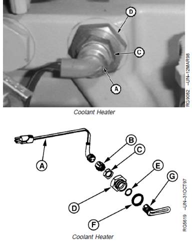
Remove and Install Coolant Heater (If
Equipped)
A—Cord
B—Dust Cover
C—Retaining Nut
D—Adapter
E—Gasket
F—O-Ring
G—Heater Element
CAUTION: To avoid shock or hazardous
operation, always use a three-wire heavy-duty
electrical cord equipped with three-wire
connectors. If a two-to-three contact adapter is
used at the wall receptacle, always connect
green wire to a good ground. Keep electrical
connectors clean to prevent arcing. Only plug
coolant heater into electrical power if heating
element is immersed in coolant. Sheath could
burst and result in personal injury.
1. Unplug heater from electrical power source.
2. Drain cooling system.
3. Disconnect cord (A) from heater assembly.
4. Loosen retaining nut (C) and remove adapter (D) and
heater element from block.
5. Inspect and replace parts as necessary.
NOTE: The heater element (G) cannot be repaired.
Replace if defective.
6. Install a new gasket (E). Apply JDT308 Soap Lubricant
to new O-ring (F) and install.
7. Install heater element through adapter (D) and install
nut (C) loosely.
8. Install heater into cylinder block with element pointing
to the rear.
9. Tighten adapter (D).
10. Turn element clockwise and then counterclockwise
until element contacts casting. Move element midway
between contact points.
11. Hold element with a wrench and tighten retaining nut
(C) to specifications.
Specification
Coolant Heater Lock Nut—Torque.................................. 35 N•m (26 lb-ft)
NOTE: If heater has been ordered as an attachment only,
it will include a dust cover (B). The cover is used
to protect the electrical connectors when cord
assembly (A) has been removed.
12. Install cord.
13. Service engine with coolant.
免费热线
400-100-8969 15088860848
400-100-8969 15088860848
机组销售
0574-26871589 15267810868
0574-26871589 15267810868
配件销售
0574-26886646 15706865167
0574-26886646 15706865167
维修热线
0574-26871569 18658287286
0574-26871569 18658287286
手机端

微信公众号