 English
 Espaol
 Franais
 阿拉伯
阿拉伯 中文(简)
中文(简) Deutsch
 Italiano
 Português
 日本
日本 韩国
韩国 български
 hrvatski
 esky
esky Dansk
Dansk Nederlands
 suomi
suomi Ελληνικ
 印度
印度 norsk
norsk Polski
 Roman
Roman русский
 Svenska
 帕金斯403C-15G,404C-22G1,404C-22G2,3.1524,1103A-33G,1103A-33TG1,1103A-33TG2,1004G,1004TG2,1104A-44TG1,1104A-44TG2,1006TG1A,1006TG2A,1006TAG,2006TAG,1306-E87T215,1306-E87TA300,2306-E14TAG1,2306-E14TAG2,2306-E16TAG1,2306-E16TAG2,2306-E14TAG3,2806-E16TAG1,2806-E16TAG2,3008TAG,3008TAG3,3008TAG4,3012TAG2B,3012TAG2A,3012TAG3A,4006TAG,4006-23TAG2A,4006-23TAG3A,4008TAG1A,4008TAG2A,4012TAG2,4012TAG2A,4016TAG2,4016TAG1A,4016TAG2A柴油发动机型号技术规格

帕金斯柴油发动机型号技术规格
详细描述
TableofContents
Specifications Section
EngineDesign .....................................................
FuelTransferPump .............................................
FuelFilterBase ....................................................
FuelFilter(Primary) ..............................................
FuelPrimingPump ..............................................
Electronic UnitInjector ..........................................
Electronic UnitInjectorMechanism .....................
Electronic UnitInjectorRockerArm......................
Electronic UnitInjectorWiring...............................
ValveMechanism .................................................
ValveMechanism Cover ......................................
4
4
5
5
6
6
7
7
8
9
9
Cylinder HeadValves ........................................... 10
Cylinder Head ...................................................... 11
Turbocharger ........................................................ 13
Exhaust Manifold ................................................. 13
Exhaust Elbow ..................................................... 14
Camshaft ............................................................. 14
EngineOilFilterBase .......................................... 15
EngineOilPump .................................................. 16
EngineOilPan ..................................................... 17
WaterLines........................................................... 17
WaterTemperatureRegulator Housing ................ 18
WaterTemperatureRegulator .............................. 18
WaterPump ......................................................... 19
Cylinder Block ...................................................... 19
Cylinder Liner ....................................................... 21
Crankshaft ........................................................... 21
Crankshaft Seals ................................................. 22
Vibration Damper ................................................. 22
Connecting RodBearingJournal ......................... 23
MainBearingJournal ............................................ 23
Connecting Rod ................................................... 24
PistonandRings .................................................. 24
PistonCooling Jet................................................. 25
Housing (Front)..................................................... 26
GearGroup(Front) ............................................... 27
Flywheel ............................................................... 28
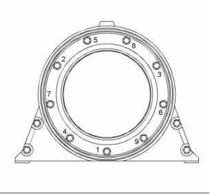
Flywheel Housing ................................................ 28
Flywheel Housing Cover ...................................... 28
BeltTightener ....................................................... 29
FanDrive ............................................................. 29
Alternator andRegulator ...................................... 30
Electric StartingMotor ......................................... 30
Coolant TemperatureSensor ............................... 31
FuelTemperatureSensor ..................................... 31
EngineOilPressure Sensor ................................. 32
Atmospheric PressureSensor .............................. 32
InletAirTemperatureSensor ................................ 32
InletManifold AirPressure Sensor ....................... 32
Speed/Timing Sensor .......................................... 33
Index Section
Index ..................................................................... 34
This document is printed from SPI². Not for RESALE
![]()
4
Specifications Section
KENR6905
SpecificationsSection
i02576024
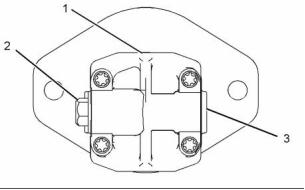
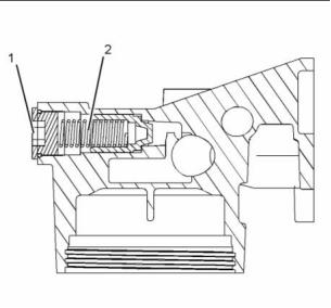
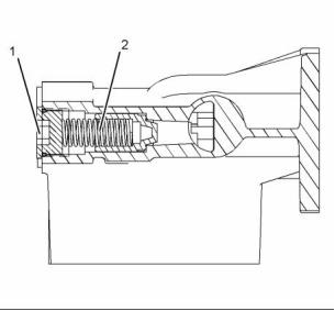
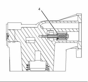
FuelTransferPump
i02796848
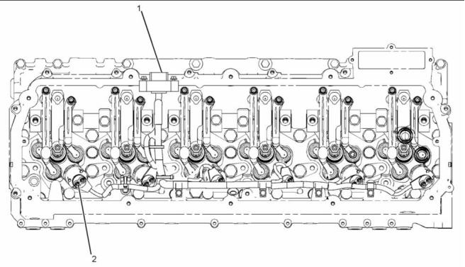
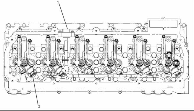
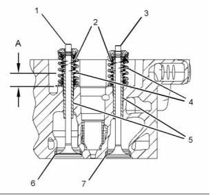
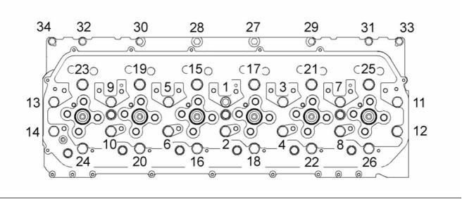
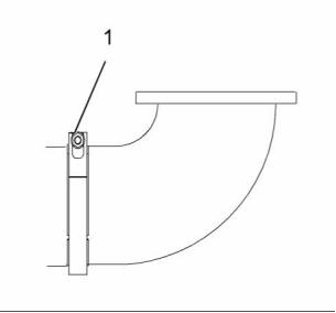
EngineDesign
g01320504
Illustration 2
g01193927
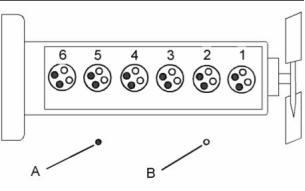
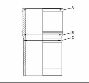
Illustration 1
Cylinder and valve location
(A) Inlet
(B) Exhaust
Bore ........................................... 130mm(5.12inch)
Stroke ........................................ 157mm(6.12inch)
Displacement .................................... 12.5L(763in)
3
Cylinder arrangement .................................... In-Line
Valvespercylinder.................................................. 4
Theadjustment fortheinletvalvelashisthefollowing
value. .............. 0.38±0.08mm(0.015±0.003inch)
The adjustment forthe exhaust valve lash isthe
following value. ................................ 0.64±0.08mm
(0.0252 ±0.0031 inch)
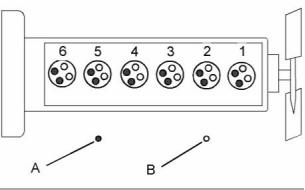
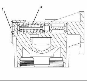
g01320507
Illustration 3
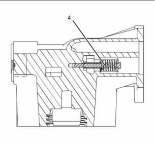
(1) Weep hole
(2) Pressure regulating valve
(3) Outlet port
Typeofcombustion........................... DirectInjection
Firingorder(injection sequence) ........ 1,5,3,6,2,4
Crankshaft rotation ....................... Counterclockwise
(4) Inlet port
Whenthefueltransfer pumpisusingdieselfuel,the
fueltransferpumphasthefollowing specifications:
1. Run the pump at 2940 rpm. The full bypass
Note: Thefront endoftheengine isopposite the
flywheel end.Theleftsideandtherightsideofthe
engine areviewed fromtheflywheel end.TheNo.1
cylinder isthefront cylinder.
pressureshouldbe716to786kPa(104to114psi).
2. Runthepump at840rpm.Theflowat550kPa
(80psi)mustbe3.0L/min(0.8USgpm).
3. Runthepumpat2940rpm.Theflowat650kPa
(94psi)mustbe4.5L/min(1.19USgpm).
This document is printed from SPI². Not for RESALE
![]()
![]()
KENR6905
5
Specifications Section
4. Runthepumpat120rpm.Keeptheinletopento
theatmosphere for10seconds. Block theinlet.
Thepump mustmaintain thevacuum of30kPa
(4.5psi)minimum in30seconds.
i02797008
FuelFilter(Primary)
5. Runthepumpat840rpm.Keeptheinletopento
theatmosphere for10seconds. Block theinlet.
Thepump must maintain thevacuum of45kPa
(6.5psi)minimum in30seconds.
Table1
Required Tools
Part Number
CV60889
6. Runthepumpat120rpmwithablocked inletfor
30seconds. Thepumpinletmusthaveasuction
liftof60.9kPa(18InHg)minimum.
Tool
Partdescription
A
POWERPART
Special
Lubricant
When thepump isviewed from thedrive end,the
rotation ofthepumpiscounterclockwise.
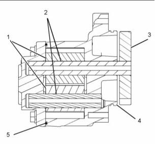
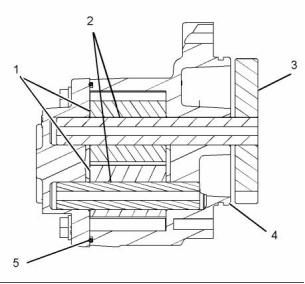
i02797015
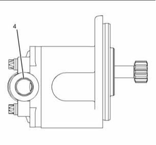
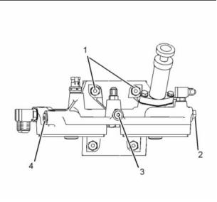
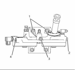
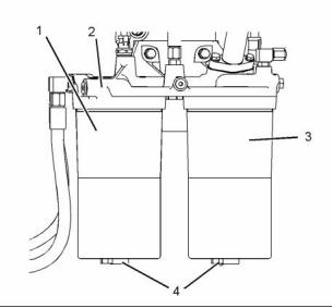
FuelFilterBase
g01287986
Illustration 5
Typical example
(1) Apply Tooling(A)tothethreads oftheprimary
fuelfilterhousing. Tightentheprimary fuelfilter
housing (1) to the fuel filter base (2) to the
following torque. ..........80±10N·m(59±7lbft)
(2) Fuel filter base
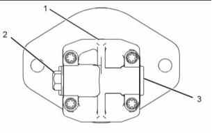
g01287856
Illustration 4
(3) ApplyTooling(A)tothethreads ofthesecondary
fuel filter housing. Tighten thesecondary fuel
filterhousing (3)tothefuelfilterbase(2)tothe
following torque. ..........80±10N·m(59±7lbft)
(1) Retaining setscrews ................. 47N·m(35lbft)
(2) Plug ........................................... 15N·m(11lbft)
(3) Plug ........................................... 15N·m(11lbft)
(4) Plug .......................................... 41N·m(30lbft)
(4) Drain Plugs
This document is printed from SPI². Not for RESALE
![]()

![]()
6
Specifications Section
KENR6905
i02797020
i02902879
FuelPrimingPump
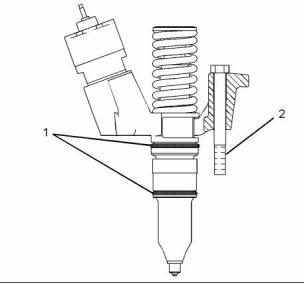
ElectronicUnitInjector
g01287938
g01091593
Illustration 6
Illustration 7
Typical example
(1) Lubricate the seals and the bore with clean
engine oil.
(1) Tightenthebolttothefollowing torque....25N·m
(220 lbin)
(2) Bolttorque ...................55±10N·m(40±7lbft)
(2) Priming pump
(3) Tightenthebolttothefollowing torque....12N·m
(105 lbin)
This document is printed from SPI². Not for RESALE
![]()
KENR6905
7
Specifications Section
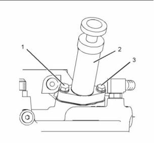
i02796843
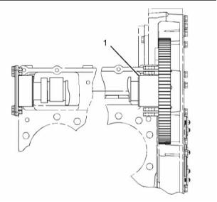
2. Turntheadjustment screwclockwise. Stopturning
theadjustment screwwhencontact ismadewith
theelectronic unitinjector (1).
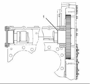
Electronic Unit Injector
Mechanism
3. Turntheadjustment screw clockwise.
Turn ........................... 180degrees (1/2ofaturn)
4. Holdtheadjustment screw.
Tighten the locknut (2) to the following
torque............................ 55±10N·m(41±7lbft)
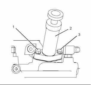
i02796844
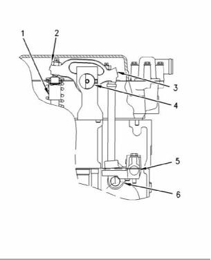
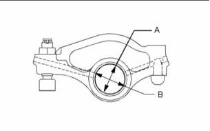
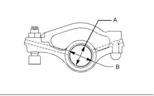
ElectronicUnitInjectorRocker
Arm
g01364153
Illustration 8
g01363845
Illustration 9
(1) Electronic unit injector
(2) Locknut
(A) Bearingborediameter......... 34.050±0.015mm
(1.3405 ±0.0006 inch)
(3) Electronic unit injector rocker arm
(4) Rocker arm shaft
(5) Lifter group shaft
(6) Electronic unit injector lifter
(B) Bore in the rocker arm for the
bearing................................. 37.000±0.020mm
(1.4567 ±0.0008 inch)
Procedure forsettingtheunitinjector assembly
1. Setnumber 1piston atTDCofthecompression
Note: The rocker arm bearing must not extend
stroke
beyond eitherfaceoftherocker arm.
2. Setunitinjectors oncylinder 3,5,and6.
3. Turnthecrankshaft 360degrees indirection of
engine rotation (number 6piston atTDCofthe
compression stroke).
4. Setunitinjectors oncylinder 1,2,and4.
The adjusting instructions fortheunit injector are
listed below.
1. Loosen thelocknut (2).
This document is printed from SPI². Not for RESALE
![]()
![]()
8
Specifications Section
KENR6905
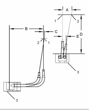
i02796846
ElectronicUnitInjectorWiring
g01072563
Illustration 10
(1) Wiring harness connectors
(2) Torqueforthecapnuts................ 2.5±0.25N·m
(22 ±2lbin)
This document is printed from SPI². Not for RESALE
![]()
KENR6905
9
Specifications Section
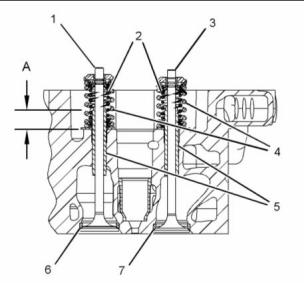
i02797205
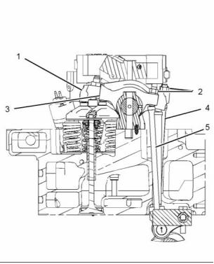
Valvelashsetting....................... 0.38±0.08mm
(0.015 ±0.003 inch)
Tightenjamnut(2)aftersettingthevalvelashto
thefollowing torque. .......................... 30±7N·m
(20 ±5lbft)
ValveMechanism
(4) Pushrod fortheexhaust valve
(5) Pushrod fortheInletvalve
i02797212
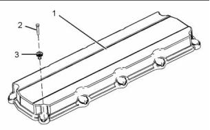
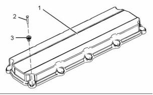
ValveMechanismCover
g01445055
Illustration 12
g01363806
Illustration 11
Procedure forsetting thevalvelash
1. Setnumber 1piston atTDCofthecompression
stroke
a. Setinletvalves oncylinder 1,2,and4
b. Setexhaust valvesoncylinders 1,3,and5
2. Turnthecrankshaft 360degrees indirection of
engine rotation (number 6piston atTDCofthe
compression stroke).
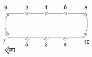
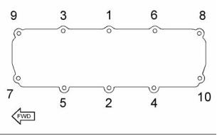
g01380900
Illustration 13
a. Setinletvalves oncylinder 3,5,and6
b. Setexhaust valvesoncylinders 2,4,and6
(1) Exhaust rocker arm
RefertoIllustration 13forthetightening sequence
ofthevalve cover bolts.
(1) Valvemechanism cover
(2) Bolts
Valvelashsetting ...................... 0.64±0.08mm
(0.025 ±0.003 inch)
Tightenthejamnut(2)aftersettingthevalvelash
tothefollowing torque. ...................... 30±7N·m
(20 ±5lb ft)
Torqueforbolts......................... 28N·m(21lbft)
(3) Isolators
(3) Inlet rocker arm
This document is printed from SPI². Not for RESALE
![]()
![]()
10
Specifications Section
KENR6905
i02796322
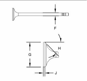
(B)Valvestemdiameter ........ 9.441±0.008mm
(0.3717 ±0.0003 inch)
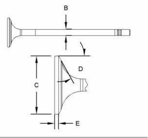
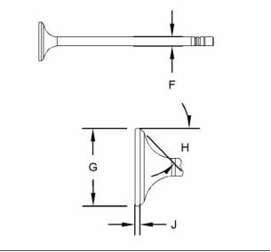
CylinderHeadValves
Minimum valvestemdiameter ............ 9.309mm
(0.3665 inch)
(C)Diameter ofvalvehead...... 44.50±0.13mm
(1.752 ±0.005 inch)
(D)Valvefaceangle ......... 60.75±0.25degrees
(E)Minimumvalvelipthickness ..3.50±0.20mm
(0.138 ±0.008 inch)
(2) Spring
Assembled length ........... 50.47mm(1.987inch)
Loadatassembled length ................. 160±13N
(36 ±3lb)
Minimum operating length .................. 34.92mm
(1.375 inch)
Loadatminimum operating length ....385±18N
(87 ±4lb)
Outsidediameter ............ 23.24mm(0.915inch)
Freelengthaftertest .......... 64.1mm(2.52inch)
g01352702
Illustration 14
g01352701
Illustration 16
Exhaust valve
(3) Exhaust valve
(F)Valvestemdiameter ........ 9.441±0.008mm
(0.3717 ±0.0003 inch)
Minimum valvestemdiameter ............ 9.309mm
(0.3665 inch)
g01352699
Illustration 15
Inlet valve
(G)Diameter ofvalvehead ..... 41.50±0.13mm
(1.634 ±0.005 inch)
Note: Apply engine oiltothevalve stems prior to
(H)Valvefaceangle ......... 45.75±0.25degrees
(J)Minimumvalvelipthickness ..3.50±0.20mm
(0.138 ±0.008 inch)
installation inthecylinder head.
(A) Height to the step in the valve
guide............... 22.0±0.5mm(0.87±0.02inch)
(4) Spring
Assembled length ........... 52.95mm(2.085inch)
(1) Inlet valve
This document is printed from SPI². Not for RESALE
![]()
![]()
KENR6905
11
Specifications Section
Loadatassembled length .................320±31N
(72 ±7lb)
Minimum operating length .................. 37.40mm
(1.472 inch)
Loadatminimum operating length ....860±34N
(195 ±7.6 lb)
Outside diameter ............ 34.00mm(1.339inch)
Freelengthaftertest .......... 62.7mm(2.47inch)
(5) Valveguide
Boreofinstalled valveguide.. 9.508±0.013mm
(0.3743 ±0.0005 inch)
Maximum recommended diameter ofthevalve
guidebore..................... 9.544mm(0.3757inch)
Note: Do not use acombination ofavalve and
a valve guide that has adifference of 0.13 mm
(0.005 inch) ormore.
(6) Inlet valve seat
Angleofvalveseat ........... 60.25±0.25degrees
Diameter ofvalveseat......... 45.525±0.013mm
(1.7923 ±0.0005 inch)
Bore in cylinder head for valve
seat.. 45.461±0.015mm(1.7898±0.0006inch)
(7) Exhaust valve seat
Angleofvalveseat ........... 44.75±0.25degrees
Diameter ofvalveseat......... 42.390±0.015mm
(1.6689 ±0.0006 inch)
Bore in cylinder head for valve
seat.. 42.320±0.015mm(1.6661±0.0006inch)
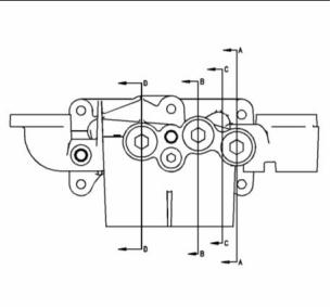
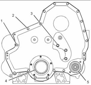
i02796321
CylinderHead
Table2
Required Tools
Tool
Part Number
Partdescription
A
CV60895
POWERPART
Special
Lubricant
ApplyTooling(A)totheboltthreads andbothsides
ofthewashers.
This document is printed from SPI². Not for RESALE
![]()

12
Specifications Section
KENR6905
g01400360
Illustration 17
1. Tightenbolt(1)through bolt(26)inanumerical
Rotate the bolts in the clockwise
direction. ..................... 120±5degrees (1/3turn)
sequence.
Tighten the bolts to the following
torque. .......................170±10N·m(125±7lbft)
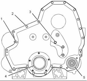
8. Tightenbolt(27)through bolt(33)inanumerical
sequence.
2. Tighten bolt (1) through bolt (26) again in a
Tighten the bolts to the following
torque................................................ 55±10N·m
(41 ±7lbft)
numerical sequence.
Tighten the bolts again to the following
torque. ............................................. 170±10N·m
(125 ±7lb ft)
3. Placeamarkonbolt(1)through bolt(26).Rotate
bolt(1)through bolt(26)inanumerical sequence.
Rotate the bolts in the clockwise
direction. ..................... 120±5degrees (1/3turn)
4. Loosen bolt (1) through bolt (26) until the
washers arelooseundertheboltheads.
5. Tightenbolt(1)through bolt(26)inanumerical
sequence.
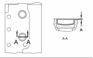
g01352102
Illustration 18
Tighten the bolts to the following
torque. ............................................. 170±10N·m
(125 ±7lb ft)
(A) The cup plugs are measured from the head
face to the top edge of the plug. Depth of
installation.................................. 1.25±0.25mm
(0.049 ±0.010 inch)
6. Tighten bolt (1) through bolt (26) again in a
numerical sequence.
Minimum permissible thickness of cylinder
head........................................................ 164.85mm
(6.4901 inch)
Tighten the bolts again to the following
torque. ............................................. 170±10N·m
(125 ±7lb ft)
Maximum permissible thickness of cylinder
head........................................................ 165.15mm
(6.502 inch)
7. Placeamarkonbolt(1)through bolt(26).Rotate
bolt(1)through bolt(26)inanumerical sequence.
This document is printed from SPI². Not for RESALE
![]()
![]()
KENR6905
13
Specifications Section
Note: The flatness of the cylinder
head should be within 0.15 mm
(0.006 inch). The flatness should also be a
maximumof0.05mm(0.002inch)forany150.00mm
(5.906 inch) span.
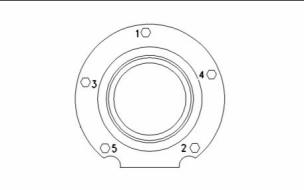
i02796858
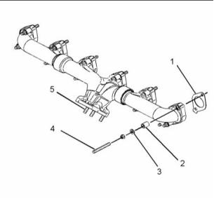
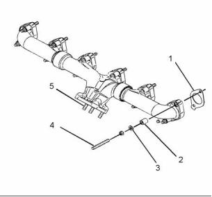
ExhaustManifold
i02797171
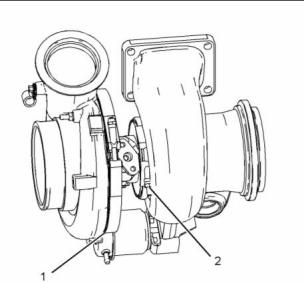
Turbocharger
g01332495
Illustration 20
Typical example ofanexhaust manifold with aflange with three
studs
(1) Exhaust manifold Gasket
(2) Spacer
(3) Washer
g01350326
Illustration 19
(4) Apply CV60889 Anti-Seize Compound tothe
studthreads. Tightenthestuds tothefollowing
torque. ........................... 35±5N·m(26±4lbft)
Typical example
(1) TorquefortheV-bandclamp .......13.5±1.0N·m
(120 ±9lbin)
(5) Apply CV60889 Anti-Seize Compound tothe
studthreads. Tightenthestuds tothefollowing
torque. ........................... 35±5N·m(26±4lbft)
(2) V-band clamp
1. TightentheV-band clamp.
Note:Theexhaust manifold gaskets havetabs.The
tabsshould point totheoilpan.
Torque................................... 18.1N·m(160lbin)
2. Loosen theV-band clamp.
Torque....................................... 5.6N·m(50lbin)
3. Again, tighten theV-band clamp.
Torque.................... 13.5±1.0N·m(120±9lbin)
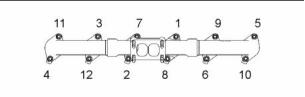
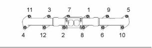
g01329313
Illustration 21
Tightening sequence (typical example)
Tightenthenutsinthenumerical sequence thatis
shown inIllustration 21.
This document is printed from SPI². Not for RESALE
![]()
![]()
14
Specifications Section
KENR6905
i02796856
i02796233
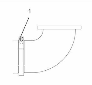
ExhaustElbow
Camshaft
g01290855
g01071831
Illustration 22
Illustration 23
Typical example
Typical example
(1) Tighten the nutforthe clamp tothe following
torque. ...................................... 14N·m(10lbft)
(1) Diameter of camshaft bearing
journal ... 77.850±0.025mm(3.0650 ±0.0010inch)
The lobe on the camshaft for the injector has
the most liftwhen the cam isatzero degrees of
rotation. ............................. 12.703mm(0.5001inch)
The lobe on the camshaft for the
injector has zero lift through the given
rotation. .......................... 74degrees to254degrees
Whentheinjector lobehasaliftheight of5.238mm
(0.2062 inch),thecamshaft shouldhaveanangleof
rotation. ...................................... 35±0.038degrees
The lobe on the camshaft for the inlet has the
most lift when the cam is at zero degrees of
rotation. ............................. 12.607mm(0.4963inch)
The lobe on the camshaft for the
inlet has zero lift through the given
rotation. .......................... 78degrees to284degrees
When theinlet lobe hasaliftheight of5.135 mm
(0.2022 inch),thecamshaft shouldhaveanangleof
rotation. .......................................... 32±0.2degrees
The lobe on the camshaft for the exhaust has
the most liftwhen the cam isatzero degrees of
rotation. ............................... 9.417mm(0.3707inch)
This document is printed from SPI². Not for RESALE
![]()
KENR6905
15
Specifications Section
The lobe on the camshaft for the
exhaust has zero lift through the given
rotation. .......................... 82degrees to279degrees
Whentheexhaust lobehasaliftheightof5.279mm
(0.2078 inch),thecamshaft should haveanangleof
rotation. .......................................... 32±0.2degrees
i02796849
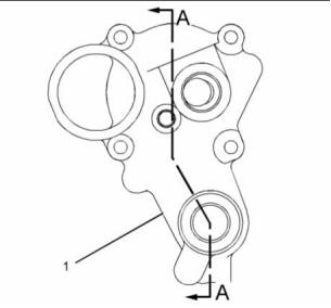
EngineOilFilterBase
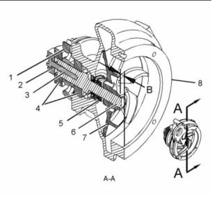
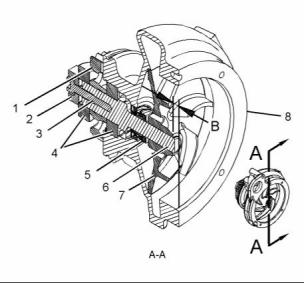
g01525668
Illustration 26
Section A-A
Oil cooler bypass
Pressure difference foropening theoilfilterbypass
valveandoilcoolerbypassvalve ........ 255±20kPa
(37 ±3psi)
(1) Torquefortheplugs ..100±15N·m(75±11lbft)
(2) Spring
Assembled length ........... 55.25mm(2.175inch)
Loadatassembled length ..................... 75±6N
(17.0 ±1.3 lb)
Freelengthaftertest .......... 93.7mm(3.69inch)
Outsidediameter ................ 20.6mm(0.81inch)
g01525662
Illustration 24
Right Side View
g01525673
g01525663
Illustration 27
Illustration 25
View D-D
Section B-B
Pump bypass valve
Oil filter bypass
This document is printed from SPI². Not for RESALE
![]()
![]()
![]()
![]()
![]()
16
Specifications Section
KENR6905
Fullopenpressure .............. 374.70kPa(54.346psi)
(3) Spring
i02796855
EngineOilPump
Assembled length ........... 96.52mm(3.800inch)
Loadatassembled length .......... 92.52N(21lb)
Freelengthaftertest .... 124.71mm(4.910inch)
Outsidediameter ............ 21.84mm(0.860inch)
g01330627
Illustration 29
g01525684
Typical example
Illustration 28
Section C-C
NOTICE
High pressure relief valve
Before operating the engine, the oil pump must be
lubricated with clean engine oil. The oil pump must
turn freely by hand. Damage to the drive gear and
internalpumpdamagecanoccuriftheoilpumpisnot
lubricated withclean engine oil.
Reliefpressure.................... 679.77kPa(98.594psi)
(4) Retainer Spring
Assembled length ........... 21.44mm(0.844inch)
Loadatassembled length ..............200±15.5N
(45.0 ±3.5 lb)
Freelengthaftertest ...... 30.96mm(1.219inch)
Outside diameter ............ 19.66mm(0.774inch)
Engine oilpump
Oiltype ................................................... SAE30
Oiltemperature ............................ 50°C(122°F)
Pumpspeed ........................................ 3000rpm
Oilpressure .............................. 359kPa(52psi)
Minimum oilflow ............ 185L/min(49USgpm)
(1) Pump gears
Inordertoinstallthepumpgears,heatthepump
gearstothefollowing temperature. ......... 316°C
(601 °F)
Lengthofnewgears ............ 50.000±0.025mm
(1.9685 ±0.0010 inch)
Depth of bores in oil pump body for the
gears....... 50.13±0.02mm(1.974±0.001inch)
(2) Oilpump shaftassembly
Diameter oftwoshafts......... 18.000±0.005mm
(0.7087 ±0.0002 inch)
This document is printed from SPI². Not for RESALE
![]()
![]()
![]()
KENR6905
17
Specifications Section
Bores in oil pump body for two
shafts ................................... 18.050±0.010mm
(0.7106 ±0.0004 inch)
i02797220
WaterLines
(3) Inordertoinstalltheoilpumpdrivegear,heatthe
geartothefollowing temperature. ........... 316°C
(601 °F)
(4) Seal groove
(5) O-ring seal
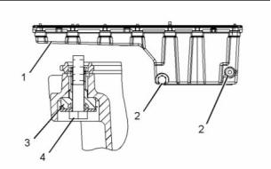
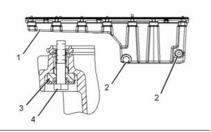
i02796850
EngineOilPan
g01530614
Illustration 31
Typical example
(1) Seal bores
Applyalightcoatofglycerintothesealbores.
g01098480
Illustration 30
Front sump
(1) Oil pan
(2) Torqueforplugs............................... 70±15N·m
(52±11lb ft)
(3) Rubber grommet
(4) Oil pan bolt
This document is printed from SPI². Not for RESALE
![]()
18
Specifications Section
KENR6905
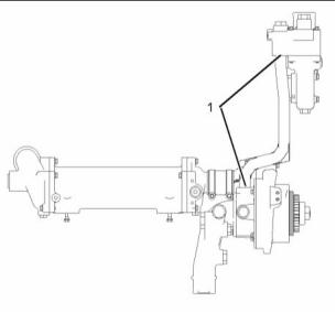
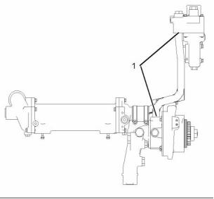
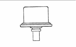
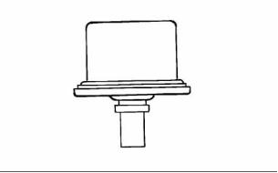
i03001200
i02797230
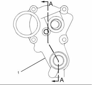
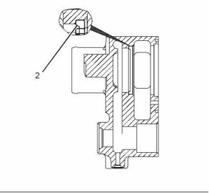
WaterTemperatureRegulator
WaterTemperatureRegulator
Housing
g00285471
Illustration 34
Typical example
Completely opentemperature ........... 98°C(208°F)
Minimum opening distance at 98 °C
(208°F)..................................... 10.4mm(0.41inch)
g01074249
Illustration 32
g01521205
Illustration 33
Section A-A
Note: Lightly lubricate thesealing lipoftheliptype
seal with glycerin.
The lip type seal (2) is installed in the water
temperature regulator housing (1).Thisisshown in
Illustration 33.
This document is printed from SPI². Not for RESALE
![]()
![]()
KENR6905
19
Specifications Section
i02797224
WaterPump
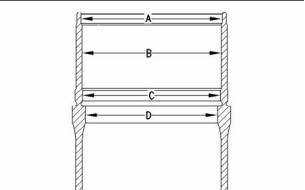
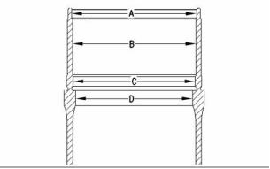
g00488509
Illustration 36
Borediameters inthecylinder blockforthecylinder
block liners:
(A)......... 151.50±0.03mm(5.965±0.001inch)
(B)......... 149.80±0.30mm(5.898±0.012inch)
(C)......... 148.00±0.03mm(5.827±0.001inch)
(D)......... 141.90±0.05mm(5.587±0.002inch)
g01329370
Illustration 35
(1) Gear
(2) Washer
(3) Bolt
(4) Ball bearings
(5) Seal group
(6) Water pump shaft
(7) Impeller
(8) Pump housing
The cup plug can be recessed to the following
distance. ................................. 1.25mm(0.049inch)
(B) Thedistance between thepumpflange andthe
impeller hub .............................. 8.40±0.25mm
(0.331 ±0.010 inch)
i02796319
CylinderBlock
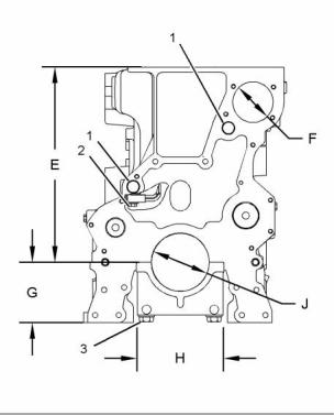
g01352212
Theflatness ofthetopcontactsurface ofthecylinder
block must bewithin 0.05mm(0.002 inch) forany
150mm(5.9inch)section ofthesurface.
Illustration 37
Front View
(2) Bolts forthe piston cooling jets
(E) Distance fromthecenterline ofthecrankshaft
bore to the top surface of the cylinder
block ........................... 387.00mm(15.236inch)
(F) Diameter of the camshaft
bores.................................... 85.000±0.015mm
(3.3464 ±0.0006 inch)
This document is printed from SPI². Not for RESALE
![]()
![]()
20
Specifications Section
KENR6905
(G) Distance from thecenterline ofthecrankshaft
to the bottom surface of the cylinder
block ................................. 120.0mm(4.72inch)
Width in cylinder block for the main bearing
cap ...... 178.000 ±0.023mm(7.0079±0.0009inch)
(H) Width of the main bearing
cap..................................... 178.000 ±0.020mm
(7.0079 ±0.0008 inch)
(J) Bore inthe cylinder block for theseven main
bearings .............................. 116.000±0.013mm
(4.5669 ±0.0005 inch)
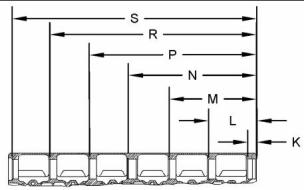
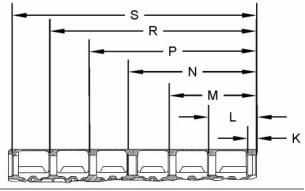
g01352291
(1) Apply6V-6640 Sealant totheboresofthecup
Illustration 38
plugs.
Thecamshaft bearings areinstalled intothecylinder
block atthevalues thatfollow.
(3) Main bearing capbolts
(K)................................... 36.50mm(1.437inch)
(L) ................................. 192.50mm(7.579inch)
(M) .............................. 348.50mm(13.720inch)
(N)............................... 504.50mm(19.862 inch)
(P)............................... 660.50mm(26.004inch)
(R)............................... 816.50mm(32.145 inch)
(S)............................... 972.50mm(38.287inch)
Use thefollowing procedure inorder toinstall the
main bearing capbolts:
1. Orient themainbearing cap correctly.The part
number onthemainbearing capmustfacetothe
right andtothefrontfaceoftheblock. Also, the
tabslotsthatareintheblockandthemainbearing
caps must beadjacent.
NOTICE
Camshaftbearingsmustbeinstalledintotheircorrect
position.Failuretodosowillresultinenginedamage.
Note: The main bearing caps are marked with
identification numbers 1through 7.Installthemain
bearing capsintothecorrect positions.
2. Lubricate themain bearing capbolts. UseSAE
30W oilormolybdenum grease tolubricate the
threads andthewasher face.
3. Tightenthemainbearing capbolts.
Tightenboltstothefollowing torque. ..50±5N·m
(37 ±4lb ft)
4. Putanalignment markoneachcapandbolt.
Rotate theboltsintheclockwise direction bythe
following angle. ............................ 90±5degrees
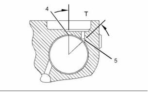
g01352353
Illustration 39
(4) Bearing joint
(5) Oil hole
(T) Bearing oilholeislocated atthefollowing angle
fromthevertical.Allthesevenbearings havethe
sameangle. ...................................... 45degrees
This document is printed from SPI². Not for RESALE
![]()
![]()
![]()
KENR6905
21
Specifications Section
i02796327
i02796281
CylinderLiner
Crankshaft
Table3
Required Tools
Tool
Part Number
Partdescription
A
21820221
POWERPART
Rubber Grease
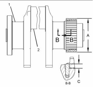
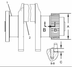
g01447590
Illustration 41
(1) Main bearing journals
(2) Connecting rodbearing journals
Thethrustplate should beusedonlyonthecenter
main bearing journals.
(A) Dimensions forcrankshaft gear
g00517737
Illustration 40
Average diameter after
Outside diameters ofthecylinder liner
assembly ................................ 136.20±0.11mm
(5.362 ±0.004 inch)
Note: Apply Tooling(A) tothecylinder linerseals
Maximum diameter afterassembly... 136.36mm
(5.368 inch)
prior toassembly.
Table4
(C) Heightfromtopofthedoweltothesurfaceofthe
crankshaft ......... 8.0±0.5mm(0.31±0.02inch)
Position A
Position B
Position C
151.42 ±0.05mm(5.961 ±0.002 inch)
147.90 ±0.03mm(5.823± 0.001 inch)
141.38 ±0.08mm(5.566 ±0.003 inch)
Note:Thegapbetween thecrankshaft gearandthe
crankshaft shouldnotexceed0.10mm(0.004inch).
InnerBore
Diameter
130.025±0.025mm(5.1191±0.0010inch)
This document is printed from SPI². Not for RESALE
![]()

![]()

22
Specifications Section
KENR6905
i02796303
CrankshaftSeals
g01331026
Illustration 43
Note: Usethealternating sequence thatisshown
whentightening thefrontandrearsealbolts.
i02797214
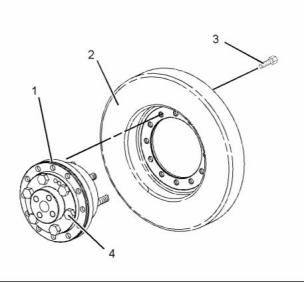
VibrationDamper
g01332511
Table5
Illustration 42
(1) Crankshaft seal
(3) Crankshaft
Required Tools
Part Number
Tool
Part Description
Note: Installthefrontcrankshaft seals andtherear
A
CV60889
Anti-Seize
Compound
crankshaft seals dry.
(2) O-ringseal ............ Lightlylubricate thesealwith
thelubricant thatisbeing sealed.
This document is printed from SPI². Not for RESALE
![]()
![]()
![]()

KENR6905
23
Specifications Section
i02797145
MainBearingJournal
Table7
Main Bearing Journal
Original sizejournal
108.000 ±0.020 mm
(4.2520 ±.0008 inch)
Undersize journal
0.510 mm(.0201 inch)
107.490 ± 0.020 mm
(4.2320 ±.0008 inch)
Undersize journal
0.760 mm(.0300 inch)
107.240 ±0.020 mm
(4.2220 ±.0008 inch)
Theclearance between anewbearing andanew
journalisthefollowing value....... 0.081to0.181mm
(.0032 to.0071 inch)
g01288983
Illustration 44
Table8
(1) Adapter
Main Bearing Bore
(2) Damper
Mainbearing bore(original
size)
116.000 ± 0.013 mm
(4.5669 ±.0005 inch)
(3) Tighten the bolts to the following
torque. .................................... 105N·m(77lbft)
Oversize bore inblock
0.510 mm(.0201 inch)
116.510 ± 0.013 mm
(4.5870 ±.0005 inch)
(4) ApplyTooling(A)totheboltsandtightenthebolts
tothefollowing torque. ......... 270N·m(200lbft)
i02796273
Connecting Rod Bearing
Journal
Table6
Connecting Rod Bearing Journal
Original sizejournal
89.000 ± 0.020 mm
(3.5039 ±.0008 inch)
Undersize journal
0.508 mm(.0200 inch)
88.492 ± 0.020 mm
(3.4839 ±.0008 inch)
Undersize journal
0.762 mm(.0300 inch)
87.238 ± 0.020 mm
(3.4346 ±.0008 inch)
The clearance between anew bearing andanew
journalisthefollowing value....... 0.062to0.132mm
(.0024 to.0052 inch)
This document is printed from SPI². Not for RESALE
![]()


24
Specifications Section
KENR6905
i02796261
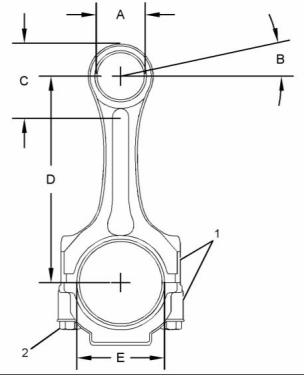
Bore inthe connecting rod for the piston pin
bearing................................. 57.810±0.013mm
(2.2759 ±0.0005 inch)
ConnectingRod
Bore in the bearing for the piston
pin... 53.205±0.008mm(2.0947 ±0.0003inch)
Diameter ofthepistonpin.... 53.155±0.005mm
(2.0927 ±0.0002 inch)
(B) Location ofthebearing jointfromthehorizontal
centerline ofthepinbore ......... 12.5±5degrees
Note: The connecting rodmust beheated forthe
installation ofthepiston pinbearing. Donotusea
torch.
(C) The connecting rod may be heated from
175 °C to260 °C (347 °F to 500 °F) for the
installation ofthepiston pinbearing. Maximum
distance forheating theconnecting rod... 88mm
(3.5 inch)
(D) Distance between the center of the
bearings ................................. 239mm(9.4inch)
(E) Bore intheconnecting rodforthe crankshaft
bearing................................. 93.800±0.013mm
(3.6929 ±0.0005 inch)
i02797157
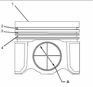
PistonandRings
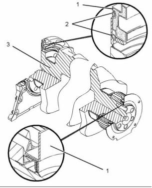
g01507769
Illustration 45
(1) Etchthecylinder number ontheconnecting rod
andthecapinthislocation. Marktheconnecting
rodandthecapwithanumber 1through 6.Mark
thenumbers onthesamesideoftheconnecting
rodasthebearing retainer notch.
Note:Installtheconnecting rodintheenginewiththe
partnumber totherearoftheengine.
Usethefollowingprocedure totightentheconnecting
rod bolts (2):
1. Tightentheconnecting rodboltsto130±7N·m
(95 ±5lbft).
2. Rotateeachconnecting rodboltsforanadditional
60±5degrees.
Note: Thoroughly lubricate the piston pin with
cleanengine oilpriortoassembly ofthepiston and
connecting rod.
g01324733
Illustration 46
(A) Dimensions forthepiston pin
(1) Thepistonissymmetrical withacentercrater.
This document is printed from SPI². Not for RESALE
![]()
![]()
![]()
KENR6905
25
Specifications Section
Lubricate theentirepistonto360°inzone(A)priorto
assembly intothecylinder block. Useclean engine
oil.
Thoroughly lubricate thepistonpinwithcleanengine
oilprior toassembly.
(2) Toppiston ringgroove
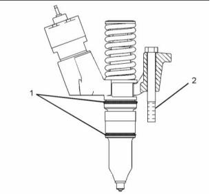
i02973664
PistonCoolingJet
Installthepistonringwiththesidemarked“UP-1”
toward thetopofthepiston.
The ends ofthepiston ring have aclearance
when the piston ring isinstalled inacylinder
linerwithaboreof130.000 mm(5.1181inch).
Clearance ..0.40±0.05mm(0.016±0.002inch)
Thetoppistonringhasanincrease inclearance
foreach 0.03mm(0.001 inch) increase inthe
cylinderlinerbore.Increase ................. 0.09mm
(0.004 inch)
(3) Intermediate piston ringgroove
Installthepistonringwiththesidemarked“UP-2”
toward thetopofthepiston.
Width ofgroove innewpiston forintermediate
pistonring .............................. 3.053±0.013mm
(0.1202 ±0.0005 inch)
Thickness of new intermediate piston
ring...........2.98±0.01mm(0.117±0.0004inch)
The ends ofthepiston ring have aclearance
when the piston ring isinstalled inacylinder
linerwithaboreof130.000 mm(5.1181inch).
Clearance ....... 0.8±0.1mm(0.03±0.004inch)
Theintermediate piston ringhasanincrease in
clearanceforeach0.03mm(0.001inch)increase
inthecylinder linerbore.Increase........ 0.09mm
(0.004 inch)
(4) Oilcontrol ringgroove
Theendsoftheoilcontrol pistonringshould be
adistance of180degrees fromtheringendgap
whentheoilcontrolpistonringisassembled. The
whitecolored portion ofthepiston ringmustbe
visible attheringendgap.
g01502131
Illustration 47
Thepiston cooling jets(3)mustbechecked forthe
location ofthestream ofoil.Insert adrillrodwitha
diameter of2.0mm(0.08inch) intotheorifice. This
drill rodsimulates thestream ofoilunder normal
operating pressure. Thedrillrodmustpassthrough
acircle withadiameter of10.0mm(0.40 inch) at
point(2).Placethedrillrodinthesecondorifice. , ; The
drillrodmustpassthrough acircle withadiameter
of10.0mm(0.40inch)atpoint (1).Thecircles are
located atdimension (D).
Widthofgrooveinnewpistonforoilcontrolpiston
ring......................................... 4.052±0.012mm
(0.1595 ±0.0005 inch)
Thickness of new oil control piston
ring.... 3.980±0.010mm(0.1567 ±0.0004inch)
The ends ofthepiston ring have aclearance
when the piston ring isinstalled inacylinder
linerwithaboreof130.000 mm(5.1181inch).
Clearance ..0.45±0.15mm(0.018±0.006inch)
The oil control piston ring has anincrease in
clearanceforeach0.03mm(0.001inch)increase
inthecylinder linerbore.Increase........ 0.09mm
(0.004 inch)
Usethefollowing dimensions inordertolocatepoint
(1)and point (2).
Dimension (A).......................... 47.10±0.25mm
(1.854 ±0.010 inch)
Dimension (B).......................... 55.30±0.25mm
(2.177 ±0.010 inch)
Afterthepistonringshavebeeninstalled, rotatethe
piston rings sothattheendgapsare120degrees
from each other.
Dimension (C)............................ 3.84±0.25mm
(0.151 ±0.010 inch)
Dimension (D)........................ 250.00±0.25mm
(9.842 ±0.010 inch)
(A) Pistonpinborediameter ......... 53.25±0.01mm
(2.0965 ±0.0004 inch)
Dimension (E)................... 4.50mm(0.177inch)
This document is printed from SPI². Not for RESALE
![]()
![]()
26
Specifications Section
KENR6905
i02797047
(5) Accessory driveassembly
Housing(Front)
g01190314
Illustration 48
g00952129
Illustration 49
Tightening sequence forthefront crankshaft seal
(1) Self-locking boltM8-1.25
(2) Seventeen boltsfastenthecovertothehousing.
Note:Bolt(1)isdifferentfromtheothercoverbolts.
(3) Nineboltsfastenthehousing totheblock.
(4) O-ring sealandcrankshaft frontseal
TheO-ringsealandthecrankshaft frontsealarepart
ofthefronthousing. Lubricate theO-ringseallightly.
Usethelubricant thatisbeingsealed.
This document is printed from SPI². Not for RESALE
![]()
![]()
KENR6905
27
Specifications Section
i02797043
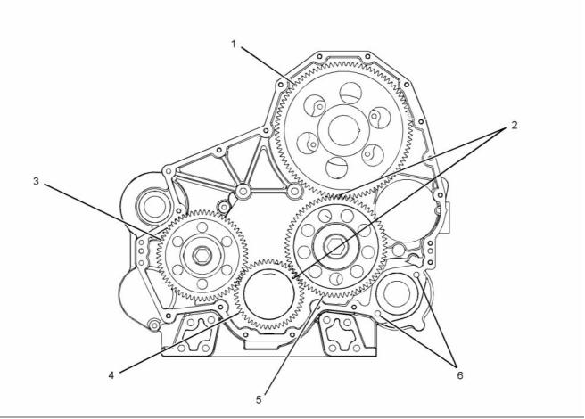
GearGroup(Front)
g01098608
Illustration 50
(6)Tappedholes foraccessory drive
(1) Camshaft gear
(4) Crankshaft gear
Numberofteeth.............................................. 96
Borediameter ...................... 58.900±0.013mm
(2.3189 ±0.0005 inch)
Number ofteeth.............................................. 48
Borediameter .......................... 96.90±0.02mm
(3.815 ±0.001 inch)
(2) Align thetiming marks ontheidler gear tothe
timingmarksonthecamshaftgearandthemarks
onthecrankshaft gear.
(5) Idler gear
Number ofteeth.............................................. 71
Borediameter forbearing .... 74.452±0.015mm
(2.9312 ±0.0006 inch)
(3) Idlergearforthewater pump
Bore diameter of the
Numberofteeth.............................................. 64
Borediameter forbearing.... 60.163±0.015mm
(2.3686 ±0.0006 inch)
bearing................................. 68.780±0.193mm
(2.7079 ±0.0076 inch)
Bore diameter of the
bearing................................. 55.281±0.039mm
(2.1764 ±0.0015 inch)
This document is printed from SPI². Not for RESALE
![]()
![]()
28
Specifications Section
KENR6905
i02796863
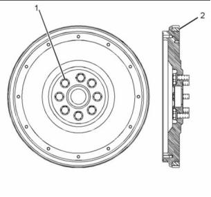
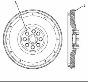
Flywheel
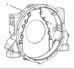
g01525652
Illustration 52
Apply asmall amount ofTooling(A)onthegasket
surface of the flywheel housing. Assemble the
flywheel housing tothecylinder block and tighten
withintenminutes ofapplying thesealant.
g01071339
Illustration 51
i02796865
Note: Refer to System Operation, Testingand
Adjusting forthecorrect method ofinspecting the
flywheel.
FlywheelHousingCover
(1) Bolt
(2) Ring gear
(1) Tightenthe bolts thathold the flywheel tothe
crankshaft.
Tighten the bolts to the following
torque........................... 300±40N·m(220±30lbft)
i02796864
FlywheelHousing
Table9
Required Tools
Tool
PartNumber
Part
Description
g01072994
Illustration 53
A
CH10879
Liquid Gasket
(1) Bolt
This document is printed from SPI². Not for RESALE
![]()

![]()
KENR6905
29
Specifications Section
Tighten the three bolts on the cover to the
following torque. ....................... 48N·m(35lbft)
i02796859
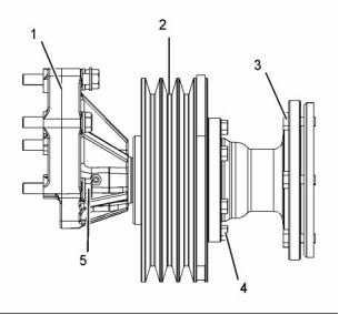
FanDrive
i02796227
BeltTightener
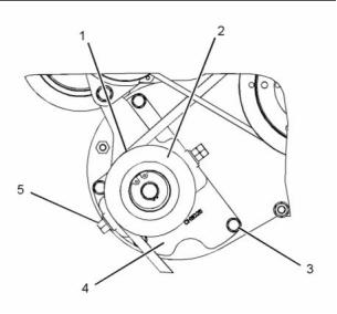
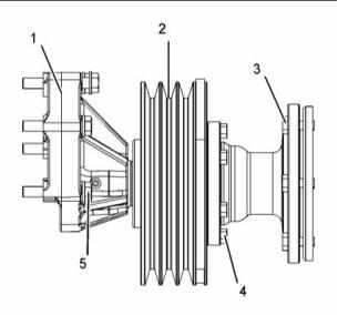
g01525682
Illustration 55
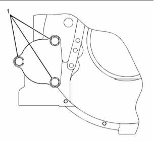
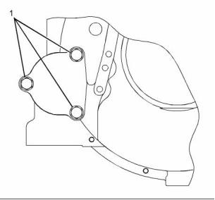
(1) Fandrive assembly
(2) Pulley
g01525651
Illustration 54
Typical example
(3) Tighten the bolts to the following torque.
.................................................. 47N·m(35lbft)
(1) Nut
Tightenthenuttothefollowingtorque. ..102N·m
(75 lb ft)
(4) TightentheBoltstothefollowingtorque. ..47N·m
(35 lb ft)
(2) Pulley
(3) Bolt
(5) Tighten the Bolts to the following
torque. .................................... 105N·m(77lbft)
Tightenthenuttothefollowing torque.....47N·m
(35 lb ft)
Note: Rotate bolt(3)inorder toadjust thetension
oftheV-belts. Refer toOperation andMaintenance
Manual, “Belts -Inspect/Adjust/Replace” formore
information.
(4) Belt Tightener
(5) TensionBolt
This document is printed from SPI². Not for RESALE
![]()
![]()
30
Specifications Section
KENR6905
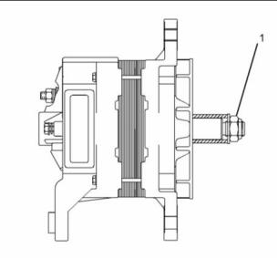
i02796212
Minimum fullloadcurrentat2000rpm ......... 35Amp
Turnonspeed............................................ 2300rpm
Outputvoltage ....................................... 27.5±0.3V
(1) Pulleynut.....................102±7N·m(75±5lbft)
AlternatorandRegulator
(2) Positive batteryterminal .............. 11.3±2.3N·m
(100 ±20lbin)
(3) Negative batteryterminal...............6.2±0.6N·m
(55±5lb in)
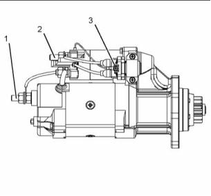
i02796840
ElectricStartingMotor
g01074003
Illustration 56
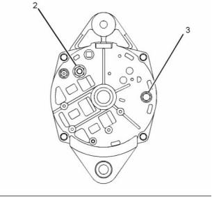
g01525644
Illustration 58
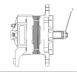
g01074005
Illustration 57
Voltage............................................................... 24V
Amperage ..................................................... 70Amp
Polarity ............................................ Negative ground
Rotation ............................................ Eitherdirection
Minimum fullloadcurrentat5000rpm ......... 75Amp
This document is printed from SPI². Not for RESALE
![]()
![]()
![]()
KENR6905
31
Specifications Section
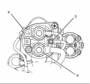
(6) Motor terminal
Tighten the nut onthe battery terminal tothe
following torque. ......30.5±3.5N·m(22±3lbft)
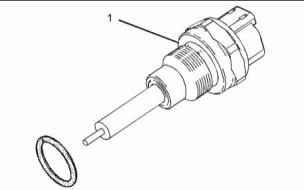
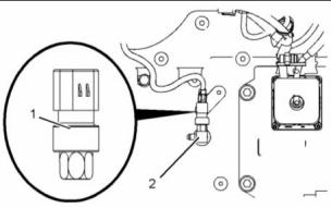
i02796276
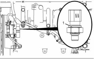
CoolantTemperatureSensor
g01525646
Illustration 59
When the electric starting motor isviewed from
the drive end, the motor rotates in the following
direction. ................................................... Clockwise
g01291117
Illustration 60
Noloadconditions at25°C(77°F)
Typical example
Minimum speed ..................................... 106rpm
Maximum output ...................................... 7.8kW
Voltage......................................................... 24V
(1) Sensor assembly
Tighten the sensor assembly tothe following
torque. ..................................................... 20N·m
(15 lb ft)
(1) Ground terminal
Tighten thenut on thebattery terminal tothe
following torque. ......30.5±3.5N·m(22±3lbft)
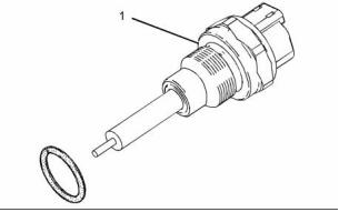
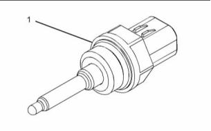
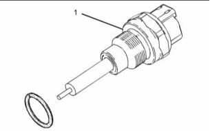
i02797035
FuelTemperatureSensor
(2) Battery terminal
Maximum number ofcable or wire terminals
between thenuts .............................................. 3
Tighten thenut on thebattery terminal tothe
following torque. ......30.5±3.5N·m(22±3lbft)
(3) Starter relay terminal
Tighten thenut on thebattery terminal tothe
following torque. .....1.7±0.25N·m(15±2lbin)
(4) Ground terminal
Tighten thenut on thebattery terminal tothe
following torque. ...2.25±0.25N·m(20±2lbin)
(5) Switch terminal
Tighten thenut on thebattery terminal tothe
following torque. ...2.25±0.25N·m(20±2lbin)
g01178443
Illustration 61
Note:Thewireterminalthatisontheswitchterminal
mustbeinsulated withheatshrinktubing.Donotuse
molded terminals.
(1) Sensor assembly
Tighten the sensor assembly tothe following
torque. ........................... 20±3N·m(15±2lbft)
This document is printed from SPI². Not for RESALE
![]()
![]()
32
Specifications Section
KENR6905
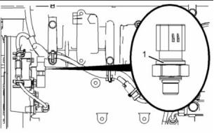
i02796853
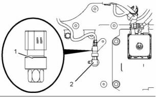
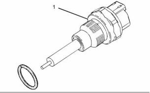
i02797079
EngineOilPressureSensor
InletAirTemperatureSensor
g01382381
g01291117
Illustration 62
Illustration 64
Typical example
Typical example
(1) Sensor assembly
(1) Sensor assembly
Tighten sensor assembly to the following
torque.............................................. 10N·m(90lbin)
Torqueforsensor ............................ 20N·m(15lbft)
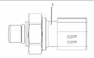
i02797099
InletManifold AirPressure
Sensor
i02796219
AtmosphericPressureSensor
g01388477
Illustration 63
g01291505
Illustration 65
Typical example
Typical example
(1) Sensor assembly
(1) Tighten the sensor to the following
torque. ...................................... 10N·m(90lbin)
Tighten the sensor assembly to the following
torque.............................................. 10N·m(90lbin)
This document is printed from SPI². Not for RESALE
![]()
KENR6905
33
Specifications Section
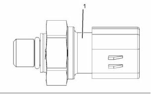
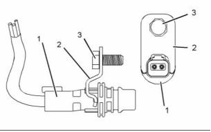
i02797163
Ensure thatthebracketisinstalled intheorientation
that isshown.
Speed/TimingSensor
CrankshaftPositionSensor
(3) Tightentheboltforthesensor tothefollowing
torque. ...................................... 25N·m(18lbft)
Ensure thatthesensor isseated before theboltis
tightened.
g01291129
Illustration 66
Typical example
(1) Sensor
(2) Bracket
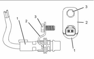
Ensure thatthebracket isinstalled intheorientation
that isshown.
(3) Tightentheboltforthesensor tothefollowing
torque. ...................................... 25N·m(18lbft)
Ensure thatthesensor isseated before theboltis
tightened.
CamshaftPositionSensor
g01291129
Illustration 67
Typical example
(1) Sensor
(2) Bracket
This document is printed from SPI². Not for RESALE
![]()
34
Index Section
KENR6905
Index
A
H
Alternator andRegulator....................................... 30
Atmospheric PressureSensor............................... 32
Housing (Front)...................................................... 26
I
B
Important SafetyInformation.................................
2
BeltTightener........................................................ 29
InletAirTemperatureSensor................................. 32
InletManifold AirPressure Sensor........................ 32
C
M
Camshaft............................................................... 14
Connecting Rod..................................................... 24
Connecting RodBearingJournal........................... 23
Coolant TemperatureSensor................................. 31
Crankshaft ............................................................ 21
Crankshaft Seals................................................... 22
Cylinder Block........................................................ 19
Cylinder Head........................................................ 11
Cylinder HeadValves............................................ 10
Cylinder Liner........................................................ 21
MainBearing Journal............................................. 23
P
PistonandRings................................................... 24
PistonCoolingJet.................................................. 25
S
E
Specifications Section........................................... 4
Speed/Timing Sensor............................................ 33
Camshaft PositionSensor................................. 33
Crankshaft Position Sensor............................... 33
Electric Starting Motor........................................... 30
Electronic UnitInjector...........................................
Electronic UnitInjectorMechanism.......................
Electronic UnitInjectorRockerArm.......................
Electronic UnitInjectorWiring...............................
EngineDesign.......................................................
6
7
7
8
4
T
EngineOilFilterBase............................................ 15
EngineOilPan....................................................... 17
EngineOilPressure Sensor.................................. 32
EngineOilPump.................................................... 16
Exhaust Elbow....................................................... 14
Exhaust Manifold................................................... 13
TableofContents...................................................
3
Turbocharger......................................................... 13
V
ValveMechanism ..................................................
ValveMechanism Cover........................................
9
9
F
VibrationDamper................................................... 22
FanDrive............................................................... 29
Flywheel................................................................ 28
Flywheel Housing.................................................. 28
Flywheel Housing Cover........................................ 28
W
WaterLines........................................................... 17
WaterPump........................................................... 19
WaterTemperatureRegulator............................... 18
WaterTemperatureRegulator Housing................. 18
FuelFilter(Primary)...............................................
FuelFilterBase.....................................................
FuelPrimingPump................................................
5
5
6
FuelTemperatureSensor...................................... 31
FuelTransferPump...............................................
4
G
GearGroup(Front)................................................ 27
This document is printed from SPI². Not for RESALE
![]()
免费热线
400-100-8969 15088860848
400-100-8969 15088860848
机组销售
0574-26871589 15267810868
0574-26871589 15267810868
配件销售
0574-26886646 15706865167
0574-26886646 15706865167
维修热线
0574-26871569 18658287286
0574-26871569 18658287286
手机端

微信公众号