麦克福斯约翰迪尔发动机零配件
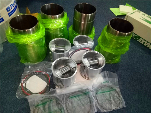
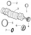
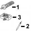
约翰迪尔 3029 2.9T 活塞(米) RE61270
|
|
|
发动机和设备型号
|
孔径:
4.19 in 106.5 mm
销径 Ø:
1.62 in 41 mm
|
|
|
强鹿JOHN DEERE柴油机配件、发动机配件、发电机组:
P124866、P124867、P551130、P777638、P181099、P772579、P827653、P771548、P771548、P827653、P772579、P772580、P829333、P13194、P550388、C125017、C125004、P772579、C085001、C085002、C085003、C085004、ECB105012、C105003、AF1913、AF4539、C105004、RE533026
ouo1080,0000234 –19–08may02–2/2 a c d c e f g h m i l j k b rg12162 –un–10may02 adjustable fan drive assembly a—plug e—snap ring h—washer k—sleeve b—bearing housing f—seal i—cap screw l—idler pulley c—bearing g—hub j—cap screw m—spacer d—shaft assemble fan drive assembly 1 pack inner&outer bearings (c) with ty6333 or ty6347 high temperature grease apply clean engine oil to bearing i d &shaft o d important: apply force to bearing inner race only 2 support end of shaft (d)&install bearings against shoulder 3 support bearing housing (b) on a firm flat surface with bearing bore in the upward position 4 install bearing&shaft assembly into housing 5 determine proper snap ring (e) thickness needed to obtain specified end play specification fan drive shaft—max end play 0 25 mm (0 0098 in ) 6 install snap ring in housing groove visually inspect snap ring installation for proper seating in housing groove 7 apply a thin coat of clean engine oil to o d of seal (f)&to seal lips install seal in housing bore until flush with housing 8 install plug (a) in rear of housing to specified height above housing face specification fan drive housing plug— height 5 9—6 5 mm (0 2323—0 2559 in ) 9 apply clean engine oil to i d of fan hub (g) and push onto shaft until it bottoms against shoulder 10 install washer (h)&cap screw (i) tighten cap screw to specifications specification fan hub-to-fan shaft—torque 125 n?m (92 lb-ft) 11 install idler pulley if removed torque idler retaining cap screw to specification specification fan drive idler cap screw— torque 50 n?m (37 lb-ft) ctm104 (11jul02) 02-070-30 powertech? 4 5 l & 6 8 l diesel engines 071102 pn=414 cooling system 02 070 31 rg,25,jw7547 –19–15may02–1/4 install fan drive assembly rg10375 –un–13oct99 fan height (poly-vee belt) a—fan height distance alt—alternator cp—crank pulley fd—fan drive i—idler wp—coolant pump important: be sure adjustable fan drive assembly is installed in correct position as removed to ensure proper belt tension 1 for engines using poly-vee belts: if reference marks were not made on timing gear cover during removal of fan drive assembly, use the following table to determine proper fan height poly-vee belt (manual tensioner) 4 5 l fan belt fan height 6 8 l fan belt option option 290 mm (11 42 in ) w/idler pulley (a) 240a, 240b, 240c, 24bk 240d 338 mm (13 31 in ) (a) 240e 240f 402 mm (15 83 in ) (a) 240g, 240h, 240j, 240k 24bj continued on next page ctm104 (11jul02) 02-070-31 powertech? 4 5 l & 6 8 l diesel engines 071102 pn=415 cooling system 02 070 32 rg,25,jw7547 –19–15may02–2/4 rg9128 –un–01jul98 fan height (poly-rib belt) a—fan height distance b—fan height distance c—fan height distance alt—alternator cp—crank pulley acc—air conditioning compres*** fd—fan drive i—idler t—tensioner wp—coolant pump 2 for engines using poly-rib-belts: if reference marks were not made on timing gear cover during removal of fan drive assembly, use figure to the right&following table to determine proper fan height poly-rib belt 4 5 l fan belt fan height 6 8 l fan belt option option 210 mm (8 27 in ) w/idler pulley (a) 24ag, 24ah, 24aj, 24aj, 24an 24ak, 24al, 24am 226 mm (8 9 in ) w/idler pulley (a) 2406, 2408, 2415, 2401, 2402, 2403, 2435, 2436, 2461, 2405, 2407, 2412, 240p, 240q 2471, 2472, 2473, 2474, 240t, 240w 258 mm (10 16 in ) w/idler pulley (a) 24ar, 24at 24bt 290 mm (11 42 in ) w/idler pulley (a) 2404, 2407, 2409, 2409, 2411, 2413, 2410, 2411, 2412, 2414, 2415, 2435, 2437, 2439, 2440, 2438, 2475, 2476, 2458, 2459, 2460, 240r, 240s, 240v 2462, 240u 338 mm (13 31 in ) (b) 2416, 2417, 2419, 2416, 2418, 2420, 2420, 2421, 2423, 2421, 2422, 2423, 2424, 2442, 2443, 2424, 2441, 2477, 2463, 2466, 2468 2478, 2479, 2482 402 mm (15 83 in ) (b) 2426, 2428, 2430, 2417, 2419, 2425, 2431, 2432, 2444, 2427, 2429, 2480 2445, 2464, 2465, 2469, 2470 402 mm (15 83 in ) w/idler pulley (c) 2434, 2446 2433 ctm104 (11jul02) 02-070-32 powertech? 4 5 l & 6 8 l diesel engines 071102 pn=416 continued on next page cooling system 02 070 33 rg,25,jw7547 –19–15may02–3/4 rg8116a –un–15jan98 fan drive mounting rg7974b –un–14nov97 fan drive hub a—cap screw position c—fan drive hub note: cap screw position (a) is used as an example only position of fan drive varies by application 3 install hub (c) with fan drive assembly, in positions (a) marked during disassembly,&tighten cap screws to specifications specification fan drive assembly-to-timing cover cap screws—torque 70 n?m (52 lb-ft) rg,25,jw7547 –19–15may02–4/4 rg7937e –un–13nov97 c—fan pulley fan pulley 4 install fan pulley (c)&tighten cap screws to specifications specification fan pulley-to-pulley hub m8 cap screws—torque 35 n?m (26 lb-ft) fan pulley-to-pulley hub m10 cap screws—torque 70 n?m (52 lb-ft) 5 install poly-vee belt be sure belt is correctly seated in all pulley grooves ctm104 (11jul02) 02-070-33 powertech? 4 5 l & 6 8 l diesel engines 071102 pn=417 cooling system 02 070 34 dpsg,ouo1004,2508 –19–05jan00–1/1 remove&install fan drive assembly (2254 combine) cd30795 –un–15nov99 fan drive assembly cd30722 –un–22feb99 pulley-to-bracket distance a—bearing shaft b—fan bracket c—pulley d—idler axle shaft e—idler f—bearing shaft end g—distance for pulley installation h—spacer j—nut k—screw l—nut m—cap screw n—spacer 1 remove parts (a—e)&(h—n) as required 2 inspect&replace parts as necessary 3 press bearing shaft (a) into fan bracket (b) until bearing face is flush with bracket end face 4 place fan bracket under a press so that the thrust, when pressing on pulley, is received only by the bearing shaft end (f) press pulley until distance (g) is obtained specification rear housing face-to-hub front face—distance 123 5 mm (4 862 in ) 5 install fan bracket on engine&tighten hardware to specifications fan drive assembly (2254 combine)—specification fan idler axle shaft-to-block (d)—torque 340 n?m (251 lb-ft) fan idler-to-shaft retaining nut (j)—torque 225 n?m (166 lb-ft) fan drive bracket-to-block cap screw (k)—torque 340 n?m (251 lb-ft) fan drive bracket-to-cylinder head cap screws (m)—torque 140 n?m (103 lb-ft) upper fan drive bracket-to-lower bracket cap screws/nuts (l)—torque 140 n?m (103 lb-ft) ctm104 (11jul02) 02-070-34 powertech? 4 5 l & 6 8 l diesel engines 071102 pn=418 cooling system 02 070 35 rg,25,jw7546 –19–20nov97–1/2 remove&install coolant heater (if equipped) ts210 –un–23aug88 electrical shock safety rg9082 –un–12mar98 coolant heater rg5619 –un–31oct97 coolant heater a—cord b—dust cover c—retaining nut d—adapter e—gasket f—o-ring g—heater element caution: to avoid shock/hazardous operation, always use a three-wire heavy-duty electrical cord equipped with three-wire connectors if a two-to-three contact adapter is used at the wall receptacle, always connect green wire to a good ground keep electrical connectors clean to prevent arcing only plug coolant heater into electrical power if heating element is immersed in coolant sheath could burst&result in personal injury 1 unplug heater from electrical power source 2 drain cooling system 3 disconnect cord (a) from heater assembly 4 loosen retaining nut (c)&remove adapter (d) and heater element from block 5 inspect&replace parts as necessary note: the heater element (g) cannot be repaired replace if defective 6 install a new gasket (e) apply jdt308 soap lubricant to new o-ring (f)&install 7 install heater element through adapter (d)&install nut (c) loosely 8 install heater into cylinder block with element pointing to the rear 9 tighten adapter (d) 10 turn element clockwise&then counterclockwise until element contacts casting move element midway between contact points 11 hold element with a wrench&tighten retaining nut (c) to specifications specification coolant heater lock nut—torque 35 n?m (26 lb-ft) ctm104 (11jul02) 02-070-35 powertech? 4 5 l & 6 8 l diesel engines 071102 pn=419 continued on next page cooling system 02 070 36 rg,25,jw7546 –19–20nov97–2/2 note: if heater has been ordered as an attachment only, it will include a dust cover (b) the cover is used to protect the electrical connectors when cord assembly (a) has been removed 12 install cord 13 service engine with coolant dpsg,ouo1004,1062 –19–29sep99–1/1 remove&install cold start advance switch (if equipped) rg9143 –un–18may98 cold start switch a—connector b—switch 1 drain coolant from thermostat housing 2 disconnect connector (a)&remove switch (b) 3 install switch with new o-ring in thermostat housing and tighten to specifications specification cold start switch—torque 5 n?m (44 lb-in ) 4 connect harness connector ctm104 (11jul02) 02-070-36 powertech? 4 5 l & 6 8 l diesel engines 071102 pn=420 group 080 air intake&exhaust system 02 080 1 rg,30,jw7583 –19–20nov97–1/2 extending turbocharger life turbochargers are designed to last the life of the engine, but because they operate at such high speeds (100,000 rpm/more), a moment’s carelessness can cause them to fail in seconds the major causes of turbocharger failures are attributed to: ? lack of lube oil (quick starts&hot shutdowns) ? oil contamination ? ingestion of foreign objects ? restricted oil drainage ? low oil level ? operation on excessive side slopes ? abnormally high exhaust temperatures lack of lube oil oil not only lubricates the turbocharger’s spinning shaft and bearings, it also carries away heat when oil flow s***/is reduced, heat is immediately transferred from the hot turbine wheel to the bearings, which are also heating up because of the increased friction due to the lack of oil this combination causes the turbocharger shaft temperature to increase rapidly if oil flow does not increase&the process continues, bearings will fail once the bearings fail (which can happen in just seconds), seals, shaft, turbine and compres*** wheels can also be damaged the principal causes of turbocharger bearing lubrication problems are low oil pressure, a bent, plugged/undersized oil lube supply line, plugged or restricted oil galleries in the turbocharger,/improper machine start-up&shutdown procedures oil levels&pressure should always be closely monitored&all worn hoses&lines should be replaced the turbocharger oil supply line should be checked frequently to make sure it is not kinked or bent,&it should always be replaced with a line of equal size, length&strength the easiest way to damage a turbocharger is through improper start-up&shutdown procedures always idle the engine for at least 30 seconds (no load) after start-up&before shutdown warming the engine up before applying a load allows oil pressure to build up and lines to fill with oil idling the engine before shutdown allows the engine and turbocharger to cool “hot” shutdowns can cause the turbocharger to fail because, after high-speed operation, the turbocharger will continue to rotate long after the engine has been shut off&oil pressure has dropped to zero this will cause heat to build up and possible bearing damage it can also cause carbon and varnish deposits to form oil contamination a second cause of turbocharger failures is contaminated oil it can be caused by a worn or damaged oil filter/not changing the lube oil at recommended intervals expecting the oil filter to remove dirt, sand, metal chips, etc , from the oil before they reach the engine/turbocharger can be a costly mistake because contaminated oil may completely bypass the engine oil filter if the oil filter/oil cooler is clogged, if the filter element is improperly installed, or if the oil is thick during cold weather four good ways of avoiding oil contamination are: ? always inspect the engine thoroughly during major overhaul look especially for any sludge/debris left in lube oil galleries ? change lube oil at recommended intervals analysis of oil samples at filter change periods can help identify potentially harmful contaminants in the oil ? clean the area around the oil fill cap before adding oil ? use a clean container when adding oil ctm104 (11jul02) 02-080-1 powertech? 4 5 l & 6 8 l diesel engines 071102 pn=421 continued on next page air intake&exhaust system 02 080 2 rg,30,jw7583 –19–20nov97–2/2 ingestion of foreign objects a third cause of turbocharger damage is the ingestion of foreign objects foreign objects/particles can be ingested&cause damage to the turbocharger on both compres***&turbine sides this is easy to avoid on the compres*** side, foreign objects usually take the form of dust, sand,/shreds of air cleaner element that enter through improperly installed air cleaner elements leaky air inlet piping (loose clamps or torn rubber joints)/torn pleats in dry-type air cleaner elements also create problems the result is erosion of compres*** blades that can cause the delicately balanced wheel to wobble important: whenever an internal engine failure (valve, valve seat, piston) occurs, a thorough inspection of the turbocharger must be performed before returning engine to service restricted oil drainage a fourth cause of turbocharger damage is restricted lube oil drainage the lubricating oil carries away heat generated by friction of the bearings&from the hot exhaust gases if drainage back to the sump is impeded, the bearings will overheat with damage that will ultimately lead to failure there are two primary reasons for restricted drainage a blocked drain tube, due to either damage/a buildup of sludged oil,/high crankcase pressure, which can be due to restricted crankcase breather or excessive engine blow-by periodically check both the turbocharger oil drain tube and engine breather tube for damage/restriction correction of these conditions leads to longer turbocharger life abnormally high exhaust temperatures a fifth cause of turbocharger damage is abnormally high exhaust temperatures elevated exhaust temperatures cause coking of oil which can lead to bearing failure extreme over-temperature operation can cause wheel burst there are two basic causes of over-temperature the first is restricted air flow&the second is overpowering the engine in either case the engine has more fuel than available air for proper combustion; this overfueled condition leads to elevated exhaust temperatures causes of restricted air flow can include damaged inlet piping, clogged air filters, excessive exhaust restriction, or operation at extreme altitudes overpowering generally is due to improper fuel delivery/injection timing if overtemperature operation has been identified, an inspection of the air inlet&exhaust systems should be performed also, check the fuel delivery&timing ctm104 (11jul02) 02-080-2 powertech? 4 5 l & 6 8 l diesel engines 071102 pn=422 air intake&exhaust system 02 080 3 rg,30,jw7582 –19–27sep99–1/1 remove turbocharger rg7618a –un–06nov97 remove turbocharger rg7619a –un–06nov97 disconnect turbocharger lines a—hose clamp b—oil inlet line c—oil return pipe d—turbocharger caution: after operating engine, allow exhaust system to cool before removing turbocharger important: when cleaning turbocharger, do not spray directly into compres*** cover or turbine housing if turbocharger inspection is required, do not clean exterior prior to removal doing so may wash away evidence of a potential failure mode see turbocharger inspection later in this group ) 1 thoroughly clean exterior of turbocharger and surrounding area to prevent entry of dirt into the air intake system during removal 2 remove air intake hose&exhaust elbow (shown removed) loosen hose clamp (a) 3 disconnect oil inlet line (b)&oil return pipe (c) from turbocharger (d) 4 remove mounting cap screws&nuts&lift turbocharger from exhaust manifold remove stainless steel gasket 5 place turbocharger on a clean flat surface cap/plug all air intake&exhaust openings 6 perform turbocharger inspection as described later, if failure mode has not yet been determined (see turbocharger inspection in this group ) ctm104 (11jul02) 02-080-3 powertech? 4 5 l & 6 8 l diesel engines 071102 pn=423 air intake&exhaust system 02 080 4 rg,rg34710,1258 –19–23oct97–1/2 turbocharger failure analysis the following is a guide for diagnosing the cause of turbocharger failures after removal from the engine problem possible cause suggested remedy compres*** housing inlet defects foreign object damage objects left in intake system disassemble&inspect intake system for foreign objects (this group) inspect engine for internal damage leaking and/or defective intake system inspect air intake system connections including air filter; repair as required (this group) inspect air intake related engine components compres*** wheel rub bearing failure determine if engine and/or operator contributed to lack of lubrication, contaminated lubrication, excessive temperature,/debris generating engine failure in progress correct as required manufacturing defects correct as required (this group) compres*** housing outlet defects oil and/or dirt in housing restricted air intake system inspect&clean air cleaner prolonged periods of low rpm engine check with operator to confirm conditions (see idling operator’s manual ) defective oil seal ring repair as required (this group) restricted oil drain line inspect&clear oil drain line as required turbine housing inlet defects oil in housing internal engine failure inspect&repair engine as required oil leaking from compres*** housing verify that oil is in compres*** housing&refer to seal “compres*** housing outlet defects” as listed earlier in this chart center wall deteriorated excessive operating temperature check for restricted air intake check engine for overfueling check injection pump timing continued on next page ctm104 (11jul02) 02-080-4 powertech? 4 5 l & 6 8 l diesel engines 071102 pn=424 air intake&exhaust system 02 080 5 rg,rg34710,1258 –19–23oct97–2/2 turbine housing outlet defects turbine wheel rub bearing failure determine if engine and/or operator contributed to lack of lubrication, contaminated lubrication, excessive temperature,/debris generating engine failure in progress correct as required manufacturing defect correct as required (this group) foreign object damage internal engine failure 克拉玛依强鹿滤芯滤清器RE39527批发,怒江约翰迪尔强鹿AT365870旋装式油水分离燃油滤清器代理商,深圳JohnDeere空气加热器供应商,自贡johndeere约翰迪尔强鹿柴油机风扇哪里买,金华强鹿6068柴油机凸轮轴衬套厂家价格,大兴安岭johndeere约翰迪尔强鹿柴油发动机增压器RE509435批发价,沈阳约翰迪尔强鹿3029el36936喷油器哪里买,九江强鹿滤芯滤清器RE58367哪家买,锦州强鹿柴油发电机配件找哪家,延安johndeere约翰迪尔强鹿6090发动机配件厂家供应,昌都强鹿柴油机活塞RE527039厂家供货,黔东南约翰迪尔装载机发动机涡轮增压器供应商,黄石强鹿柴油机活塞环RE515941供货商,台南强鹿机油滤芯现货代理商,柳州约翰迪尔4045柴油机机油冷却器RE59298批发商,宣城JohnDeere进气门RE531221的价格, inspect&repair engine as required objects left in intake system disassemble&inspect air intake system (this group) leaking air intake system correct as required (this group) oil and/or excessive carbon internal engine failure verified by oil in turbine housing correct as required turbine seal failure inspect for excessive heat from overfueling and/or restricted air intake prolonged periods of low rpm engine ask operator to run engine under load/at a higher idling rpm (see operator’s manual) restricted oil drain line inspect&clear oil drain line as required external center housing&joint defects leaks from casting defective casting replace turbocharger (this group) defective gasket verify if leaks are occurring at gasket joints leaks from joints loose attaching screws tighten to specifications (this group) defective gasket inspect&repair as required internal center housing defects excessive carbon build-up in housing hot engine shutdown review proper operation with operator as shown in or on shaft operator’s manual excessive operating temperature restricted air intake; overfueling/mistimed engine restricted oil drain line inspect&clean oil drain lines as required operating engine at high speeds&idle engine for a few minutes to allow oil to reach loads immediately after start-up bearings before applying heavy loads ctm104 (11jul02) 02-080-5 powertech? 4 5 l & 6 8 l diesel engines 071102 pn=425 air intake&exhaust system 02 080 6 rg,30,jw7574 –19–19sep01–1/12 turbocharger inspection the following inspection procedure is recommended for systematic failure analysis of a suspected failed turbocharger this procedure will help to identify when a turbocharger has failed,&why it has failed, so the primary cause of the failure can be corrected proper diagnosis of a non-failed turbocharger is important for two reasons first, identification of a non-failed turbocharger will lead to further investigation&repair of the cause of a performance complaint second, proper diagnosis eliminates the unnecessary expense incurred when a non-failed turbocharger is replaced the recommended inspection steps, which are explained in detail on following pages, are: ? compres*** housing inlet&compres*** wheel ? compres*** housing outlet ? turbine housing inlet ? turbine housing outlet&turbine wheel ? external center housing&joints ? perform axial bearing end play test note: to enhance the turbocharger inspection, an inspection sheet (form no df-2280 available from distribution service center—english only) can be used that lists the inspection steps in the proper order&shows potential failure modes for each step check off each step as you complete the inspection&record any details or problems obtained during inspection retain this with the work order for future reference continued on next page ctm104 (11jul02) 02-080-6 powertech? 4 5 l & 6 8 l diesel engines 071102 pn=426 air intake&exhaust system 02 080 7 rg,30,jw7574 –19–19sep01–2/12 rg4523 –un–03nov97 checking inlet&compres*** wheel a—compres*** wheel compres*** housing inlet&compres*** wheel 1 check compres*** inlet&compres*** wheel (a) for foreign object damage note: foreign object damage may be extensive or minor in either case, the source of the foreign object must be found&corrected to eliminate further damage 2 mark findings on your checklist&continue the inspection rg,30,jw7574 –19–19sep01–3/12 rg4524 –un–05dec97 checking compres*** inlet note: you will need a good light source for this check 3 check compres*** inlet for wheel rub on the housing (arrow) look very closely for any score marks on the housing itself&check the tips of the compres*** wheel blades for damage continued on next page ctm104 (11jul02) 02-080-7 powertech? 4 5 l & 6 8 l diesel engines 071102 pn=427 air intake&exhaust system 02 080 8 rg,30,jw7574 –19–19sep01–4/12 rg4525 –un–05dec97 checking compres*** outlet a—compres*** housing outlet compres*** housing outlet 1 check compres*** housing outlet (a) the outlet should be clean&free of dirt/oil 2 mark it on your checklist if dirt/oil is found and continue the inspection rg,30,jw7574 –19–19sep01–5/12 rg4526 –un–05dec97 checking turbine housing inlet ports turbine housing inlet check the turbine housing inlet ports (arrow) for oil in housing, excessive carbon deposit/erosion of center walls note: if the inlet is wet with oil,/has excessive carbon deposits, an engine problem is likely center wall erosion (cracking/missing pieces), indicates excessive exhaust temperature continued on next page ctm104 (11jul02) 02-080-8 powertech? 4 5 l & 6 8 l diesel engines 071102 pn=428 air intake&exhaust system 02 080 9 rg,30,jw7574 –19–19sep01–6/12 rg4527 –un–05dec97 checking turbine wheel&outlet a—turbine housing outlet b—blades turbine housing outlet&turbine wheel 1 use a flashlight to look up inside the turbine housing outlet (a)&check blades (b) for foreign object damage rg,30,jw7574 –19–19sep01–7/12 rg4528 –un–05dec97 checking turbine wheel blades 2 inspect the wheel blades&housing for evidence of wheel rub (arrow) wheel rub can bend the tips of the blades with the housing showing wear/damage continued on next page ctm104 (11jul02) 02-080-9 powertech? 4 5 l & 6 8 l diesel engines 071102 pn=429 air intake&exhaust system 02 080 10 rg,30,jw7574 –19–19sep01–8/12 rg4532 –un–05dec97 checking shaft rotation&clearance 3 rotate the shaft, using both hands, to check rotation and clearance the shaft should turn freely; however, there may be a slight amount of drag rg,30,jw7574 –19–19sep01–9/12 rg4533 –un–05dec97 checking for contact of compres***&turbine wheels important: use only moderate hand force (3— 4 pounds) on each end of shaft 4 next, pull up on the compres*** end of the shaft and press down on the turbine end while rotating shaft neither the compres*** wheel nor the turbine wheel should contact the housing at any point note: there will be some “play” because the bearings inside the center housing are free floating continued on next page ctm104 (11jul02) 02-080-10 powertech? 4 5 l & 6 8 l diesel engines 071102 pn=430 air intake&exhaust system 02 080 11 rg,30,jw7574 –19–19sep01–10/12 rg4529 –un–05dec97 checking center housing external center housing&joints visually check the outside of the center housing, all connections to the compres***,&turbine housing for oil note: if oil is present, make sure it is not coming from a leak at the oil supply/return line important: before you finalize your conclusion that the turbocharger has not failed, it is strongly recommended that the following procedures of checking radial bearing clearance&axial bearing endplay with a dial indicator be performed these procedures are not required if a failure mode has already been identified continued on next page ctm104 (11jul02) 02-080-11 powertech? 4 5 l & 6 8 l diesel engines 071102 pn=431 air intake&exhaust system 02 080 12 rg,30,jw7574 –19–19sep01–11/12 rg7623 –un–06nov97 axial bearing&end play test perform axial bearing end play test this test will give an indication of the condition of the axial bearing within the center housing&rotating assembly 1 mount magnetic base dial indicator so that indicator tip rests on end of shaft preload indicator tip&zero dial on indicator 2 move shaft axially back&forth by hand 3 observe&record total dial indicator movement specification turbocharger (airesearch/garret)—axial bearing end play 0 025—0 102 mm (0 001—0 004 in ) turbocharger (cz)—axial bearing end play 0 11—0 16 mm (0 004—0 006 in ) turbocharger (schwitzer)—axial bearing end play 0 064—0 114 mm (0 0025—0 0045 in ) turbocharger (borgwarner/schwitzer)—axial bearing end play 0 14 mm (0 0055 in ) maximum if bearing end play is not within specification, replace turbocharger rg,30,jw7574 –19–19sep01–12/12 rg4534 –un–05dec97 checking shaft end play 4 next, check shaft endplay by moving the shaft back and forth (white arrows) while rotating there will be some endplay but not to the extent that the wheels contact the housings note: these diagnostic procedures will allow you to determine the condition of the turbocharger if the turbocharger has failed, analysis of your inspection notes should direct you to the specific areas of the engine to correct the problems causing the turbocharger failure see turbocharger failure analysis outlined earlier in this group it is not unusual to find that a turbocharger has not failed if your turbocharger passes all the inspections, the problem lies somewhere else ctm104 (11jul02) 02-080-12 powertech? 4 5 l & 6 8 l diesel engines 071102 pn=432 air intake&exhaust system 02 080 13 rg,30,jw7573 –19–15dec99–1/2 perform radial bearing clearance test rg7622 –un–06nov97 radial bearing clearance test this test will give an indication of the condition of the radial bearings within the center housing&rotating assembly note: prelube center housing bearings prior to performing radial clearance test (see prelube turbocharger, later in this group ) airesearch/garret turbocharger 1 position dial indicator with extension adapter onto center housing so that tip rests on shaft extending through oil return cavity important: use only moderate force (3—4 lb) on each end of the shaft when checking clearance 2 grasp rotating shaft at both ends&move the shaft toward the indicator then away from the indicator (arrows) by applying moderate force of 3—4 lb 3 observe&record total indicator movement specification turbocharger (airesearch/garret)—radial bearing clearance 0 08—0 18 mm (0 003—0 007 in ) 4 if total indicator reading is not within specification, replace turbocharger continued on next page ctm104 (11jul02) 02-080-13 powertech? 4 5 l & 6 8 l diesel engines 071102 pn=433 air intake&exhaust system 02 080 14 rg,30,jw7573 –19–15dec99–2/2 cd30658 –un–04may98 radial bearing clearance test borgwarner/schwitzer&cz turbochargers 1 remove compres*** cover 2 install a dial indicator against end of shaft as shown 3 move shaft alternately toward&away from indicator and record total travel compare reading with the following specification specification turbocharger (cz)—radial bearing clearance 0 37—0 46 mm (0 015—0 018 in ) turbocharger (borgwarner/schwitzer)—radial bearing clearance 0 51 mm (0 0200 in ) maximum 4 if total indicator reading is not within specification, replace turbocharger 5 install compres*** cover ctm104 (11jul02) 02-080-14 powertech? 4 5 l & 6 8 l diesel engines 071102 pn=434 air intake&exhaust system 02 080 15 dpsg,ouo1004,4 –19–31mar98–1/1 adjust turbocharger wastegate actuator (if equipped) rg9084 –un–16mar98 turbo wastegate a—jam nut b—rod end c—retainer clip d—bypass lever 1 loosen jam nut (a) 2 disconnect hose&pressurize actuator to 83 kpa ( 83 bar) (12 psi)&hold at this calibration pressure 3 push bypass lever (d) as far as possible toward the actuator&apply pressure to keep lever in that position important: twisting/forcing the entire rod in or out will change the calibration, causing damage to engine from overboost 4 turn rod end (b) in either direction until rod eye can just be slipped over bypass lever pin loosen rod end an additional half turn, install onto pin&secure with retainer clip (c) release pressure on actuator 5 pressurize the actuator to 83 kpa ( 83 bar) (12 psi) measure the end play with a dial indicator, moving the bypass assembly back&forth in a direction perpendicular to the actuator rod end play should be within specifications listed if necessary to adjust, set end play at 0 38 mm (0 015 in ) specification turbocharger—actuator end play 0 05—0 056 mm (0 002—0 022 in ) 6 vary the pressure from 62—83 kpa ( 62— 83 bar) (9— 12 psi) a few times to verify smooth&free operation of the bypass assembly 7 attach hose to actuator&secure with hose clamp ctm104 (11jul02) 02-080-15 powertech? 4 5 l & 6 8 l diesel engines 071102 pn=435 air intake&exhaust system 02 080 16 rg,30,jw7571 –19–20nov97–1/1 repair turbocharger turbochargers used on the engines covered in this manual are available through service parts as a complete remanufactured assembly only individual components for repair are not available rg,30,jw7570 –19–20nov97–1/1 prelube turbocharger rg7624 –un–23nov97 turbocharger pre-use lubrication important: do not spin the rotor assembly with compressed air damage to bearings can occur when using compressed air fill oil inlet/drain port with clean engine oil&spin rotating assembly (by hand) to properly lubricate bearings if turbocharger is to be stored for an extended period of time, lubricate internally&install protective covers on all openings ctm104 (11jul02) 02-080-16 powertech? 4 5 l & 6 8 l diesel engines 071102 pn=436 air intake&exhaust system 02 080 17 rg,30,jw7569 –19–17oct01–1/2 install turbocharger rg7618b –un–06nov97 install turbocharger rg7619b –un–06nov97 connect turbocharger lines a—hose clamp b—oil inlet line c—oil return pipe d—turbocharger important: if turbocharger failed because of foreign material entering the air intake system, be sure to examine the system and clean as required to prevent a repeat failure if not done previously, prime (prelube) the turbocharger rotating assembly prior to mounting turbocharger on engine prelube center housing with clean engine oil through the oil drain hole turn rotating assembly by hand to lubricate bearings important: turbochargers can be either single or dual entry make sure the appropriate single/dual gasket is used when installing turbocharger 1 position turbocharger (d)&new stainless steel gasket onto exhaust manifold tighten stud nuts to specifications specification turbocharger-to-exhaust manifold nuts—torque 70 n?m (52 lb-ft) 2 install oil return pipe (c) to turbocharger tighten oil return pipe cap screws to specifications specification turbocharger oil return pipe cap screws—torque 24 n?m (18 lb-ft) 3 connect turbocharger oil inlet line (b)&tighten to specifications specification turbocharger oil inlet line (at turbocharger)—torque 24 n?m (18 lb-ft) turbocharger oil inlet line (at oil filter header)—torque 24 n?m (18 lb-ft) 4 connect air inlet hose-to-turbocharger compres*** housing tighten hose clamp (a) on air inlet line to specifications specification turbocharger air inlet hose clamp—torque 6 n?m (4 5 lb-ft) (54 lb-in ) ctm104 (11jul02) 02-080-17 powertech? 4 5 l & 6 8 l diesel engines 071102 pn=437 continued on next page air intake&exhaust system 02 080 18 rg,30,jw7569 –19–17oct01–2/2 important: since the greatest suction force occurs between air cleaner&turbocharger, ensure that hose connections are tight to prevent entry of dirt into system 5 install exhaust adapter&exhaust elbow tighten cap screws&clamp to specifications specification exhaust adapter-to-turbocharger clamp—torque 7 5 n?m (5 5 lb-ft) (66 lb-in ) turbocharger exhaust elbow— torque 47 n?m (35 lb-ft) rg,30,jw7568 –19–20nov97–1/1 turbocharger break-in important: a new/repaired turbocharger does not have an adequate oil supply for immediate start-up of engine perform the steps below to prevent damage to turbocharger bearings 1 either push the throttle lever to the “stop” position, hold the engine shut-off knob out,/disconnect electrical wire from injection pump important: do not crank engine longer than 30 seconds at a time to avoid damage to starter motor 2 crank engine over with starter motor until oil pressure gauge needle registers within the “green” zone of pressure gauge 3 start&run engine at low idle while checking oil inlet and air piping connections for leaks ctm104 (11jul02) 02-080-18 powertech? 4 5 l & 6 8 l diesel engines 071102 pn=438 air intake&exhaust system 02 080 19 dpsg,ouo1004,5 –19–31mar98–1/1 recommendations for turbocharger use important: should the engine stall when operating under load, immediately restart the engine to prevent overheating of turbocharger parts in most cases, turbocharger damage is caused by improper start-up&shutdown procedures always idle the engine for at least 30 seconds (no load) after start-up and before shutdown ctm104 (11jul02) 02-080-19 powertech? 4 5 l & 6 8 l diesel engines 071102 pn=439 air intake&exhaust system 02 080 20 rg,30,jw7567 –19–18jun02–1/2 remove, inspect,&install exhaust manifold rg7794b –un–11nov97 exhaust manifold w/turbocharger installed rg7625b –un–06nov97 exhaust manifold gaskets rg7985 –un–14nov97 exhaust manifold guide studs—two valve head rg12403 –un–03jul02 exhaust port sleeve—four valve head a—exhaust manifold b—gasket c—guide studs d—exhaust port sleeve 1 remove turbocharger (if equipped), exhaust elbow, or exhaust pipe if desired turbocharger can be removed with exhaust manifold (a) (see remove turbocharger, earlier in this group ) 2 remove exhaust manifold two-valve head have guide studs (c) to aid in removal note: some engines are assembled with sealant in production replace with gaskets when servicing some exhaust manifolds are equipped with a one-piece gasket 3 remove gasket(s) (b) if equipped 4 remove exhaust port sleeves on four-valve head 5 inspect sleeves for cracks/wear replace as needed 6 clean mating surfaces of cylinder head&exhaust manifold with cleaning solvent, acetone,/any other suitable cleaner that will remove sealant, if previously applied (brake kleen, ignition cleaner&drier are examples of commercially available solvents that will remove sealant from flange ) thoroughly clean passages in exhaust manifold 7 inspect each exhaust manifold for cracks/damage inspect machined mounting surfaces for burrs/other defects which might prevent gasket(s) from sealing properly replace parts as needed 8 install gasket(s) (b) on exhaust manifold note: stainless steel gaskets can be reused if not damaged graphite gaskets must be replaced 9 install exhaust port sleeves for four-valve head ctm104 (11jul02) 02-080-20 powertech? 4 5 l & 6 8 l diesel engines 071102 pn=440 continued on next page air intake&exhaust system 02 080 21 rg,30,jw7567 –19–18jun02–2/2 10 install exhaust manifold use guide studs (c) if equipped 11 apply pt569 never-seez? compound to cap screws 12 tighten exhaust manifold-to-cylinder head cap screws to specifications on 6-cylinder engines, tighten cap screws on no 3&no 4 cylinders first on 4-cylinder engines, tighten no 2&no 3 cylinders first specification exhaust manifold-to-cylinder head cap screws—torque 70 n?m (52 lb-ft) never-seez is a registered trademark of emhart chemical group rg,30,jw7566 –19–20nov97–1/1 remove&install air-to-air aftercooler refer to machine technical manual for removal, inspection,&installation procedures ctm104 (11jul02) 02-080-21 powertech? 4 5 l & 6 8 l diesel engines 071102 pn=441 air intake&exhaust system 02 080 22 dpsg,ouo1004,6 –19–17oct01–1/1 remove&install air intake pipe rg9088 –un–19mar98 air intake pipe a—hose clamp b—cap screws note: configuration of air intake pipe varies by application engines may also be equipped with an air heater/spacer between intake pipe and manifold (see remove&install air heater next in this group ) 1 if required, disconnect start aid lines/wiring 2 remove cap screws (b) 3 loosen hose clamp (a)&remove air intake pipe 4 inspect&repair as required 5 install new gasket&air intake pipe tighten cap screws to specifications specification air intake pipe-to-cylinder head—torque 70 n?m (52 lb-ft) 6 tighten hose clamp (a) to specifications specification air intake pipe hose clamp— torque 6 n?m (4 5 lb-ft) (54 lb-in ) 7 if required, connect start aid lines/wiring ctm104 (11jul02) 02-080-22 powertech? 4 5 l & 6 8 l diesel engines 071102 pn=442 air intake&exhaust system 02 080 23 ouo1017,0000af1 –19–12jun02–1/1 remove, inspect,&install intake manifold (four-valve head) rg12404 –un–14jun02 intake manifold, four-valve head a—fuel line b—cap screw (2 used) c—prefilter d—cap screw (12 used) e—intake manifold note: position of fuel filters vary by engine type and engine application 1 remove fuel line (a) 2 remove two cap screws (b)&remove prefilter (c) 3 remove twelve cap screws (d)&remove intake manifold (e) 4 inspect for cracks/damage inspect machined mounting surfaces for burrs/other defects which might prevent gasket from sealing properly 5 install new gasket&install intake manifold tighten cap screws to specification specification intake manifold cap screws— torque 73 n?m (54 lb-ft) 6 install prefilter ctm104 (11jul02) 02-080-23 powertech? 4 5 l & 6 8 l diesel engines 071102 pn=443 air intake&exhaust system 02 080 24 dpsg,ouo1004,7 –19–18jun02–1/1 remove&install air heater (if equipped) rg9081 –un–16mar98 air heater (two versions shown) a—grid-type air heater b—gasket c—glow plug air heater note: figure shows two types of air heaters one/the other is used per application on later model grid-type air heaters, gasket (b) is replaced by an o-ring, eliminating the need for ground wire shown 1 disconnect wiring, if required 2 if machine is equipped with grid-type air heater (a), remove air intake pipe (see remove&install air intake pipe in this group ) 3 remove air heater (a)/(c) 4 replace parts as required 5 if equipped with grid-type air heater, install air heater (a) with new gasket (b)/o-ring coat threads of air heater (c) with loctite? 592 pipe sealant with teflon?&install 6 install air intake pipe if required 7 connect wiring, if required loctite is a registered trademark of loctite corp teflon is a registered trademark of du pont co ctm104 (11jul02) 02-080-24 powertech? 4 5 l & 6 8 l diesel engines 071102 pn=444 air intake&exhaust system 02 080 25 dpsg,ouo1004,995 –19–17oct01–1/1 remove&install starting aid (if equipped) t117494b –un–01oct98 starting aid tube t117496b –un–13oct98 1—starting aid tube nozzle holder 2—red dot for nozzle installation 3—orifice 1 disconnect starting aid tube (1) note: when removing nozzle, note the location of red dot (2) when removing 2 remove nozzle holder from air inlet 3 clean/replace nozzle holder as required 4 if removed, install adapter into air inlet tube&torque to specifications specification adapter-to-air inlet tube—torque 50 n?m (37 lb-ft) note: red dot (2) on nozzle holder must be installed at the 12 o’clock position, facing the incoming air flow nozzle orifice (3) needs to be in the path of the air flow to disperse fluid for quick start of engine 5 install nozzle&connect starting aid tube ctm104 (11jul02) 02-080-25 powertech? 4 5 l & 6 8 l diesel engines 071102 pn=445 air intake&exhaust system 02 080 26 ctm104 (11jul02) 02-080-26 powertech? 4 5 l & 6 8 l diesel engines 071102 pn=446 group 090 fuel system 02 090 1 dpsg,ouo1004,2652 –19–29may02–1/1 fuel system note: repair, operation, diagnostics&testing of fuel systems can be found in: ctm207—mechanical fuel systems, ctm170—level 4 electronic fuel systems with bosch vp44 pump, ctm331—level 12 electronic fuel systems with stanadyne de10 pump, ctm284—level 1 electronic fuel systems with delphi/lucas dp201 pump/ctm220— level 11 electronic fuel systems with denso high pressure common rail ctm104 (11jul02) 02-090-1 powertech? 4 5 l & 6 8 l diesel engines 071102 pn=447 fuel system 02 090 2 ctm104 (11jul02) 02-090-2 powertech? 4 5 l & 6 8 l diesel engines 071102 pn=448 group 100 starting&charging systems 02 100 1 dpsg,ouo1004,37 –19–08apr98–1/1 remove&install starter rg9106 –un–04oct99 starter motor a—cap screw note: refer to ctm77 for repair&testing of starter motor caution: disconnect battery ground strap or serious injury could result if tools ground electrical system 1 disconnect ground strap from battery 2 disconnect wiring to starter motor 3 if equipped with rh dipstick tube, remove tube note: on on certain applications it maybe necessary to use kjd10213 starter motor removal tool as necessary to remove cap screws 4 remove mounting cap screws and/or nuts (a) 5 remove starter motor 6 install starter motor&tighten cap screws and/or nuts 7 connect starter wiring&ground strap 8 install dipstick tube if removed ctm104 (11jul02) 02-100-1 powertech? 4 5 l & 6 8 l diesel engines 071102 pn=449 starting&charging systems 02 100 2 dpsg,ouo1004,39 –19–24nov99–1/2 remove&install alternator rg9107 –un–04oct99 alternator note: refer to ctm77 for repair&testing of alternator important: always disconnect battery negative (—) cables before removing alternator/a short circuit could result 1 disconnect battery ground (—) cable 2 disconnect positive (+) red wire?ulator connector 3 remove belt guard 4 remove alternator belt using 1/2 in drive ratchet on belt tensioner 5 remove alternator note: if mounting plate for alternator&tensioner was removed, install all hardware&tighten cap screws finger tight torque plate-to-timing gear cover hardware first, then plate-to-engine hardware if equipped, install bushing in rear foot of alternator bracket with flange pointing rearward install plain bushing in front foot of alternator bracket flush with face of front foot 6 install alternator tighten all mounting hardware to specifications specification alternator strap/tensioner support-to-timing gear cover— torque 25 n?m (18 lb-ft) tensioner support/alternator strap support-to-alternator bracket—torque 70 n?m (52 lb-ft) alternator bracket-to-block— torque 70 n?m (52 lb-ft) ctm104 (11jul02) 02-100-2 powertech? 4 5 l & 6 8 l diesel engines 071102 pn=450 continued on next page starting&charging systems 02 100 3 dpsg,ouo1004,39 –19–24nov99–2/2 note: if engine is equipped with a manual belt tensioner, see manual belt tensioner adjustment using belt tension gauge in group 070 for installing belt&adjusting tension during alternator installation 7 if removed, install alternator pulley&tighten pulley nut to specifications specification alternator pulley nut—torque 80 n?m (60 lb-ft) 8 install alternator belt using 1/2 in drive ratchet on automatic belt tensioner 9 install belt guard 10 connect positive (+) red wire?ulator connector 11 connect battery ground (—) cable ctm104 (11jul02) 02-100-3 powertech? 4 5 l & 6 8 l diesel engines 071102 pn=451 starting&charging systems 02 100 4 ctm104 (11jul02) 02-100-4 powertech? 4 5 l & 6 8 l diesel engines 071102 pn=452 section 03 theory of operation contents page group 120—base engine operation base engine theory of operation 03-120-1 03 general engine operation 03-120-2 general engine operation—continued 03-120-3 lubrication system operation 03-120-6 cooling system operationgeneral engine operation 03-120-8 head gasket joint construction and operation 03-120-10 air intake&exhaust system operation 03-120-12 air cleaner operation 03-120-13 turbocharger operation 03-120-14 how the turbocharger is lubricated 03-120-14 ctm104 (11jul02) 03-1 powertech? 4 5 l & 6 8 l diesel engines 071102 pn=1 contents 03 ctm104 (11jul02) 03-2 powertech? 4 5 l & 6 8 l diesel engines 071102 pn=2 group 120 base engine operation 03 120 1 dpsg,ouo1004,2745 –19–24may02–1/1 base engine theory of operation note: this group covers theory of operation on the base engine only for theory of operation on mechanical fuel systems, see ctm207 (mechanical fuel systems) for theory of operation on electronic fuel systems, see ctm170 (level 4 electronic fuel systems with bosch vp44 pump), ctm331 (level 12 electronic fuel systems with stanadyne de10 pump), ctm284 (level 1 electronic fuel systems with delphi/lucas dp201 pump),/ctm220 (level 11 electronic fuel systems with denso high pressure common rail) ctm104 (11jul02) 03-120-1 powertech? 4 5 l & 6 8 l diesel engines 071102 pn=455 base engine operation 03 120 2 rg,105,jw7662 –19–24may02–1/1 general engine operation rg12354 –un–07jun02 a—rocker arm shaft f—cylinder block m—cylinder liner s—valve spring b—cylinder head g—crankshaft n—piston t—rocker arm c—push rod h—crankshaft counterweight o—piston pin u—electronic injector d—camshaft follower i—oil pan p—piston rings v—valve bridge e—camshaft j—balancer shafts1 q—valve w—engine with 4-valve k—connecting rod r—fuel injection nozzle cylinder head l—liner packing rings 1 4-cylinder engine option only ctm104 (11jul02) 03-120-2 powertech? 4 5 l & 6 8 l diesel engines 071102 pn=456 base engine operation 03 120 3 rg,105,jw7661 –19–24may02–1/2 general engine operation—continued engines are vertical, in-line, valve-in-head, 4-cycle (stroke) diesel engines direct fuel injection is provided by a rotary-type injection pump, an in-line injection pump,/a high-pressure pump with common rail (4-valve head engines)&9 5 mm injection nozzles/electronic injectors mounted in cylinder head the camshaft and injection pump are timed to the crankshaft by the timing gear train some engines are equipped with a turbocharger the turbocharger uses energy from exhaust gases to compress intake air&force it into the combustion chamber the cylinder block (f) is a one-piece casting the block is available in structural&non-structural configurations the camshaft (e) is timed to the crankshaft (g) through the timing gear train the camshaft rotates in honed bores in the cylinder block all engines use a bushing in no 1 camshaft bore the camshaft lobes determine the duration&lift of each valve, and operate the fuel supply pump on rotary-type injection pumps intake&exhaust valves (q) are operated by camshaft followers (d), push rods (c)&rocker arm assembly (t) valve seat inserts in cylinder head are used for intake&exhaust valves note: engines with the four-valve head design (w) have four valves per cylinder—two intake and two exhaust each set of intake valves and exhaust valves are actuated by a single rocker arm using a valve bridge (v) the crankshaft (g) is a one-piece, heat-treated, nodular-iron/steel forging which operates in replaceable two-piece main bearings crankshafts are dynamically balanced&are machined with undercut and rolled fillets two-piece main thrust bearing inserts are used to control crankshaft end play cylinder liners (m) are “wet” sleeve type&are individually replaceable liner packing rings (l) are used at the lower connection between cylinder block and liners pistons (n) are made of high-grade cast aluminum alloy with internal ribbing the skirt is cam ground to allow for expansion during operation the piston crown has a cut-out combustion bowl with a truncated cone center all piston rings (p) are located above the piston pin two compression rings&one oil control ring are used the top compression ring is a keystone-shaped ring, located close to the top of the piston for improved engine performance the hardened, fully-floating piston pins (o) are held in place by snap rings spray jets (piston cooling orifices) in cylinder block spray pressurized oil on the underside of the piston to lubricate piston pins&cool pistons the forged steel connecting rods (k) have replaceable pin bushing&bearing inserts some connecting rods have a tapered pin-end while others have a straight pin-end rods&caps have a tongue-and-groove on earlier engines&a precision joint? on later engines the engine is equipped with a gear-driven oil pump and full-flow oil filter on some engines the oil filter has an internal bypass valve while others use a bypass valve in the filter header the bypass valve opens if the filter element becomes restricted engines are equipped with an oil cooler mounted on the right side of the cylinder block the engine is equipped with a pressure regulator valve to relieve excessive pressure build-up in the main oil gallery,&a bypass valve to prevent oil starvation if the oil cooler&filter become plugged precision joint is a trademark of deere & company ctm104 (11jul02) 03-120-3 powertech? 4 5 l & 6 8 l diesel engines 071102 pn=457 continued on next page base engine operation rg,105,jw7661 –19–24may02–2/2 balancer shafts (j) are used on some four-cylinder engines to reduce vibration the two shafts rotate on bushings in cylinder block&are counter-rotating at twice engine speed the engine has a pressurized cooling system, consisting of radiator, coolant pump, multi-blade fan, and one/two thermostats 03 120 4 ctm104 (11jul02) 03-120-4 powertech? 4 5 l & 6 8 l diesel engines 071102 pn=458 base engine operation 03 120 5 ctm104 (11jul02) 03-120-5 powertech? 4 5 l & 6 8 l diesel engines 071102 pn=459 base engine operation 03 120 6 dpsg,ouo1004,131 –19–24may02–1/2 lubrication system operation a b a a u c b a f e d g h k l m n q r s t y z i o p v j w x a f a e a d a c rg10716 –un–23aug01 lubrication system ctm104 (11jul02) 03-120-6 powertech? 4 5 l & 6 8 l diesel engines 071102 pn=460 continued on next page base engine operation 03 120 7 dpsg,ouo1004,131 –19–24may02–2/2 a—oil pump j—balancer shaft bushings s—rocker arm shaft aa—pressurized oil b—oil suction line k—crankshaft drilled t—turbocharger oil supply ab—pressure-free oil c—oil outlet tube cross-passages line ac—remote mount filter d—oil cooler housing l—main bearing bushings u—turbocharger drain line assembly e—coolant passage adapter m—oil passages v—rocker arms ad—low-mount rear vertical f—oil filter n—main oil gallery w—machined groove oil filter assembly g—oil filter header/adapter1 o—connecting rod bearings x—cross-drillings ae—low-mount front vertical h—oil fill tube p—piston cooling orifice y—oil pressure regulating oil filter assembly i—oil cooler q—camshaft bushings valve af—high-mount vertical oil r—piston pin&bushing z—oil bypass valve filter assembly note: two-valve head engine shown lubrication of four-valve head engine is similar the engine lubrication system consists of a positive displacement gear-driven oil pump (a), full-flow oil filter (f), oil cooler (i), oil pressure regulating valve (y), and an oil bypass valve (z) the oil pump pulls oil from the oil pan sump through a strainer&a suction line (b) the pump forces oil through the outlet tube (c) into a vertical drilling in the cylinder block,&up to the oil cooler&filter oil filters can be mounted on the engine in various locations (ad—af) a remote-mounted oil filter (ac) is also optional after flowing through the cooler and filter, oil flows into the main oil gallery (n) the main oil gallery runs the length of the cylinder block&delivers oil to oil passages (m) that feed the camshaft bushings (q)&main bearing bushings (l) the cross-drillings (x) intersect with those same oil passages&feed oil to the balancer shaft bushings (j) from the main bearings, oil flows to the connecting rod bearings (o) through drilled cross-passages (k) in the crankshaft between the main journals&connecting rod journals oil from the main bearing also supplies oil to the piston cooling orifices (p) oil from the piston cooling orifices sprays on the underside of the piston to keep the piston crown cool the oil spray also provides splash lubrication for the piston pin&bushing (r) by splashing oil into a hole drilled in the top end of the connecting rod at the rear of the cylinder block, oil flows from the rear camshaft bushing (q), up through the cylinder head, and into the rocker arm shaft (s) oil flows through the rocker arm shaft&lubricates each of the rocker arms (v) oil drips from the rocker arms to lubricate the adjusting screws, push rods,&camshaft followers at the front of the cylinder block, oil flows from the oil passage into a machined groove (w) in the front face of the block this groove connects with the upper idler gear shaft to provide oil to the idler gear bushing the lower idler gear bushing is splash lubricated the turbocharger oil supply line (t) supplies oil to the turbocharger from filtered side of oil filter adapter oil returns from the turbocharger through the drain line (u) 1 some oil filter headers/adapters have a built-in filter bypass valve ctm104 (11jul02) 03-120-7 powertech? 4 5 l & 6 8 l diesel engines 071102 pn=461 base engine operation 03 120 8 rg,105,jw7659 –19–24may02–1/2 cooling system operationgeneral engine operation o p q h k i j l m n a b c d e f g rg7772 –un–25feb98 how engine cooling system works ctm104 (11jul02) 03-120-8 powertech? 4 5 l & 6 8 l diesel engines 071102 pn=462 continued on next page base engine operation 03 120 9 rg,105,jw7659 –19–24may02–2/2 a—coolant pump f—coolant jacket k—dual thermostat assembly o—suction side of coolant b—coolant passage adapter g—block deck passages l—bypass circuit pump c—oil cooler drain plug h—passages m—to radiator top tank p—high temperature coolant d—oil cooler plates i—thermostat(s) n—drain valve q—low temperature coolant e—main coolant gallery j—coolant manifold/thermostat housing note: two-valve head engine shown cooling of four-valve head engine is similar the cooling system includes the radiator, coolant pump (a),&thermostat(s) (i) coolant is circulated from the coolant pump into the coolant passage adapter (b)&circulates around the oil cooler plates (d) from the oil cooler, coolant flows into the main coolant gallery (e) from the gallery coolant flows into the coolant jacket (f), around the cylinder liners, up through the block deck passages (g),&into the cylinder head in the cylinder head, the coolant flows through passages (h) around the intake&exhaust ports, valve seats,&injection nozzles coolant flows toward the front end of the cylinder head&exits through the coolant manifold/thermostat housing (j) engines may be equipped with a dual thermostat assembly (k) during the warm-up period, thermostat(s) (i) are closed and coolant is directed through a bypass circuit (l) into suction side of coolant pump the coolant continues circulating through the cylinder block, cylinder head, and coolant pump to provide a uniform&fast warm-up period once the engine has reached operating temperature, the thermostat(s) open&allow coolant to flow through the upper radiator hose to the radiator top tank (m) coolant circulates through the radiator, dissipates heat,&then flows out of the radiator through the lower hose&into the suction side (o) of the coolant pump coolant continues flowing through the engine and radiator circuit until the coolant temperature drops below the thermostat opening temperature ctm104 (11jul02) 03-120-9 powertech? 4 5 l & 6 8 l diesel engines 071102 pn=463 base engine operation 03 120 10 rg,105,jw7658 –19–21nov97–1/2 head gasket joint construction and operation rg6433 –un–03nov97 head gasket joint construction&operation rg6430 –un–03nov97 head gasket joint construction&operation a—cylinder head b—cylinder head cap screws c—cylinder liners d—dowel pins e—cylinder block f—gasket body g—fire ring combustion seal h—stainless steel flange the head gasket joint consists of the following components: ? cylinder head gasket ? cylinder head (a) ? cylinder block (e) ? cylinder liners (c) ? cylinder head cap screws (b) the head gasket must form an air-tight seal between cylinder liners&cylinder head that can withstand the temperatures&pressures of the combustion process the gasket must also form a liquid-tight seal between the cylinder head&cylinder block to retain coolant&oil in their respective passages the gasket (f) is constructed of thin, formed sheets of steel-inserted, non-asbestos material the surface of gasket is treated to improve liquid sealing&anti-stick characteristics a fire ring combustion seal (g) is located at each cylinder bore and is held in place by a u-shaped stainless steel flange (h) the cylinder head&block must be flat to provide an even clamping pressure over the entire surface of gasket, and must have the proper surface finish to keep gasket material from moving in the joint dowel pins (d) are used to properly locate head gasket on block the cylinder liners must protrude evenly from top of cylinder block the specified amount to provide adequate clamping force on fire ring of each cylinder the cap screws must be proper length, made of proper material,&be tightened to proper torque in order to provide an adequate clamp load between other joint components each of the above components contributes to the integrity of the head gasket joint if any of these components do not conform to specifications, gasket joint may fail, resulting in combustion leaks, coolant leaks,/oil leaks ctm104 (11jul02) 03-120-10 powertech? 4 5 l & 6 8 l diesel engines 071102 pn=464 continued on next page base engine operation 03 120 rg,105,jw7658 –19–21nov97–2/2 11 operating conditions such as coolant, oil,&combustion temperatures,&combustion pressures can reduce the ability of the head gasket joint to function properly failure of head gasket&mating parts may occur when coolant and oil temperatures become excessive,/when abnormally high combustion temperatures&pressures persist ctm104 (11jul02) 03-120-11 powertech? 4 5 l & 6 8 l diesel engines 071102 pn=465 base engine operation 03 120 12 rg,110,jw7673 –19–24may02–1/2 air intake&exhaust system operation rg9099 –un–20apr00 how air intake&exhaust systems work a—turbocharger c—intake side of cylinder d—outside intake air e—exhaust air b—air cleaner head note: two-valve head engine shown air intake and exhaust of four-valve head engine is similar engine suction draws dust-laden outside air (d) through an air inlet stack into the air cleaner (b) air is filtered through dry type primary&secondary (safety) filter elements in the air cleaner canister clean air travels through the air intake hose to the turbocharger (a)&into the intake side of the cylinder head (c) ctm104 (11jul02) 03-120-12 powertech? 4 5 l & 6 8 l diesel engines 071102 pn=466 continued on next page base engine operation 03 120 rg,110,jw7673 –19–24may02–2/2 13 exhaust (e), drives the turbocharger to deliver a larger quantity of air to meet the engine requirements than what could be delivered under naturally aspirated (non-turbocharged) conditions on some engines, an air-to-air aftercooler cools the turbocharger compres*** discharge air by routing it through a heat exchanger before it enters the engine the heat exchanger uses no liquid coolant but relies on air flow to cool the charge air rg,110,jw7672 –19–24nov97–1/1 air cleaner operation rg9097 –un–27mar98 air cleaner assembly rg7766b –un–10nov97 air cleaner primary&secondary elements a—air inlet tube b—secondary (safety) filter c—primary element d—dust unloading valve under suction generated by the engine, unfiltered air flows through air inlet tube (a)&is forced into a high-speed centrifugal motion by tilted fins in the element by this circulating action most of the dust&dirt particles are separated from the air&collected in the dust unloading valve (d) the remaining dirt is removed as the air flows through the primary element (c)&the secondary (safety) filter (b) before being drawn into the engine the secondary (safety) filter ensures that, should primary element fail, no unfiltered air is drawn into the engine ctm104 (11jul02) 03-120-13 powertech? 4 5 l & 6 8 l diesel engines 071102 pn=467 base engine operation 03 120 14 rg,110,jw7669 –19–24nov97–1/1 turbocharger operation rg9098 –un–27mar98 turbocharger components a—shaft b—turbine housing c—turbine wheel d—center housing e—compres*** wheel f—compres*** housing the turbocharger, which is basically an air pump that is driven by exhaust gases, allows the engine to produce added power without increasing displacement turbochargers are specially matched for the power ratio requirements of each specific application the turbine wheel (c) is driven by the hot engine exhaust gases these gases flowing through the turbine housing (b) act on the turbine wheel causing shaft (a) to turn compres*** wheel (e) brings in filtered air&discharges the compressed air into the intake manifold where it is then delivered to engine cylinders engine oil under pressure from the engine lubrication system is forced through passages in center housing (d) to bearings rg,110,jw7668 –19–23may00–1/1 how the turbocharger is lubricated rg8099 –un–18nov97 turbocharger pressure&discharge oil a—pressure oil b—discharge oil engine oil under pressure from the engine lubrication system is pumped through a passage in the bearing housing&directed to the bearings, thrust plate, and thrust sleeve oil is sealed from the compres*** and turbine by a piston ring at both ends of the bearing housing the turbocharger contains two floating bearings these bearings have clearance between the bearing od&the housing bore as well as clearance between the bearing id and the shaft od these clearances are lubricated by the oil supply pressure oil (a)&the bearings are protected by a cushion of oil discharge oil (b) drains by gravity from the bearing housing to the engine crankcase ctm104 (11jul02) 03-120-14 powertech? 4 5 l & 6 8 l diesel engines 071102 pn=468 section 04 diagnostics contents page group 150—observable diagnostics&tests about this section of the manual 04-150-1 guideline for acceptable oil consumption 04-150-2 4 5l/6 8l - l1 - excessive oil consumption 04-150-2 4 5l/6 8l - l2 - engine oil pressure low 04-150-6 4 5l/6 8l - l3 - engine oil pressure high 04-150-8 04 4 5l/6 8l - c1 - engine coolant temperature above normal 04-150-9 4 5l/6 8l - c2 - engine coolant temperature below normal 04-150-10 4 5l/6 8l - c3 - coolant in oil/oil in coolant 04-150-10 test engine compression pressure 04-150-11 test engine cranking speed 04-150-14 dynamometer test 04-150-15 engine oil consumption 04-150-16 check engine oil pressure 04-150-17 check for excessive engine crankcase pressure (blow-by) 04-150-19 check for turbocharger oil seal leak 04-150-20 inspect thermostat&test opening temperature 04-150-21 pressure test cooling system and radiator cap 04-150-22 check for head gasket failures 04-150-24 check&service cooling system 04-150-27 check air intake system 04-150-29 measure intake manifold pressure (turbocharger boost/power check) 04-150-30 check for intake&exhaust restrictions 04-150-33 test for intake air leaks 04-150-34 check for exhaust air leaks (turbocharged engines) 04-150-35 test turbocharger wastegate 04-150-36 test air filter restriction indicator switch 04-150-36 ctm104 (11jul02) 04-1 powertech? 4 5 l & 6 8 l diesel engines 071102 pn=1 contents 04 ctm104 (11jul02) 04-2 powertech? 4 5 l & 6 8 l diesel engines 071102 pn=2 group 150 observable diagnostics&tests 04 150 1 dpsg,rg40854,512 –19–06mar00–1/1 about this section of the manual this section of the manual contains necessary information to diagnose some base engine, all lubrication system&all cooling system problems this section is divided into two areas: diagnosing malfunctions&testing procedures the diagnosing malfunction areas are further divided into the following headings, containing the following symptoms: ? (l) diagnosing lubrication system malfunctions: – l1 - excessive oil consumption – l2 - engine oil pressure low – l3 - engine oil pressure high ? (c) diagnosing cooling system malfunctions: – c1 - coolant temperature above normal – c2 - coolant temperature below normal – c3 - coolant in oil/oil in coolant procedures for diagnosing some of the above symptoms are formatted such that a test/repair is recommended, then, based on the results, another test or repair is recommended other symptoms are formatted in a symptom - problem - solution format in these symptoms, the problems are arranged in the most likely/easiest to check first symptoms arranged in both formats refer to testing procedures in the second part of this section the second part of this section contains the following testing procedures: ? base engine testing procedures: – test engine compression pressure – test engine cranking speed – dynamometer test ? lubrications system testing procedures: – engine oil consumption – check engine oil pressure – check for excessive crankcase pressure (blow-by) – check for turbocharger oil seal leak ? cooling system testing procedures: – inspect thermostat&test opening temperature – pressure test cooling system&radiator cap – check for head gasket failures – check&service cooling system ? air supply&exhaust systems testing procedures: – check air intake system – measure intake manifold pressure (turbo boost) – check for intake&exhaust restrictions – test for intake air leaks – check for exhaust leaks (turbocharger engines) – test turbocharger wastegate – test air filter restriction indicator switch ctm104 (11jul02) 04-150-1 powertech? 4 5 l & 6 8 l diesel engines 071102 pn=471 observable diagnostics&tests 04 150 2 ouo1040,00003fc –19–17aug01–1/1 guideline for acceptable oil consumption 1514 (400) 28 4 (30) 26 5 (28) 22 7 (24) 19 (20) 15 1 (16) 11 4 (12) 7 6 (8) 3 8 (4) 0 3028 (800) 4542 (1200) 6057 (1600) 7571 (2000) 9085 (2400) 10 599 (2800) 11 356 (3000) 0 engine fuel/oil consumption ratio fuel consumption liters (gallons) oil consumption liters (quarts) acceptable oil consumption excessive oil consumption rg11768 –19–22aug01 engine oil/fuel consumption ratio oil consumption complaints are usually reported as how many liters (quarts) are used per day this information is not very specific two questions to consider are: ? how long is a day? ? how hard did the engine work in this day? a much better method of checking oil consumption is based on oil usage compared to the amount of fuel burned (see chart) long-term oil consumption (three oil drain intervals after engine break-in) should not exceed 0 95 l (1 qt) of oil for every 379 l (100 gal) of fuel burned important: if the engine fuel/oil consumption ratio falls below the dashed line, oil consumption is acceptable if the ratio is between the solid and dashed line, oil consumption is still acceptable but the oil level and usage should be monitored closely if the ratio is above the solid line, oil consumption is excessive&action should be taken to determine the cause for example, if an engine uses less than 0 95 l (1 qt) of oil for every 379 l (100 gal) of fuel burned, it is within acceptable operating parameters if the engine begins to use 0 95 l (1 qt) of oil/more for every 379 l (100 gal) of fuel burned, you should investigate to determine the cause of the excess oil consumption dpsg,rg40854,519 –19–06mar00–1/1 4 5l/6 8l - l1 - excessive oil consumption ctm104 (11jul02) 04-150-2 powertech? 4 5 l & 6 8 l diesel engines 071102 pn=472 observable diagnostics&tests – – –1/1 4 5l/6 8l - l1 - excessive oil consumption before using this diagnostic procedure: check for too low/too high engine oil level check for too low viscosity,/coolant-/fuel-diluted engine oil check for excessive external oil leaks 04 150 3 – – –1/1 1 check oil in coolant check the coolant for signs of oil no oil found in coolant: go to 2 oil found in coolant: see 4 5l/6 8l - c3 - coolant in oil or oil in coolant later in this group ctm104 (11jul02) 04-150-3 powertech? 4 5 l & 6 8 l diesel engines 071102 pn=473 observable diagnostics&tests 04 150 4 – – –1/1 2 check for excessive crankcase pressure (blow-by) check for excessive crankcase pressure see check for excessive engine crankcase pressure (blow-by) later in this group no fumes&no dripping oil observed: go to 3 excessive fumes or dripping oil observed; appears to be caused by boost pressure (if equipped with turbocharger): check the turbocharger, repair/replace as needed see turbocharger failure analysis in group 080 in section 2 of this manual excessive fumes or dripping oil observed; does not appear to be caused by boost pressure (if equipped with turbocharger): excessive blow-by, not caused by boost pressure is most likely caused by faulty piston rings/cylinder liners not providing an adequate combustion seal perform a compression test to verify this is the case see test engine compression pressure later in this group – – –1/1 3 turbocharger oil seal leak check note: this check is not needed for non-turbocharged (“d” engines) for these engines go to 4 check for turbocharger oil seal leaks see check for turbocharger oil seal leak later in this group no signs of oil leakage: go to 4 signs of oil leakage present: investigate problems associated with oil leakage as outlined in the test procedure, perform necessary repairs, and retest ctm104 (11jul02) 04-150-4 powertech? 4 5 l & 6 8 l diesel engines 071102 pn=474 observable diagnostics&tests – – –1/1 4 pistons, rings, cylinder liners check at this point, the most likely cause of excessive oil consumption is one of the following failures in the pistons, rings, and/or cylinder liners/in the valve guides check the most likely items as needed ? oil control rings worn/broken ? scored cylinder liners/pistons ? piston ring grooves excessively worn ? insufficient piston ring tension ? piston ring gaps not staggered ? cylinder liners glazed (insufficient load during engine break-in) ? worn valve guides/stems problem found with pistons, rings, and/or liners/valve guides repair problem as necessary 04 150 5 ctm104 (11jul02) 04-150-5 powertech? 4 5 l & 6 8 l diesel engines 071102 pn=475 observable diagnostics&tests 04 150 6 dpsg,rg41221,28 –19–18may00–1/2 4 5l/6 8l - l2 - engine oil pressure low symptom problem solution 4 5l/6 8l - l2 - engine oil low crankcase oil level fill crankcase to proper oil level pressure low clogged oil cooler/filter remove&inspect oil cooler see remove, inspect,&install oil cooler in group 060 in section 2 of this manual replace oil filter excessive oil temperature remove&inspect oil cooler see remove, inspect,&install oil cooler in group 060 in section 2 of this manual defective oil pump remove&inspect oil pump see remove engine oil pump in group 060 in section 2 of this manual incorrect oil drain crankcase&refill with correct oil oil pressure regulating valve failure inspect oil pressure regulating valve see remove&install oil pressure regulating valve in group 060 in section 2 of this manual broken piston spray jet replace piston spray jet see remove, inspect,&install piston cooling orifices in group 030 in section 2 of this manual continued on next page ctm104 (11jul02) 04-150-6 powertech? 4 5 l & 6 8 l diesel engines 071102 pn=476 observable diagnostics&tests 04 150 7 dpsg,rg41221,28 –19–18may00–2/2 symptom problem solution clogged oil pump screen/cracked remove oil pan&clean screen pick-up tube replace pick-up tube see remove, inspect,&install oil pick-up tube assembly in group 060 in section 2 of this manual excessive main/connecting rod determine bearing clearance see bearing clearance cylinder block, liners, pistons,&rods specifications in group 200 in section 6/crankshaft, main bearings,&flywheel specifications in group 200 in section 6 of this manual ctm104 (11jul02) 04-150-7 powertech? 4 5 l & 6 8 l diesel engines 071102 pn=477 observable diagnostics&tests 04 150 8 dpsg,rg41221,39 –19–19may00–1/1 4 5l/6 8l - l3 - engine oil pressure high symptom problem solution 4 5l/6 8l - l3 - engine oil improper oil classification drain crankcase&refill with pressure high correct oil oil pressure regulating valve bushing remove&inspect oil pressure loose (wanders) regulating valve see remove and install oil pressure regulating valve in group 060 in section 2 of this manual improperly operating regulating valve remove&inspect oil pressure regulating valve see remove and install oil pressure regulating valve in group 060 in section 2 of this manual plugged piston spray jet replace piston spray jet see remove, inspect,&install piston cooling orifices in group 030 in section 2 of this manual stuck/damaged bypass valve remove&inspect bypass valve see remove, inspect, and install oil bypass valve in group 060 in section 2 of this manual stuck/damaged oil filter bypass standard oil filters: replace oil valve filter optional extended-life oil filters: inspect bypass valve replace as required see remove and install oil filter bypass valve (extended-life filter) in group 060 in section 2 of this manual ctm104 (11jul02) 04-150-8 powertech? 4 5 l & 6 8 l diesel engines 071102 pn=478 observable diagnostics&tests 04 150 9锦州黑山县铂金斯电子输油泵图片灵活多样的发货方式,商洛镇安县珀金斯发电机维修配件最新报价,内蒙古自治赤峰巴林右旗CATC2.2发动机多小钱?联系方式?,黔东南雷山县曲轴瓦VOLVO欢迎咨询?,无堂划分域路氹城珀金斯燃油泵价格透明,内江隆昌县CAT3406柴油机配件通用密封圈7N-2046批发,黄石西塞山沃尔沃TAD1640GE机滤纯正配件的批发商,南京白下劳斯莱斯柴油发电机哪里有的买?
KEY PART NO. PART NAME QTY SERIAL NO. F F F REMARKS
1 R67364 ELBOW FITTING 2 X
2 R51936 SEALING WASHER 6 X
3 RE66060 FUEL LINE 1 X
4 R72818 STRAP 2 -XXXXXX X
R70407 CLAMP 4 -XXXXXX X
R72817 STRAP 2 -XXXXXX X
21H1463 CAP SCREW 4 -XXXXXX X 0.190" X 7/8"
R65099 CLIP 1 XXXXXX- X (SUB FOR R135106, THIS APPLICATION)
5 R67271 UNION FITTING 1 X
6 RE63549 ANEROID LINE 1 X
7 12H304 LOCK WASHER 2 X 3/8"
8 19M7402 CAP SCREW 1 X M10 X 25
9 28H1518 WASHER 1 X
10 R51936 SEALING WASHER 2 X
11 RE48452 FUEL LINE 1 X
12 R67364 ELBOW FITTING 1 X
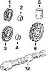
13 R104590 GEAR 1 X
14 .. WASHER NA X
15 R121195 CAP SCREW 4 X
16 R114130 STUD 4 X
17 M72490 WASHER 4 X
18 14H1090 NUT 4 X 3/8"
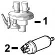
19 RE48606 FUEL PUMP 1 X
20 RE501198 FUEL PUMP 1 X (A) (DENSO) (ALSO ORDER R112128 AND (2)
19M8826)
21 .. FUEL LINE NA X
22 .. ELBOW FITTING NA X
23 .. O-RING NA X
24 R67364 ELBOW FITTING 1 X
25 RE63650 ANEROID LINE 1 X
26 AR87636 TEE FITTING 1 X
27 R67264 PACKING 1 X
28 RE52262 OIL LINE 1 X
29 19H1731 CAP SCREW 1 X
(A) SEE YOUR AUTHORIZED PUMP REPAIR STATION FOR PARTS NOT LISTED.
CONSULTEZ VOTRE REPARATEUR DE POMPE AGREE POUR LES PIECES NON CATALOGUES
NICHT GEZEIGTE TEILE VON PUMPENWERKSTAT BEZIEHEN
PER LE PARTI NON ELENCATE, RIVOLGETEVI AL CENTRO AUTORIZZATO DI RIPARAZ IONE POMPA.
CONSULTE CON SU ESTACION AUTORIZADA RE PEPARACIONES DE BOMBA.
RAADGOER MED EN AUTORISERAD PUMPSERVICVERKSTAD BETRAEFFANDE EJ UPPTAGNA
KEY PART NO. PART NAME QTY SERIAL NO. F F F REMARKS
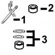
1 R60914 SET SCREW 1 X
2 R53918 PACKING 1 X
3 T31556 NUT 1 X
4 R68715 PIN 1 X
5 AR89339 SEAL 1 X
6 AR89578 LEVER 1 X
7 24M7054 WASHER 1 X 6.400 X 12 X 1.600 MM
8 T24229 LOCK WASHER 2 X
9 R68716 NUT 1 X
10 R129240 LEVER 1 X (A)
R504886 LEVER 1 XXXXXX- X (A)
11 19M8826 SCREW 2 X M6 X 16
12 R53976 SCREW 1 X (B)
13 24H1287 WASHER 1 X (B) 9/32" X 5/8" X 0.065"
14 RE54741 LEVER 1 X (C)
15 R68438 RETAINER 1 X
16 R53955 O-RING 1 X
(A) THROTTLE (TWO HOLES AT TOP) (B) NOT INCLUDED (C) SHUT-OFF
MANETTE DES GAZ NON INCLUS ROBINET D’ARRET
DROSSELKLAPPE NICHT MIT ABSCHALTUNG
ACCELERATORE NON COMPRESO RUBINETTO D’ARRESTO
ACELERADOR NO FORMA PARTE GRIFO DECIERRE
GASREGLAGE INGAAR INTE AVSTAENGING
KEY PART NO. PART NAME QTY SERIAL NO. F F F REMARKS
1 AR81847 SEAL 1 X
2 AR98286 LEVER 1 X
3 R64969 SCREW 2 X
4 R64926 LOCK WASHER 2 X
5 R112128 LEVER 1 X (A)
6 19M8826 SCREW 2 X
7 R64968 SHAFT KEY 1 X 3 X 13 MM
8 19H2036 CAP SCREW 1 X
9 24H1287 WASHER 1 X
10 RE33274 LEVER 1 X (B)
11 R64995 RETAINER 1 X
12 R73879 SPRING 1 X
13 R64997 O-RING 1 X
14 R73873 LOCK NUT 1 X
15 R73878 SET SCREW 1 X
(A) THROTTLE (TWO HOLES AT TOP) (B) SHUT-OFF
MANETTE DES GAZ ROBINET D’ARRET
DROSSELKLAPPE ABSCHALTUNG
ACCELERATORE RUBINETTO D’ARRESTO
ACELERADOR GRIFO DECIERRE
GASREGLAGE AUSTAEGING
 English
 Espaol
 Franais
 阿拉伯
阿拉伯 中文(简)
中文(简) Deutsch
 Italiano
 Português
 日本
日本 韩国
韩国 български
 hrvatski
 esky
esky Dansk
Dansk Nederlands
 suomi
suomi Ελληνικ
 印度
印度 norsk
norsk Polski
 Roman
Roman русский
 Svenska