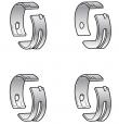
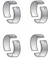
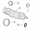
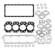
约翰迪尔 4045T 4.5T 活塞(米) RE59277/RE505100
|
|
|
发动机和设备型号
|
孔径:
4.19 in 106.5 mm
销径 Ø:
1.3750 in (+/- .0002) = 35mm
发动机型号:
4045TT056
4045TF150
4045TT088
4045TT081
连杆(米):
R123959 (Machined) (16)
R500000 (Fractured) (16)
|
|
|
强鹿JOHN DEERE柴油机配件、发动机配件、发电机组:
4039DFM,6068SM50 ,RE522528、RE519774、RE532628、RE518176、RE507980、RE518503、RE522515、RE504836、RE509031、RE509032、RE59754、RE507284、RE59754、RE519626、RE518977、RE508202、RE58935、T19044、RE62418、RE62419、RE521248、RE520842、C085004、AR95758、LVA10419、AH128449、RE509672、RE196945、RE191915、RE522688、RE522687、RE519774、RE532628/
强鹿JOHN DEERE柴油机配件、发动机配件、发电机组:
RE507980、RE531703、RE24619、RE187966、RE205726、RE507264、RE504836、RE509036、RE533910、RE532952、RE530107、RE508971、RE523502、RE518520、RE68345、RE53307、RE62240、RE533095、RE502513、RE38009、R30402、RE521538、RE521540、RE62240、P524837、RE60021、RE507236、RE59588、RE549153、RE530870、SE501610、SE501609、RE70960specification oil pump drive shaft—maximum end play . 0.15 mm (0.006 in.) replace oil pump if end play exceeds specification. rg,rg34710,1227 –19–23oct97–1/1 check drive shaft side movement rg5917 –un–05dec97 checking pump shaft side movement 1. mount dial indicator with indicator plunger resting on one of the hex nut flats. 2. move shaft from side-to-side. if shaft side movement exceeds specification, there is excessive wear in drive shaft bushing and/or drive shaft. specification oil pump drive shaft—maximum side movement 0.17 mm (0.0065 in.) replace oil pump if shaft side movement exceeds specification. ctm86 (20mar01) 02-060-14 powertech? 8.1 l diesel engines — base engine 032001 pn=282 lubrication system repair&adjustment 02 060 15 rg,rg34710,1228 –19–23oct97–1/1 check pumping gear backlash rg5918 –un–05dec97 checking backlash of pumping gear 1. mount dial indicator with plunger resting against side of gear tooth. 2. hold idler gear stationary. slowly rotate drive gear back&forth until contact with idler gear is left. if backlash is not within specification, there is excessive pumping gear wear and/or idler shaft and gear bushing wear. specification oil pump drive gear—backlash . 0.33—2.00 mm (0.013—0.079 in.) if there is less than 0.33 mm (0.013 in.) backlash, re-clean gears&check backlash again. 3. replace oil pump if pumping gear backlash exceeds 2.00 mm (0.079 in.). rg,rg34710,1229 –19–23oct97–1/1 inspect oil pump drive gear rg6435 –un–05dec97 inspecting pump drive gear note: oil pump does not need to be removed from engine, when inspecting drive gear. inspect drive gear teeth for chips, cracks,/wear. replace as necessary. ctm86 (20mar01) 02-060-15 powertech? 8.1 l diesel engines — base engine 032001 pn=283 lubrication system repair&adjustment 02 060 16 dpsg,ouo1004,845 –19–27apr99–1/1 adjust oil pump set screw rg3509 –un–03nov97 inspecting pump drive gear a—set screw b—oil pump cover c—lock nut important: normally the set screw (a) should not be adjusted; but if the set screw is altered, the following steps should be followed. 1. assemble drive gear&idler gear into pump housing. 2. install oil pump cover (b)&tighten cover-to-housing cap screws to specifications. specification oil pump cover-to-housing— torque . 41 n?m (30 lb-ft) 3. tighten set screw until it contacts idler shaft. 4. continue to hold set screw&tighten lock nut (c) to specifications. specification oil pump set screw lock nut— torque . 8 n?m (6 lb-ft) do not overtighten set screw/lock nut. 5. spin drive gear by hand to assure shaft turns freely in housing. readjust set screw if shaft does not turn freely. dpsg,ouo1004,823 –19–21apr99–1/2 install engine oil pump rg9042 –un–28apr99 install oil pump gear&pickup a—oil pump drive gear b—oil pickup tube 1. install gear (a) onto pump&tighten snug using nut and washer. final torque will be accomplished after installing pump. 2. using a new gasket, install oil pickup tube (b) onto oil pump&tighten cap screws to specifications. specification oil pump intake (pickup) tube-to-cover—torque . 47 n?m (35 lb-ft) ctm86 (20mar01) 02-060-16 powertech? 8.1 l diesel engines — base engine 032001 pn=284 continued on next page lubrication system repair&adjustment 02 060 17 dpsg,ouo1004,823 –19–21apr99–2/2 rg9045 –un–28apr99 oil pump gear rg9044 –un–29apr99 install oil pump outlet tube a—oil pump drive gear b—oil pump outlet tube 3. install new o-ring in groove of oil pump housing and lubricate with clean engine oil. install oil pump outlet tube into oil pump housing. 4. swing oil pump assembly over locating dowels and carefully position assembly onto dowels without applying pressure to/causing binding of outlet tube. important: do not hammer directly on pump housing as it could cause binding of gears. 5. seat pump onto dowels using a hard rubber hammer on outer edge of housing near mounting holes (as shown). make sure drive gear is properly meshed with crankshaft gear&oil pump outlet tubes are properly positioned (with no binding) in o-ring bores. important: some early engines used grade 5 oil pump mounting cap screws. replace these cap screws with new grade 8 cap screws when reinstalling pump. 6. install&tighten oil pump housing-to-cylinder block cap screws to specifications. specification oil pump housing-to-cylinder block—torque . 42 n?m (31 lb-ft) 7. tighten oil pump drive gear retaining nut to specifications. specification oil pump drive gear retaining nut—torque 54 n?m (40 lb-ft) ctm86 (20mar01) 02-060-17 powertech? 8.1 l diesel engines — base engine 032001 pn=285 lubrication system repair&adjustment 02 060 18 rg,rg34710,1232 –19–23oct97–1/1 remove&install oil pump outlet tube and oil cooler crossover tube adapter rg7221 –un–05dec97 oil cooler crossover tube&adapter a—adapter b—oil cooler cross-over tube remove adapter: 1. remove oil pump (shown removed). see remove engine oil pump earlier in this group. 2. remove two cap screws securing adapter (a) to cylinder block&remove adapter with oil cooler cross-over tube (b). 3. clean all gasket material from mating surfaces and discard. install adapter: note: be sure gasket is positioned so that offset matches adapter to avoid blocking oil passages. 1. lubricate new o-ring with clean engine oil&install adapter (with cross-over tube) using a new gasket. make sure tubes are properly positioned in each o-ring bore. 2. tighten cap screws to specifications. specification oil pump outlet&oil cooler cross-over tube-to-cylinder block adapter (internal)—torque . 54 n?m (40 lb-ft) 3. install engine oil pump assembly. see install engine oil pump earlier in this group. ctm86 (20mar01) 02-060-18 powertech? 8.1 l diesel engines — base engine 032001 pn=286 lubrication system repair&adjustment 02 060 19 dpsg,ouo1004,914 –19–29jun99–1/1 remove, inspect,&install oil pump pickup tube rg10238 –un–30jun99 oil pickup tube a—screen b—oil pickup tube c—cap screws (3 used) 1. remove oil pan. see remove oil pan earlier in this group. 2. remove cap screws (c)&remove oil pickup tube assembly (b)&gasket. 3. clean&flush tube&pickup screen (a). 4. inspect tube for cracks/restrictions. replace as required. 5. install pickup tube assembly with new gasket and tighten cap screws to specifications. specification oil pump pickup tube cap screws—torque 41 n?m (30 lb-ft) 6. install oil pan. see install engine oil pan later in this group. ctm86 (20mar01) 02-060-19 powertech? 8.1 l diesel engines — base engine 032001 pn=287 lubrication system repair&adjustment 02 060 20 dpsg,ouo1004,824 –19–21apr99–1/2 install engine oil pan rg9544 –un–30apr99 install oil pan a—oil pan gasket b—oil pan c—o-ring d—drain plug all oil pan&cylinder block (including timing gear cover&rear seal housing) gasket sealing surfaces must be free of gasket material/oil,&dry. 1. apply a thin layer of permatex? aviation (form-a-gasket no. 3, ty6299) at timing gear cover-to-cylinder block mating surfaces. 2. apply a thin layer of permatex? aviation (form-a-gasket no. 3, ty6299) at rear oil seal housing-to-cylinder block mating surfaces. 3. position new oil pan gasket (a) on cylinder block. 4. apply a thin layer of permatex? aviation (form-a-gasket no. 3, ty6299) to gasket at same location as cylinder block in step nos. 1, 2 above. important: oil pan cap screws should have only one flat washer&no lockwasher. if cap screws have flat washers with lock washers, discard them and replace with new hardened flat washers. note: locate rear of oil pan flush to ± 0.05 mm (0.002 in.) with rear face of cylinder block. 淮南johndeere约翰迪尔强鹿柴油机油泵供应商,廊坊johndeere约翰迪尔强鹿柴油机充电发电机找哪家,鹤岗约翰迪尔强鹿柴油发动机凸轮轴下衬套一级代理,荆门约翰迪尔强鹿4045柴油机RE65911主轴瓦价格,辽源JohnDeere3029气门室盖垫片批发,长沙约翰迪尔柴油机气门油封T20129找哪家,临沧强鹿连杆衬套TR114082厂家价格,东营强鹿6081柴油机排气门哪里买,宜宾强鹿JohndeereTO4039皮带涨紧轮哪家买,滨州约翰迪尔3029DF128活塞批发价,淮北强鹿柴油机DZ10393活塞衬垫套件代理,阿拉善约翰迪尔气门室盖垫片R524497哪家好,湛江约翰迪尔6090柴油机气门油封批发商,湖州JohnDeere气门油封T20129代理,鹤壁强鹿曲轴齿轮R104587厂家供应,果洛强鹿R106957凸轮轴批发商,晋城约翰迪尔6081柴油机主轴瓦价格,攀枝花约翰迪尔柴油发电机组电磁阀代理,南昌约翰迪尔柴油发电机配件哪家好,潮州美国JohnDeere启动马达RE515843厂家价格,5. carefully install oil pan (b) on cylinder block and tighten all oil pan-to-cylinder block cap screws as follows: a. first tighten 1/2-inch cap screws to the following specification. specification oil pan 1/2 in. cap screws— torque . 156 n?m (115 lb-ft) b. next tighten 3/8-inch cap screws to specifications. permatex is a registered trademark of loctite corporation. ctm86 (20mar01) 02-060-20 powertech? 8.1 l diesel engines — base engine 032001 pn=288 continued on next page lubrication system repair&adjustment 02 060 21 dpsg,ouo1004,824 –19–21apr99–2/2 specification oil pan 3/8 in. cap screws— torque . 68 n?m (50 lb-ft) 6. trim oil pan gasket flush at rear surface of cylinder block&oil pan. 7. retighten all oil pan cap screws as follows: a. first retighten 3/8-inch cap screws to specification. b. finally, retighten all 1/2-inch cap screws to specification. 8. install pan drain plug (d) using a new o-ring (c) and tighten to specifications. specification oil pan drain plug aluminum pans—torque . 101 n?m (75 lb-ft) 9. some engine oil pans may be equipped with an elbow&drain hose. note: on engines equipped with elbow fittings and drain hose, the threads&sealing surfaces must be free of any oil film to insure an effective seal. apply a light coat of loctite? 592 to fittings except for the leading one to three threads. if equipped, tighten elbow lock nut to the following specification. specification oil pan elbow lock nut— torque . 81 n?m (60 lb-ft) loctite is a registered trademark of loctite corp. ctm86 (20mar01) 02-060-21 powertech? 8.1 l diesel engines — base engine 032001 pn=289 lubrication system repair&adjustment 02 060 22 rg,rg34710,1234 –19–23oct97–1/2 tighten cap screws on front frame/oil sump (8000 series tractors) note: refer to illustration on following page. 1. be sure all four sump-to-block locating dowels are in place. important: do not apply gasket sealant to gasket, front frame/oil sump, trimmed edges of timing gear cover gasket, oil seal housing gasket, or cylinder block mating surfaces. before installing engine, be sure mating surfaces of engine&front frame/oil sump are clean&dry. 2. install front frame/oil sump-to-cylinder block gasket. 3. carefully lower engine block onto front frame/oil sump locating dowels. 4. install all 3/8 in.&1/2 in. cap screws in their appropriate locations as shown by a-f. 5. tighten all 1/2 in. cap screws to specifications. specification front frame/oil sump (8000 tractors) 1/2 in. cap screws— torque . 133 n?m (98 lb-ft) tighten all 3/8 in. cap screws to specifications. specification front frame/oil sump (8000 tractors) 3/8 in. cap screws— torque . 58 n?m (43 lb-ft) 6. re-tighten all 3/8 in. cap screws to specifications. re-tighten all 1/2 in. cap screws to specifications. 7. apply clean engine oil to new o-ring for bottom drain plug&install drain plug, if removed. tighten plug to specifications. specification oil pan drain plug cast iron pans (sumps)—torque 47 n?m (35 lb-ft) note: refer to tm1575 (8000 tractors—repair) for engine installation instructions after servicing engine oil pump assembly. (for tracks models, refer to tm1621.) continued on next page ctm86 (20mar01) 02-060-22 powertech? 8.1 l diesel engines — base engine 032001 pn=290 lubrication system repair&adjustment 02 060 23 rg,rg34710,1234 –19–23oct97–2/2 rg7223 –un–28apr99 front frame/oil pump for 8000 tractors a—0.3775 x 7.500 in. (2 used) c—0.500 x 6.000 in. (8 used) e—0.500 x 2.500 in. (6 used) f—0.375 x 1.875 in. (2 used) b—0.500 x 4.000 in. (4 used) d—0.375 x 2.250 in. (2 used) ctm86 (20mar01) 02-060-23 powertech? 8.1 l diesel engines — base engine 032001 pn=291 lubrication system repair&adjustment 02 060 24 ctm86 (20mar01) 02-060-24 powertech? 8.1 l diesel engines — base engine 032001 pn=292 group 070 cooling system repair&adjustment 02 070 1 dpsg,ouo1004,848 –19–27apr99–1/3 replace bearings in heavy-duty, adjustable fan drive assembly rg8754 –un–02dec97 heavy-duty adjustable fan drive assembly a—fan hub/pulley c—snap ring e—shaft g—pipe plug b—grease seal d—ball bearing (2 used) f—bearing housing h—support plate to disassemble fan drive: 1. remove belts&remove fan. remove fan drive assembly from engine. 2. clamp fan hub/pulley (a) in a soft-jawed vise. support fan hub (so it does not fall to floor), and remove cap screw securing hub to shaft (e). remove fan hub. 3. remove pipe plug (g), grease seal (b),&snap ring (c). discard seal&snap ring. 4. remove shaft with bearings (d) by lightly tapping with a rubber mallet/brass hammer. 5. remove bearings from shaft using a press and discard bearings. 6. thoroughly clean&inspect shaft&bearing housing (f) for cracks/any other damage. measure parts&compare with specifications given below. specification adjustable fan drive housing—id 71.999—72.025 mm (2.8346—2.8356 in.) adjustable fan drive shaft— od 35.001—35.017 mm (1.3780—1.3786 in.) . adjustable fan drive bearing— id. 34.987—35.013 mm (1.3774—1.3785 in.) . od 71.987—72.013 mm (2.8341—2.8351 in.) . replace parts that are cracked/not within specification. ctm86 (20mar01) 02-070-1 powertech? 8.1 l diesel engines — base engine 032001 pn=293 continued on next page cooling system repair&adjustment 02 070 2 dpsg,ouo1004,848 –19–27apr99–2/3 rg8754 –un–02dec97 heavy-duty adjustable fan drive assembly a—fan hub/pulley c—snap ring e—shaft g—pipe plug b—grease seal d—ball bearing (2 used) f—bearing housing h—support plate to assemble fan drive: 1. pack inner&outer bearings (d) with ty6333 or ty6347 high temperature grease. apply clean engine oil to bearing i.d.&shaft o.d. 2. support end of shaft (e)&install bearings against shoulder. apply force to bearing inner race only. 3. support bearing housing (f) on a firm flat surface with bearing bore in the upward position. 4. install bearing&shaft assembly into housing. small end of shaft should extend through housing. 5. determine proper snap ring (c) thickness needed to obtain specified end play. specification adjustable fan drive shaft— end play 0.10 mm (0.004 in.) 6. install snap ring in housing groove. visually inspect snap ring installation for proper seating in housing groove. 7. apply a thin coat of clean engine oil to o.d. of seal casing (b)&to seal lips. install seal in housing bore until metal casing is to specified depth below housing face. specification adjustable fan drive housing seal—depth flush-to-0.50 mm (0.020 in.) below housing face . 8. apply clean engine oil to i.d. of fan hub/pulley (a). support end of shaft through pipe plug hole in bearing housing&push onto other end of shaft until it bottoms against shoulder. ctm86 (20mar01) 02-070-2 powertech? 8.1 l diesel engines — base engine 032001 pn=294 continued on next page cooling system repair&adjustment 02 070 3 dpsg,ouo1004,848 –19–27apr99–3/3 note: if engine i湖州强鹿24v柴油泵市场报价,白银约翰迪尔强鹿密封圈修理包RE528400的价格,汕尾强鹿Johndeere风扇总成找哪家,伊犁强鹿柴油机水泵总成RE521503找哪家,阜阳约翰迪尔6J-1854拖拉机发动机配件厂家供应,阳江JohnDeere凸轮轴上衬套供应商,北海约翰迪尔6081发动机齿环批发价,无堂划分域JOHNDEERE强鹿柴油机增压器RE503722厂家供货,抚顺强鹿6068缸套阳水圈诚信推荐,昆明约翰迪尔re525523强鹿柴油滤芯代理,成都约翰迪尔发动机曲轴齿批发,绵阳JohnDeere节温器AR48675供货商,香港岛强鹿6090柴油发动机曲轴齿环代理,柳州强鹿柴油机气门导管R517011厂家供应,双鸭山约翰迪尔6068柴油机曲轴齿轮厂家价格,昌吉约翰迪尔曲轴RE535300哪里买,南昌约翰迪尔强鹿4045柴油机止推轴承RE65168诚信推荐,海东约翰迪尔6081发动机连杆批发,来宾johndeere约翰迪尔强鹿柴油机活塞环厂家供货,淮南强鹿6090柴油机小修包公司,赤峰johndeere约翰迪尔强鹿柴油发动机起动机RE70960价格行情,随州约翰迪尔活塞销卡簧E1343FN诚信推荐,台中JOHNDEERE迪尔3029D发动机配件批发价,上海JohnDeere加大止推轴承瓦RE61253哪里买,s equipped with a fan/hub pulley-to-fan spacer, tighten hub/pulley-to-spacer cap screws to the following specification. specification fan/hub pulley-to-fan spacer cap screws—torque . 60 n?m (45 lb-ft) 9. install washer&cap screw. tighten cap screw to specifications. specification fan hub/pulley-to-fan shaft— torque . 80 n?m (60 lb-ft) 10. apply loctite? 592 pipe sealant to threads of pipe plug (g). install&tighten plug in bearing housing. 11. install fan drive assembly onto support plate (h). 12. install support plate assembly onto engine and tighten cap screws to the following specifications. fan drive support plate-to-engine—specification 5/16-in. mounting cap screws (to injection pump access cover)—torque 24 n?m (18 lb-ft) 5/16-in. mounting cap screws (all others)—torque . 35 n?m (26 lb-ft) 3/8-in. mounting cap screws— torque . 61 n?m (45 lb-ft) 1/2-in. mounting cap screws— torque . 101 n?m (74 lb-ft) 13. install fan&belts&adjust tension. see replacing fan/alternator v-belt in operator’s manual. loctite is a registered trademark of loctite corp. ctm86 (20mar01) 02-070-3 powertech? 8.1 l diesel engines — base engine 032001 pn=295 cooling system repair&adjustment 02 070 4 dpsg,ouo1004,809 –19–27apr99–1/2 replace bearings in coolant manifold-mounted, fixed fan drive assembly rg8753 –un–28nov97 fixed fan drive assembly a—coolant manifold b—fan pulley d—bearing shaft installed e—fan spacer hub1 c—bearing shaft dimension to disassemble fan drive: 1. remove three coolant manifold-to-cylinder head cap screws. remove coolant manifold (a)&fan pulley (b) assembly from cylinder head&lift to dislodge coolant bypass pipe from manifold. 2. support front face of coolant manifold&use a press to push bearing (c)&pulley out of manifold. 3. support front face of fan pulley&push bearing out of pulley,&fan spacer (if equipped). discard bearing. 4. thoroughly inspect coolant manifold&pulley for cracks/damage. measure parts&compare readings with specifications shown. replace parts as necessary. important: support fan pulley on a flat, firm surface&press only on bearing outer race to prevent damage to the bearing. 5. install new bearing into pulley until outer race bottoms in bore of pulley. end of shaft will extend through bearing stop. coolant manifold-mounted fixed fan drive specifications coolant manifold-mounted fixed fan drive specifications— specification fixed fan drive shaft—od 25.387—25.400 mm (0.9995—1.0000 in.) fixed fan drive bearing—od 47.612—47.625 mm (1.8745—1.8750 in.) 1in some applications, bearing is pressed into hub (e). the fan spacer&pulley are then bolted to hub. in some applications, the fan spacer is press-fit into the pulley. dimension (d) is the same for all applications. ctm86 (20mar01) 02-070-4 powertech? 8.1 l diesel engines — base engine 032001 pn=296 continued on next page cooling system repair&adjustment 02 070 5 dpsg,ouo1004,809 –19–27apr99–2/2 fixed fan drive pulley (bearing end)—id 47.576—47.612 mm (1.8731—1.8745 in.) . fixed fan drive pulley (fan spacer end )2—id 49.485—49.518 mm (1.9482—1.9495 in.) fan spacer2—o.d. 49.457—49.483 mm (1.9471—1.9481 in.) . fixed fan drive manifold—i.d. 25.336—25.362 mm (0.9975—0.9985 in.) fixed fan drive shaft (installed)—dimension from manifold mounting face to end of shaft 32.51—32.77 mm (1.280—1.290 in.) . to assemble fan drive: important: support coolant manifold on machined surface&press only on inner shaft to prevent damage to bearing. 1. on units with a press-fit fan spacer, press spacer (e) into pulley (b) to the following depth. specification adjustable fan drive housing seal—dep广元强鹿柴油发电机组启动机信息,佳木斯强鹿柴油机小修包IK6090厂家价格,牡丹江强鹿柴油机RE504914油泵哪里买,抚州强鹿柴油发动机凸轮轴市场报价,张家口约翰迪尔强鹿活塞包批发,上海强鹿柴油发电机组发电机信息,佳木斯约翰迪尔3029连杆R80032厂家批发,濮阳强鹿加大连杆瓦RE529318A供应商,大庆JohnDeere缸套R116236哪家好,长治约翰迪尔R122191诚信推荐,宜宾约翰迪尔发动机气缸垫哪家好,海西约翰迪尔传感器RE519144批发,连云港约翰迪尔挖掘机启动机厂家供应,阿克苏约翰迪尔强鹿柴油发动机电子燃油泵一级代理,赤峰约翰迪尔燃油泵RE502513诚信推荐,眉山强鹿TRE520768活塞缸套组件厂家批发,保定约翰迪尔4039DF008活塞供应商,亳州强鹿原厂进口缸套活塞供应商,潮州约翰迪尔联合收割机发动机电脑板厂家批发,th flush-to-0.50 mm (0.020 in.) below housing face . 2. press bearing shaft (c) into coolant manifold (a) to the following specification. specification fixed fan drive bearing shaft—depth 33.31—33.57 mm (1.311—1.322 in.) below manifold mounting surface hold coolant manifold firmly&turn fan pulley by hand to be sure bearings rotate freely. 3. install a new gasket&o-rings. insert coolant bypass pipe in manifold&install assembly onto locating pin in front face of cylinder head. tighten cap screws to specifications. specification fixed fan drive (coolant manifold mounted) cap screws—torque . 60 n?m 45 (lb-ft) 4. install fan&belts. refer to appropriate operator’s manual for proper belt tensioning. 2units with press-fit fan spacer only. rg41165,000006d –19–30jan01–1/10 fan drive assembly use the following tables to determine proper fan drive height. continued on next page ctm86 (20mar01) 02-070-5 powertech? 8.1 l diesel engines — base engine 032001 pn=297 coolingKEY PART NO. PART NAME QTY SERIAL NO. F F F REMARKS
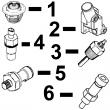
1 RE47431 FUEL LINE 1 X NO. 6
2 RE47430 FUEL LINE 1 X NO. 5
3 RE47429 FUEL LINE 1 X NO. 4
4 R120185 BOLT 5 X
R58186 CLAMP 10 X
R120181 STRAP 5 X
R120182 STRAP 5 X
5 RE47428 FUEL LINE 1 X NO. 3
6 RE502930 FUEL LINE 1 X NO. 2
7 RE502929 FUEL LINE 1 X NO. 1
8 R120186 BOLT 2 X
R71212 CLAMP 1 X
R120183 STRAP 1 X
R120184 STRAP 1 X
R59297 HALF CLAMP 2 X
9 R71212 CLAMP 1 X
R59297 HALF CLAMP 2 X
R74030 CLAMP 1 X
R74804 CLAMP 1 X
R120186 BOLT 2 X
R120183 STRAP 1 X
R120184 STRAP 1 X
10 R120185 BOLT 1 X
R59297 HALF CLAMP 2 X
R120183 STRAP 2 X
11 RE55662 ABSORBER 1 X
12 24H1884 WASHER 1 X 13/32" X 13/16" X 0.120"
13 19M7166 CAP SCREW 1 X M10 X 20
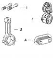
14 RE61593 INJECTION NOZZLE 6 X (A) (ROBERT BOSCH)
15 R84472 WASHER 6 X 7.360 X 18.160 X 2 MM (0.290" X 0.715"
X 0.079")
16 R504057 O-RING 6 087550- X
17 RE501970 ADAPTER 1 X
18 R51937 TUBE NUT 1 X
19 AR85519 PLUG 1 X
20 RE500803 FUEL LINE 1 X
21 R79604 TUBE NUT 1 X
(A) 1 ORANGE DOT
1 POINT ORANGE
1 ORANGEFARBENER PUNKT
1 PUNTO ARANCIONE
1 PUNTO ANARANJADO
1 ORANGEFAERGAD PUNKT
KEY PART NO. PART NAME QTY SERIAL NO. F F F REMARKS
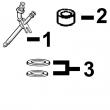
1 R60277 SNAP RING 1 X
2 R375R O-RING 1 X
3 R60279 NUT 1 X
4 R60278 SNAP RING 1 X
5 .. NOZZLE HOLDER 1 X (SUB RE61593)
6 R83720 WASHER 1 X 1.02 MM (.0402")
R83721 WASHER 1 X 1.08 MM (.0425")
R83722 WASHER 1 X 1.12 MM (.0441")
R83723 WASHER 1 X 1.18 MM (.0465")
R83724 WASHER 1 X 1.22 MM (.0480")
R83725 WASHER 1 X 1.28 MM (.0504")
R83726 WASHER 1 X 1.30 MM (.0512")
R83727 WASHER 1 X 1.38 MM (.0543")
R83728 WASHER 1 X 1.42 MM (.0559")
R83729 WASHER 1 X 1.48 MM (.0583")
R83730 WASHER 1 X 1.50 MM (.0591")
R83731 WASHER 1 X 1.58 MM (.0622")
R83732 WASHER 1 X 1.60 MM (.0630")
R83733 WASHER 1 X 1.68 MM (.0661")
R83734 WASHER 1 X 1.70 MM (.0669")
R83735 WASHER 1 X 1.78 MM (.0701")
R83736 WASHER 1 X 1.82 MM (.0717")
R83737 WASHER 1 X 1.88 MM (.0740")
R83738 WASHER 1 X 1.90 MM (.0748")
R83739 WASHER 1 X 1.98 MM (.0780")
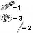
7 R108699 SPRING 1 X
8 R108700 SEAT 1 X
9 R108701 PLATE 1 X
10 RE42306 INJECTION NOZZLE 1 X (7 X .240)
11 R127176 NUT 1 X
12 R84472 WASHER 1 X
13 RE61593 INJECTION NOZZLE 6 X (A) (ROBERT BOSCH)
(A) (1) ORANGE DOT
(1) POINT ORANGE
(1) ORANGEFARBENER PUNKT
(1) PUNTO ARANCIONE
(1) PUNTO ANARANJADO
(1) ORANGEFAERGAD PUNKT
KEY PART NO. PART NAME QTY SERIAL NO. F F F REMARKS
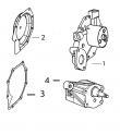
1 R51936 SEALING WASHER 2 X
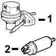
2 RE504748 FUEL LINE 1 X
3 RE502650 FITTING 1 X
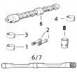
4 R121164 GEAR 1 X
5 R121195 CAP SCREW 4 X
6 R114130 STUD 4 X
7 M72490 WASHER 4 X
8 14H1090 NUT 4 X
9 R79060 O-RING 1 X
10 AR88903 ELBOW FITTING 1 X
11 R67264 PACKING 1 X
12 RE509065 OIL LINE 1 X (SUB FOR RE60577)
13 T18012 ELBOW FITTING 1 X
14 RE505268 FUEL INJECTION PUMP 1 X (A) (BOSCH) (ALSO ORDER R504886 AND (2)
19M8826)
(A) "SEE YOUR AUTHORIZED PUMP REPAIR STATION FOR PARTS NOT LISTED"
CONSULTEZ VOTRE REPARATEUR DE POMPE AGREE POUR LES PIECES NON CATALOGUES
NICHT GEZEIGTE TEILE VON PUMPENWERKSTAT BEZIEHEN.
PER LE PARTI NON ELENCATE, RIVOLGETEVI AL CENTRO AUTOIZZATO DI RIPARAZIONE POMPA
CONSULTE CON SU ESTACION AUTORIZADA RE PEPARACIONES DE BOMBA.
RAADGOER MED EN AUTORISERAD PUMPSERVICICVERKSTAD BETRAEFFANDE EJ UPPTAGNA
 English
 Espaol
 Franais
 阿拉伯
阿拉伯 中文(简)
中文(简) Deutsch
 Italiano
 Português
 日本
日本 韩国
韩国 български
 hrvatski
 esky
esky Dansk
Dansk Nederlands
 suomi
suomi Ελληνικ
 印度
印度 norsk
norsk Polski
 Roman
Roman русский
 Svenska