美国强鹿JOHN DEERE柴油发电机配件及发动机配件:
CD3029DF128、CD4039DF008、CD4045TF258、PE4045、CD6068TF158、CD6068TF258、CD6068HF158、CD6068HF258、CD6081HF001A、4045TFM75、CD6081HF001B、CD6125HF070A、CD6125HF070B、RG6125、6135H458。4045DFM70, 4045TFM75, 6068TFM75, 6068TFM76、4039DFM RE522528、RE519774、RE532628、RE518176、RE507980、RE518503、RE522515、RE504836、RE509031
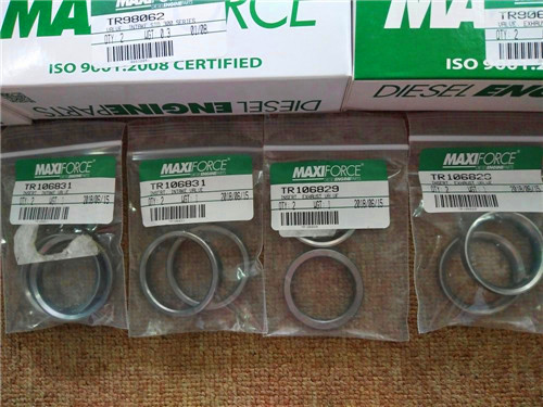
麦克福斯约翰迪尔发动机零配件
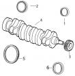
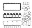
约迪尔 6081 高压缩活塞
|
|
|
发动机和设备型号
|
高压缩活塞
4801 4803
孔径:
4.56 in 116 mm
销径 Ø:
1.8742 in (+/- .0002) = 47 mm
发动机型号:
6081HDW08
6081HDW09
6081HDW13
6081HRW25
6081HRW31
6081HRW32
6081HRW33
6081HRW34
6081HRW41
6081HRW42
6081HRW43
6081HT002
6081HT008
6081HTJ05
6081HTJ06
6081HTJ07
6081HTJ08
6081HZ009
|
|
|
counterbore. 4. inspect liner support flange (c) for burrs. if burrs are present, use respective liner with lapping compound to remove burrs. 5. measure liner flange counterbore depth (a) in block (b) and flange thickness on liner. compare with specification given below. specification cylinder liner flange counterbore—depth in block 9.461—9.512 mm (0.3725—0.3745 in.) cylinder liner flange—thickness 9.525—9.575 mm (0.3750—0.3770 in.) 6. carefully inspect block for cracks/any other physical damage. if a cracked block is suspected, pressure-test the block. a procedure for pressure testing is outlined in fos (fundamentals of service) manual—engines. replace block if there is evidence of a crack or physical damage. ctm100 (20mar01) 02-030-41 powertech 10.5 l & 12.5 l diesel engines 032001 pn=181 cylinder block, liners, pistons,&rods 02 030 42 rg,rg34710,128 –19–03aug99–1/2 measure cylinder block rg8208 –un–21may98 measuring block top deck flatness refer to the appropriate groups for a more detailed description of the features being measured. compare measurements with specifications given below. 1. assemble&measure main&thrust bearing bores. compare measurements with specifications given below: specification main&thrust bearings— assembled id without bearings 133.097—133.123 mm (5.2400—5.2410 in.) . main bearing surface width 37.77—38.03 mm (1.487—1.497 in.) . thrust bearing surface width (no. 5 main) 37.51—38.29 mm (1.476—1.507 in.) overall thrust bearing cap width 43.25—43.75 mm (1.703—1.722 in.) if any main/thrust bearing cap assembled id is not within specification, blank (generic) bearing caps are available&must be line bored to specification by a qualified machine shop. (see measure assembled id of main bearing caps in group 040.) 2. measure cylinder block top deck flatness using d05012st precision straightedge&feeler gauge. resurface as required. specification cylinder block top deck surface finish—surface finish (surface mill only) . 3.2 micrometers (125 micro-in.) max. wave height 0.008 micrometers (0.0002 micro-in.) . max. wave depth . 2.0 micrometers (79 micro-in.) main bearing bore centerline-to-top deck— minimum distance 429.92—430.07 mm (16.926—16.932 in.) . continued on next page ctm100 (20mar01) 02-030-42 powertech 10.5 l & 12.5 l diesel engines 032001 pn=182 cylinder block, liners, pistons,&rods 02 030 43 rg,rg34710,128 –19–03aug99–2/2 important: the centerline of the main bearing bore-to-top deck of cylinder block must be 429.92–430.07 mm (16.926– 16.932 in.). if not, replace cylinder block. 3. measure cylinder liner bores in block&compare to the following specifications. cylinder block bore for seating liner—specification liner flange counterbore—id 153.57—153.77 mm (6.046—6.054 in.) upper block bore for seating liner—id 145.845—145.895 mm (5.7419—5.7439 in.) lower block bore for seating liner—id 140.465—140.515 mm (5.5301—5.5321 in.) ctm100 (20mar01) 02-030-43 powertech 10.5 l & 12.5 l diesel engines 032001 pn=183 cylinder block, liners, pistons,&rods 02 030 44 rg,rg34710,129 –19–30sep97–1/1 recheck cylinder liner standout (height above block) rg7142 –un–05dec97 liner counterbore depth rg8329 –un–21may98 measuring liner standout a—liner flange counterbore depth b—block c—liner support flange note: if a new liner assembly is being installed in a new or used cylinder block, liner standout must be checked. be sure liner bore in cylinder block (b)&top deck of cylinder block are clean. 1. install liners without o-rings&square packing. secure with cap screws&washers, as outlined earlier in this group. (see remove pistons and connecting rods in this group.) note: install liner with the identifying mark toward the front of the engine. rotate 90° if pits/erosion exceed limits outlined during liner inspection. 2. measure liner standout. (see measure cylinder liner standout earlier in this group.) specification cylinder liner standout—height above block 0.030—0.117 mm (0.0012—0.0046 in.) if liner standout is above specification, recheck liner support flange (c) for possible remaining burrs or incorrect counterbore depth (a) in block. if burrs are present, use respective liner&lapping compound to remove burr. completely clean cylinder liner bore after lapping. important: one liner shim only may be installed under any given liner flange. if liner standout is below specifications, remove liner and install shim as needed to bring liner standout to within specification. specification cylinder liner shims available— thickness 0.05 mm (0.002 in.) thickness 0.10 mm (0.004 in.) ctm100 (20mar01) 02-030-44 powertech 10.5 l & 12.5 l diesel engines 032001 pn=184 cylinder block, liners, pistons,&rods 02 030 45 rg,rg34710,130 –19–01nov00–1/2 install cylinder liner o-rings&packings rg3826 –un–04dec97 liner o-rings&packing a—black viton o-ring b—red silicone o-ring c—cylinder block note: piston&liner sets differ between engines. do not mix piston&liner sets. see parts catalog for correct applications. important: do not use oil on cylinder liner packing/o-rings. oil can cause the red packing to swell, which squeezes liner&could possibly cause a scored piston. 1. pour ar54749 soap lubricant into a suitable container. 2. dip new packings&o-rings in soap before installation. do not leave packings/o-rings in soap to soak. 3. install the black viton o-ring (a) in the lower o-ring groove of the cylinder block (c). 4. install the red silicone o-ring (b) in the upper o-ring groove of the cylinder block. rg,rg34710,130 –19–01nov00–2/2 rg3827 –un–04dec97 a—neoprene square packing install square packing on liner b—cylinder liner 5. turn cylinder liner (b) upside-down&install the neoprene square packing (a) over outside of liner. 6. slide packing down firmly against second shoulder on the liner. note: make sure the packing is not twisted. 7. coat the liner packings, sealing area of the cylinder liner,&cylinder block o-rings with liquid soap. ctm100 (20mar01) 02-030-45 powertech 10.5 l & 12.5 l diesel engines 032001 pn=185 cylinder block, liners, pistons,&rods 02 030 46 rg,rg34710,131 –19–01nov00–1/2 install cylinder liners rg2772 –un–04dec97 installing liner note: piston&liner sets differ between engines. do not mix piston&liner sets. see parts catalog for correct applications. important: install cylinder liner朔州强鹿排气门R93311批发,商丘约翰迪尔强鹿连杆螺栓信息,濮阳约翰迪尔5-954拖拉机发动机配件找哪家,南充约翰迪尔4045柴油机空气加热器找哪家,怀化约翰迪尔温度传感器RE51774代理,潍坊强鹿电热塞el502079批发商,阜新强鹿进气门R84618价格行情,三亚强鹿柴油发电机组止推片批发价,赣州约翰迪尔1204拖拉机拖拉机发动机配件多少钱,安阳强鹿喷油器O型圈RE528349价格,忻州约翰迪尔5-850拖拉机发动机配件供货商,崇左强鹿RE65908连杆瓦代理商,通辽强鹿柴油滤芯AR86745供货商,三亚johndeere约翰迪尔强鹿柴油机机油冷却器代理商, into same cylinder block bore as removed. do not scuff the packing across the upper bore. when liner ods are pitted/eroded and are under one-half the liner thickness, rotate liners 90° from their removed position. rotate the pitted section of the liner toward either the front/rear of the engine. if liners are not pitted/eroded, rotation will not be necessary. install liners with the identifying mark (stamped on flange), toward the front of the engine. 1. carefully place the cylinder liner, with packing installed, into the cylinder block bore. note: a resistance will be felt when cylinder liner is aligned in pilot bore. 2. using only the pressure of both palms, the cylinder liner should drop to a point nearly flush at the upper flange of the cylinder liner&cylinder block. continued on next page ctm100 (20mar01) 02-030-46 powertech 10.5 l & 12.5 l diesel engines 032001 pn=186 cylinder block, liners, pistons,&rods 02 030 47 rg,rg34710,131 –19–01nov00–2/2 t48319 –un–23feb89 seating liner rg10342 –un–10sep99 jdg1145 liner service set a—slide hammer b—liner service set note: cylinder liner will protrude over top of cylinder block more than normal due to uncompressed packings&o-rings. 3. finish seating cylinder liners using a clean hardwood block&hammer as shown in top figure/by using jdg1145 liner service set (b)&a 2.27 kg (5 lb) slide hammer (a) shown in lower figure. using either method, apply only enough force as necessary to seat liners. important: if you suspect that a packing may have sheared/displaced during liner installation, remove liner&packing assembly. if no damage is found, check packing&o-rings for proper position. resoap packings&reinstall liner assembly. 4. hold liners in place with large flat washers&cap screws. turn cap screws snug, but do not tighten. 5. clean cylinder liner bores with waterless hand cleaner after installation. wipe dry with clean towels. 6. apply clean engine oil to liner bores immediately to prevent corrosion. ctm100 (20mar01) 02-030-47 powertech 10.5 l & 12.5 l diesel engines 032001 pn=187 cylinder block, liners, pistons,&rods 02 030 48 rg,rg34710,132 –19–01nov00–1/2 assemble pistons&connecting rods rg8401 –un–09dec97 6125 piston crown&skirt rg8400a –un–22may98 assembling piston&rod a—piston steel crown (6125 engine) b—piston skirt (6125 engine) c—connecting rod d—compression rings (2 used) e—oil control ring note: piston&liner sets differ between engines. do not mix piston&liner sets. see parts catalog for correct applications. important: pistons must be installed on same connecting rods from which they were removed&new piston pin snap rings must be used. if a new piston&liner assembly is to be installed, do not remove piston from liner. push piston out of liner bottom only far enough to install piston pin. 1. on 6125 engines, assemble piston crown (a)&skirt (b) so that connecting rod pin bushings are aligned. 2. lubricate piston pin&bushings with clean engine oil. note: pistons are symmetrical; new pistons can be installed either way. if pistons are being reused, align front reference mark made during disassembly with front of connecting rod. 3. install piston pin through piston&connecting rod (c). 4. install new piston pin snap rings in grooves. make certain snap rings have completely expanded in grooves of piston. sharp edge of snap ring must face toward outside of piston. continued on next page ctm100 (20mar01) 02-030-48 powertech 10.5 l & 12.5 l diesel engines 032001 pn=188 cylinder block, liners, pistons,&rods 02 030 49 rg,rg34710,132 –19–01nov00–2/2 note: keystone compression ring with one “pip” mark goes in top piston ring groove&keystone ring with two “pip” marks goes in second ring groove of piston. “pip” mark(s) must face top of piston. important: pistons&ring sets differ between engines. piston part numbers are marked on top of pistons for identification. ensure correct size rings are installed on appropriate pistons. do not intermix rings. early engines engine piston compression oil control ring size ring size 10.5 l re52836, 4 mm 4.8 mm re504801 12.5 l re66125 4 mm 4.8 mm later engines 10.5 l re504343 3 mm 4 mm 12.5 l re503969, 3 mm 4 mm re505901 5. use the jdg967 ring expander to install compression rings (d)&oil control ring with expander ring (e). rg,rg34710,133 –19–02aug99–1/6 install pistons&connecting rods rg10300 –un–27aug99 connecting rods a—tongue-and-groove rod (early engines) b—precision joint? rod (later engines) important: replace rods with the same type. do not mix tongue-and-groove with precision joint? rods in the same engine. see parts catalog for recommendations. earlier engines have the traditional tongue-and-groove between the connecting rod&cap (a). later engines have the precision joint? rod&cap (b). both types of rods provide a strong joint. installation is similar, with differences noted, including different torque specifications for cap screws. precision joint is a trademark of deere & company ctm100 (20mar01) 02-030-49 powertech 10.5 l & 12.5 l diesel engines 032001 pn=189 continued on next page cylinder block, liners, pistons,&rods 02 030 50 rg,rg34710,133 –19–02aug99–2/6 rgr31127 –un–11dec97 staggering piston ring gaps a—piston head b—top compression ring gap c—oil control ring gap d—expander ring gap e—bottom compression ring gap f—front of engine 1. stagger ring gaps on pistons as shown. rg,rg34710,133 –19–02aug99–3/6 rg8404 –un–09dec97 compressing piston rings g—jdg1017 ring compres 2. coat pistons, liners,&inside of jdg1017 piston ring compres (g) with clean engine oil. 3. lay piston rod assembly on piston’s top&compress rings with compres . squeeze handles together and install pin to full depth to secure. 4. lubricate rod bearing half&install onto rod with notches on bearing seated with notch in rod. continued on next page ctm100 (20mar01) 02-030-50 powertech 10.5 l & 12.5 l diesel engines 032001 pn=190 cylinder block, liners, pistons,&rods 02 030 51 rg,rg34710,133 –19–02aug99–4/6 rg8366 –un–21may98 installing piston&rod assembly 5. carefully place ring compres with piston&rod over liner. important: be sure crankshaft journals&liner walls are not damaged when installing piston&rod liner. note: be sure the word “front” on connecting rod faces toward the front of the engine. 6. with piston centered in ring compres &rings staggered correctly, push piston into liner. rg,rg34710,133 –19–02aug99–5/6 rg8409b –un–09dec97 installing rod caps rg8396 –un–21may98 tightening rod caps a—crankshaft rod journals b—bearing inserts 7. apply clean engine oil to bearing inserts (b) and crankshaft rod journals (a). important: on precision joint? rods, make sure cap is properly aligned on rod with interlocking surfaces sealing tightly and edges aligned. do not reverse cap on rod. match pads on side of rod&cap. when installing caps, make sure stamped numbers on rod&cap are positioned on the same side. never use connecting rod cap screws more than once for final engine assembly. once rod cap screws have been tightened to final torque-turn specifications, they cannot be reused for final assembly. 8. install connecting rod caps. precision joint is a trademark of deere & company ctm100 (20mar01) 02-030-51 powertech 10.5 l & 12.5 l diesel engines 032001 pn=191 continued on next page cylinder block, liners, pistons,&rods 02 030 52 rg,rg34710,133 –19–02aug99–6/6 rg4375 –un–05dec97 tightening rod cap screws a—blind-hole cap screw 9. dip new cap screws&washers in clean engine oil. make sure of cap screws have oil on them also. important: do not use pneumatic wrenches to install connecting rod cap screws. doing so may damage threads. use speed-handle wrench instead. 10. on tongue-and-groove connecting rods: initially, tighten blind-hole cap screw (a) to specifications. next, tighten the other cap screw. feel rod-to-cap joint to check for proper alignment. specification tongue-and-groove connecting rod cap screw—initial torque . 27 n?m (20 lb-ft) second, tighten all cap screws to the following specifications, then torque-turn all cap screws 90—100°. specification tongue-and-groove connecting rod cap screw—final torque 75 n?m (55 lb-ft) plus 90—100° turn clockwise . (see torque-turn connecting rod cap screws, next in this group.) 11. on precision joint? connecting rods: initially, tighten cap screw closest to piston end to specifications. next, tighten the other cap screw. feel rod-to-cap joint to check for proper alignment. specification precision joint? connecting rod cap screw—torque 140 n?m (103 lb-ft) plus 90—100° turn clockwise (see torque-turn connecting rod cap screws, next in this group.) precision joint is a trademark of deere & company ctm100 (20mar01) 02-030-52 powertech 10.5 l & 12.5 l diesel engines 032001 pn=192 cylinder block, liners, pistons,&rods 02 030 53 rg,rg34710,134 –19–03aug99–1/2 torque-turn connecting rod cap screws rg9102 –un–27mar98 torque-turn rod cap screws a—wrench parallel to centerline of engine crankshaft axis b—wrench perpendicular to centerline of engine crankshaft axis using engine axis method to torque-turn connecting rod cap screws 1. after tightening cap screws to torque values, mark connecting rod cap&socket. 2. position handle of wrench parallel to centerline of engine crankshaft axis (a). 3. tighten 1/4 turn (90—100°) clockwise until handle of wrench is perpendicular to centerline of engine crankshaft axis (b) as shown. rg,rg34710,134 –19–03aug99–2/2 rg5698 –un–05dec97 jt05993 torque angle gauge using jt05993 torque angle gauge to torque-turn connecting rod cap screws after tightening cap screws to torque values, follow directions provided with gauge&torque-turn each cap screw 90°—100°. ctm100 (20mar01) 02-030-53 powertech 10.5 l & 12.5 l diesel engines 032001 pn=193 cylinder block, liners, pistons,&rods 02 030 54 rg,rg34710,135 –19–30sep97–1/1 check engine rotation for excessive tightness 1. rotate crankshaft several revolutions to be sure engine rotates without excessive tightness. 2. check liners for deep scratches caused by an improperly installed/broken piston ring. 3. check side clearance of rods; must have slight side-to-side movement. rg,rg34710,136 –19–01nov00–1/1 measure piston protrusion 1. press down on top of piston to remove oil clearances. 2. use jdg451 gauge along with d17526ci (english scale)/d17527ci (metric scale) dial indicator, or use kjd10123 gauge to measure piston protrusion. place gauge on top of cylinder block so dial indicator can be set to “zero” (0.000) with top of block. 3. position gauge across top of piston. while pressing gauge downward, rotate crankshaft until piston is at “tdc.” 4. measure&record piston height at several positions around top od of piston. 5. piston protrusion must be within the following specification to prevent piston-to-exhaust valve contact. specification piston (early engines)— protrusion above block deck 0.229—0.787 mm (0.009—0.031 in.) . piston (re505901) (later 12.5 l engines)—protrusion above block deck 0.079—0.637 mm (0.003—0.025 in.) 6. repeat procedure on remaining pistons&record measurements. if protrusion does not meet specification, check dimensions of piston, connecting rod, cylinder block, crankshaft,&bearings to determine the cause. ctm100 (20mar01) 02-030-54 powertech 10.5 l & 12.5 l diesel engines 032001 pn=194 cylinder block, liners, pistons,&rods 02 030 55 rg,rg34710,137 –19–13aug99–1/1 remove&install piston spray jets rg8299a –un–06dec97 installing piston spray jets a—piston spray jets b—o-ring 1. remove piston spray jets. 2. coat o-ring (b) with jdt405 high temperature grease. 3. install piston spray jets (a) at each of the six locations on right side of block. 4. tighten cap screws to specifications. specification piston spray jet cap screws— torque . 15 n?m (11 lb-ft) ctm100 (20mar01) 02-030-55 powertech 10.5 l & 12.5 l diesel engines 032001 pn=195 cylinder block, liners, pistons,&rods 02 030 56 rg,rg34710,138 –19–18oct00–1/1 complete final assembly note: refer to the proper group for installation of components. 1. coat threads of oil gallery plugs with loctite? 242 thread lock&sealant. install plugs&tighten to specifications. specification oil gallery plug—torque 20 n?m (15 lb-ft) main oil gallery (front) expansion plug—installed depth flush—1.5 mm (0.059 in.) below surface . 2. install oil pickup tube. (see remove and install oil pickup tube in group 060.) install oil pan. (see install engine oil pan in group 060.) 3. install the cylinder head using new head gasket. (see install cylinder head in group 020.) 4. install camshaft&valve train. (see remove and install camshaft in group 050.) install timing gear cover. (see install timing gear cover in group 040.) 5. install electronic unit injectors. refer to the appropriate fuel system repair manual. lucas ecu controlled fuel systems: ? see remove&install electronic unit injectors in ctm115, section 02, group 090. john deere level 6 ecu controlled fuel systems: ? see remove&install electronic unit injectors in ctm188, section 02, group 090. (dual rail fuel systems) ? see remove&install electronic unit injectors in ctm188, section 02, group 091. (single rail fuel systems) 6. adjust clearances, preloads,&gear backlash. (groups 020, 040, 050.) 7. install remaining fuel injection system components. (ctm115 section 02, group 090/ctm188 section 02 group 090&091.) 8. install the coolant pump&water piping. (see install coolant pump in group 070.) 9. install lubrication system components. (group 060.) 10. install crankshaft pulley. (see install crankshaft vibration damper and front oil seal in group 040.) 11. install the exhaust manifold. (see remove, inspect&install exhaust manifold in group 080.) install intake assembly. (see remove, inspect&install intake manifold in group 080.) 12. install starter motor. (see remove and install starter motor in group 100.) 13. install alternator. (see remove&install alternator in group 100.) 14. install fan&fan belts. 邯郸约翰迪尔进气门R97490供应商,太原约翰迪尔6068柴油机连杆瓦供货商,海东约翰迪尔发动机单体泵供应商,温州约翰迪尔机油冷却器RE59296代理商,阿坝强鹿RE504914机油泵批发价,安康约翰迪尔水泵RE505980价格行情,甘孜强鹿柴油机大修包RE526965供货商,临沂约翰迪尔联合收割机发动机缸体供应商,莱芜左平衡轴TRE500449强鹿柴油机厂家批发,阿里约翰迪尔6090柴油机连杆瓦一级代理,承德强鹿柴油机后油封RE44574厂家批发,白银美国JohnDeere曲轴瓦RE65165代理,北京强鹿柴油机RE560752油冷却器多少钱,台南强鹿6081发动机活塞环诚信推荐,(see machine technical manual.) 15. fill engine with clean oil. (see diesel engine oil in section 01, group 002.) service engine with coolant. (see diesel engine coolant recommendations in section 01, group 002.) 16. perform engine break-in. (see perform engine break-in in group 010.) loctite is a registered trademark of loctite corp. ctm100 (20mar01) 02-030-56 powertech 10.5 l & 12.5 l diesel engines 032001 pn=196 group 040 crankshaft, main bearings,&flywheel 02 040 1 rg,rg34710,144 –19–30sep97–1/1 timing gear cover torque sequence rg8812 –un–20may98 timing gear cover torque sequence rg,rg34710,145 –19–30sep97–1/1 camshaft gear access cover torque sequence rg8811 –un–20may98 camshaft gear access cover torque sequence ctm100 (20mar01) 02-040-1 powertech 10.5 l & 12.5 l diesel engines 032001 pn=197 crankshaft, main bearings,&flywheel 02 040 2 rg,rg34710,146 –19–30sep97–1/1 front seal torque sequence rg8809 –un–20may98 front seal torque sequence rg,rg34710,147 –19–30sep97–1/1 rear seal housing torque sequence rg8816 –un–20may98 rear seal housing torque sequence ctm100 (20mar01) 02-040-2 powertech 10.5 l & 12.5 l diesel engines 032001 pn=198 crankshaft, main bearings,&flywheel 02 040 3 rg,rg34710,148 –19–30sep97–1/1 rear seal torque sequence rg8810 –un–20may98 rear seal torque sequence dpsg,ouo1004,939 –19–26jul99–1/1 flywheel torque sequence rg10248 –un–30jul99 flywheel torque sequence ctm100 (20mar01) 02-040-3 powertech 10.5 l & 12.5 l diesel engines 032001 pn=199 crankshaft, main bearings,&flywheel 02 040 4 dpsg,ouo1004,940 –19–26jul99–1/1 crankshaft vibration damper torque sequence rg10247 –un–30jul99 vibration damper torque sequence ctm100 (20mar01) 02-040-4 powertech 10.5 l & 12.5 l diesel engines 032001 pn=200 crankshaft, main bearings,&flywheel 02 040 5 rg,rg34710,149 –19–23oct00–1/1 inspect crankshaft vibration damper rg8536 –un–20may98 checking damper rotation rg8537 –un–10dec97 measuring damper radial runout a—probe refer to your machine operator’s manual for recommended vibration damper inspection frequency. 1. remove v-belt (shown removed). important: the vibration damper assembly is not repairable&should be replaced every 5 years/4500 hours, whichever occurs first. always replace vibration damper whenever crankshaft is replaced&at major engine overhaul. also replace damper when a short block, complete block,/remanufactured basic engine is installed. 2. carefully inspect vibration damper for torn/split rubber protruding from front&back of assembly. 3. grasp vibration damper with both hands&attempt to turn it in both directions. if rotation is felt, damper is defective&should be replaced. 4. check vibration damper radial runout by positioning a dial indicator so probe (a) contacts damper od. 5. with engine at operating temperature, rotate crankshaft using jdg820 flywheel turning tool. 6. note dial indicator reading. replace vibration damper if radial runout exceeds specifications. specification vibration damper—maximum radial runout . 0.76 mm (0.030 in.) ctm100 (20mar01) 02-040-5 powertech 10.5 l & 12.5 l diesel engines 032001 pn=201 crankshaft, main bearings,&flywheel 02 040 6 rg,rg34710,150 –19–30sep97–1/1 check crankshaft end play rg8538 –un–20may98 checking crankshaft end play 1. position dial indicator on end of crankshaft as shown. 2. push crankshaft as far to rear of engine as possible. 3. zero the dial indicator. important: do not apply too much pressure with bar, as this could damage thrust bearings. 4. using a bar, gently pry the crankshaft as far forward as possible&record end play. specification crankshaft—end play 0.038—0.380 mm (0.0015—0.0150 in.) . note: if end play is not within specifications, new thrust bearings will usually restore proper end play. ctm100 (20mar01) 02-040-6 powertech 10.5 l & 12.5 l diesel engines 032001 pn=202 crankshaft, main bearings,&flywheel 02 040 7 rg,rg34710,151 –19–30sep97–1/2 remove crankshaft vibration damper and pulley rg8175a –un–05dec97 removing damper retaining ring rg8176 –un–05dec97 installing jdg973-1 hub a—large washer b—jdg973-1 remover/installer hub caution: damper&pulley are very heavy. plan proper handling procedures to avoid injury. always use an assistant when removing&installing pulley. important: do not immerse damper assembly in petroleum products (such as gasoline, oil, solvent, etc.). doing so can damage the rubber portion of the assembly. never apply thrust on outer ring of damper. the damper is sensitive to impact damage from being dropped or struck with a hammer. note: remove front bolt-on pulley from vibration damper assembly for access to front nose of crankshaft, if equipped. 1. remove six cap screws&large washer (a) from front nose of crankshaft. 2. install jdg973-1 remover/installer hub (b) onto nose of crankshaft with two hex socket head cap screws provided in kit. tighten cap screws until they bottom on hub. 3. lubricate threads of remover/installer with multi-purpose grease. continued on next page ctm100 (20mar01) 02-040-7 powertech 10.5 l & 12.5 l diesel engines 032001 pn=203 crankshaft, main bearings,&flywheel 02 040 8 rg,rg34710,151 –19–30sep97–2/2 rg8168 –un–05dec97 installing jdg973-2 cross block rg8169 –un–05dec97 removing vibration damper a—large hex nut b—thrust washer c—jdg973-2 cross block 4. thread large hex nut (a) onto hub&install thrust washer (b). grease both sides of thrust washer. 5. install jdg973-2 cross block (c)&secure with two hex head cap screws provided in kit. thread cap screws into vibration damper deep enough to allow clearance for wrench on large nut. 6. remove damper from crankshaft flange. remover/installer hub will support damper after it is removed from crankshaft flange. 7. remove hub from front nose of crankshaft. rg,rg34710,152 –19–30sep97–1/1 remove crankshaft front oil seal rg8119 –un–21may98 removing crankshaft front oil seal 1. remove vibration damper&pulley. (see remove crankshaft vibration damper&pulley, earlier in this group.) 2. remove eight cap screws&remove front seal from timing gear cover. for front crankshaft oil seal replacement, oil seal must be installed onto vibration damper prior to damper installation. (see install crankshaft vibration damper&front oil seal, later in this group.) ctm100 (20mar01) 02-040-8 powertech 10.5 l & 12.5 lKEY PART NO. PART NAME QTY SERIAL NO. F F F REMARKS
1 RE68694 ENGINE CONTROLLER 1 -028473 X (B) (MARKED RE28320) (SUB RE501845 AND
RE502125)
RE501845 ENGINE CONTROLLER 1 X (A) (MARKED RE501731)
RE67166 ENGINE CONTROLLER 1 -028473 X (B) (MARKED RE502404)
RE505005 ENGINE CONTROLLER 1 028474-091883 X (B) (MARKED RE66614 OR RE502404) (SUB
FOR RE500832, RE501800, RE502604 OR
RE503317)
RE508374 ENGINE CONTROLLER 1 091884- X (MARKED RE502404) (SUB FOR RE503433,
RE506217 OR RE507479)
2A RE30697 WIRING HARNESS 1 -028473 X
2B RE64073 WIRING HARNESS 1 028474- X
3A RE30711 MODULE 1 -028473 X
3B AT157679 DIODE 1 028474- X
4 RE152494 SWITCH 1 028474- X
5 RE151433 COOLANT TEMPERATURE SENSOR 1 028474- X
6 RE56009 ENGINE OIL PRESS. SENSOR NA 028474- X
7 R76337 WASHER 1 028474- X
8 R77673 O-RING 1 028474- X
9 .. SWITCH NA X (SUB FOR AH148258)
10 .. WIRING HARNESS NA X
11 19H1936 CAP SCREW 1 X 3/8" X 3/4"
12 24H1305 WASHER 1 X 13/32" X 13/16" X 0.065"
13 T13814 CLAMP 1 X
(A) REMANUFACTURED (B) CRUISE CONTROL
ECHANGE STANDARD REGULATEUR DE VITESSE
GENERAUEBERHOLT GESCHWINDIGKEITSAUTOMATIK
RIGATTO COMANDO VELOCITA’ NORMALE DI LAVORO
REFABRICADO POR CONTROL DE CRUCERO
RENOVERAD FARTHAALLARE
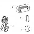
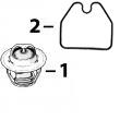
KEY PART NO. PART NAME QTY SERIAL NO. F F F REMARKS
1 .. HOLDER NA X
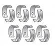
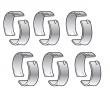
2 T24210 O-RING 6 X
3 R76358 O-RING 1 X
4 14M7297 NUT 3 X M5
5 12H296 WASHER 3 X 0.216"
6 R67879 GASKET 1 X
7 R53899 WASHER 1 X
8 RE36151 CONTROL VALVE 1 X
9 R53901 WASHER 1 X
10 R63016 ADAPTER 1 X
11 R67364 ELBOW FITTING 1 X
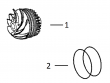
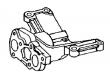
KEY PART NO. PART NAME QTY SERIAL NO. F F F REMARKS
1 RE65265 HAND PRIMER 1 X (SUB FOR RE48048)
2 R54025 WASHER 1 X
3 R26448 O-RING 2 X
4 RE34128 ELBOW FITTING 1 X (IN)
RE10258 ELBOW FITTING 1 X (OUT)
5 R67879 GASKET 1 X
6 RE46375 FUEL PUMP 1 X (ROBERT BOSCH)
7 R93008 WASHER NA X
8 R83489 FITTING NA X
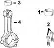
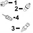
KEY PART NO. PART NAME QTY SERIAL NO. F F F REMARKS
1 RE47431 FUEL LINE 1 X NO. 6
2 RE47430 FUEL LINE 1 X NO. 5
3 RE47429 FUEL LINE 1 X NO. 4
4 R120185 BOLT 5 X
R58186 CLAMP 10 X
R120181 STRAP 5 X
R120182 STRAP 5 X
5 RE47428 FUEL LINE 1 X NO. 3
6 RE47427 FUEL LINE 1 -080424 X
RE502930 FUEL LINE 1 080425- X NO. 2
7 RE47426 FUEL LINE 1 -080424 X
RE502929 FUEL LINE 1 080425- X NO. 1
8 R120186 BOLT 2 X
R71212 CLAMP 1 X
R120183 STRAP 1 X
R120184 STRAP 1 X
R59297 HALF CLAMP 2 X
9 R59305 STRAP 1 X
R58186 CLAMP 1 X
R74030 CLAMP 1 X
R74804 CLAMP 1 X
R120186 BOLT 1 X
R120181 STRAP 1 X
R120182 STRAP 1 X
10 R120185 BOLT 1 X
R59297 HALF CLAMP 2 X
R120183 STRAP 2 X
11 RE55662 ABSORBER 1 X
12 24H1884 WASHER 1 X 13/32" X 13/16" X 0.120" 13/32" X
13/16" X 0.120"
13 19M7166 CAP SCREW 1 X M10 X 20 M10 X 20
14 RE64184 INJECTION NOZZLE 6 X (A) (ROBERT BOSCH)
R51603 O-RING 6 X
15 R84472 WASHER 6 X 7.360 X 18.160 X 2 MM (0.290" X 0.715"
X 0.079") 7.360 X 18.160 X 2 MM
(0.290" X 0.715" X 0.079")
16 R504057 O-RING 6 087550- X
17 RE501970 ADAPTER 6 087550- X
18 R79604 TUBE NUT 6 087550- X
19 R51937 TUBE NUT 1 X
20 AR85519 PLUG 1 X
21 RE500803 FUEL LINE 1 087550- X
22 R77551 O-RING 6 -087549 X
23 R87082 FITTING 6 -087549 X
24 R79604 TUBE NUT 6 -087549 X
25 R79605 WASHER 6 -087549 X
26 R79606 TEE FITTING 6 -087549 X
27 R51936 SEALING WASHER 11 -087549 X
28 RE15807 FUEL LINE 2 -087549 X
29 RE15808 FUEL LINE 2 -087549 X
30 RE36421 FUEL LINE 2 -087549 X
31 R97061 TEE FITTING 1 -087549 X
(A) 2 PINK DOTS
(2) POINT ROSE
(2) ROSAFARBENER PUNKT
(2) PUNTO ROSA
(2) PUNTO ROSADA
(2) ROSAFAERGAD PUNKT
 English
 Espaol
 Franais
 阿拉伯
阿拉伯 中文(简)
中文(简) Deutsch
 Italiano
 Português
 日本
日本 韩国
韩国 български
 hrvatski
 esky
esky Dansk
Dansk Nederlands
 suomi
suomi Ελληνικ
 印度
印度 norsk
norsk Polski
 Roman
Roman русский
 Svenska