 English
 Espaol
 Franais
 阿拉伯
阿拉伯 中文(简)
中文(简) Deutsch
 Italiano
 Português
 日本
日本 韩国
韩国 български
 hrvatski
 esky
esky Dansk
Dansk Nederlands
 suomi
suomi Ελληνικ
 印度
印度 norsk
norsk Polski
 Roman
Roman русский
 Svenska
Perkins2506发动机 柴油发电机维修保养操作调整手册
![]()
英国帕金斯柴油发动机系统的维修保养测试操作手册
Most accidents that involve product operation, maintenance and repair are caused by failure to
observe basic safety rules or precautions. An accident can often be avoided by recognizing potentially
hazardous situations before an accident occurs. A person must be alert to potential hazards. This
person should also have the necessary training, skills and tools to perform these functions properly.
Improper operation, lubrication, maintenance or repair of this product can be dangerous and
could result in injury or death.
Do not operate or perform any lubrication, maintenance or repair on this product, until you have
read and understood the operation, lubrication, maintenance and repair information.
Safety precautions and warnings are provided in this manual and on the product. If these hazard
warnings are not heeded, bodily injury or death could occur to you or to other persons.
The hazards are identified by the “Safety Alert Symbol” and followed by a “Signal Word” such as
“DANGER”, “WARNING” or “CAUTION”. The Safety Alert “WARNING” label is shown below.
The meaning of this safety alert symbol is as follows:
Attention! Become Alert! Your Safety is Involved.
The message that appears under the warning explains the hazard and can be either written or
pictorially presented.
Operations that may cause product damage are identified by “NOTICE” labels on the product and in
this publication.
Perkins cannot anticipate every possible circumstance that might involve a potential hazard. The
warnings in this publication and on the product are, therefore, not all inclusive. If a tool, procedure,
work method or operating technique that is not specifically recommended by Perkins is used,
you must satisfy yourself that it is safe for you and for others. You should also ensure that the
product will not be damag ed or be made unsafe by the operation, lubrication, maintenance or
repair procedures that you choose.
The information, specifications, and illustrations in this publication are on the basis of information that
was available at the time that the publication was written. The specifications, torques, pressures,
measurements, adjustments, illustrations, and other items can change at any time. These changes can
affect the service that is given to the product. Obtain the complete and most current information before
you start any job. Perkins dealers or Perkins distributors have the most current information available.
When
replacement
parts
are
required
for
this
product Perkins recommends using Perkins
replacement parts.
Failure to heed this warning can lead to prema-
ture failures, product damage, personal injury or
death.
![]() KENR6231
KENR6231
3
Table of Contents
Table
of
Contents
Charging System - Test ........................................ 54
Electric Starting System - Test .............................. 55
Index Section
Systems Operation Section
General Information ................................................ 4
Electronic Control System Components ................. 6
Fuel System ........................................................... 8
Air Inlet and Exhaust System ............................... 12
Lubrication System .............................................. 14
Cooling System .................................................... 16
Basic Engine ......................................................... 17
Electrical System ................................................. 18
Testing and Adjusting Section
Testing and Adjusting
Belt Tension Chart ................................................ 22
Fuel System
Fuel System - Inspect ........................................... 23
Air in Fuel - Test .................................................... 23
Electronic Unit Injector - Adjust ............................. 24
Electronic Unit Injector - Test ................................ 24
Finding Top Center Position for No. 1 Piston ........ 25
Fuel Quality - Test ................................................. 26
Fuel System - Prime ............................................. 26
Fuel System Pressure - Test ................................. 27
Gear Group (Front) - Time .................................... 28
Air Inlet and Exhaust System
Air Inlet and Exhaust System - Inspect ................. 31
Turbocharger - Inspect .......................................... 32
Exhaust Temperature - Test .................................. 34
Engine Crankcas e Pressure (Blowby) - Test ........ 35
Engine Valve Lash - Inspect/Adjust ...................... 35
Lubrication System
Engine Oil Pressure - Test .................................... 37
Excessive Bearing Wear - Inspect ........................ 39
Excessive Engine Oil Consumption - Inspect ....... 39
Increased Engine Oil Temperature - Inspect ........ 40
Cooling System
Cooling System - Check (Overheating) ................ 41
Cooling System - Inspect ...................................... 42
Cooling System - Test ........................................... 43
Water Temperature Regulator - Test ..................... 45
Water Pump - Test ................................................ 46
Basic Engine
Piston Ring Groove - Inspect ................................ 47
Connecting Rod Bearings - Inspect ...................... 47
Main Bearings - Inspect ........................................ 47
Cylinder Block - Inspect ........................................ 47
Cylinder Liner Projection - Inspect ........................ 48
Flywheel - Inspect ................................................. 50
Flywheel Housing - Inspect ................................... 51
Vibration Damper - Check .................................... 53
Electrical System
Battery - Test ......................................................... 54
Index ..................................................................... 56

![]() 4
4
Systems Operation Section
KENR6231
Systems
Operat ion
Section
General Information
i02550114
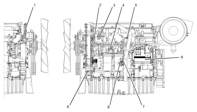
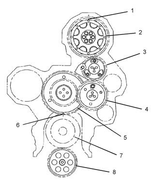
The following model views show the 2506 Engine
features. Due to individual applications, your engine
may appear different from the illustrations.
Illustration 1
Typical example
Left side view
(1) Front timing gear housing
(2) Fuel priming pump
(3) Electronic Control Module (ECM)
(4) Flywheel housing
(5) Fuel filters
(6) Fuel transfer pump
(7) Vibration Damper
g01288248

![]()
![]() KENR6231
KENR6231
Sy stems
5
Operation Section
Illustration 2
Typical example
Right side view
(8) Exhaust manifold
(9) Turbocharger
(10) Temperature regulator housing
(11) Water pump
(12) Oil cooler
(13) Oil filter
g01288247
Starting the Engine
The Electronic Control Module (ECM) will
automatically provide the correct amount of fuel that
is necessary to start the engine. If the engine fails
to start in 30 seconds, the starter s witch should be
released. The starting motor should be allowed to
cool for 30 seconds before being used again.
Cold Mode Operation
The ECM will set the cold start strategy when the
coolant temperature is below 18 °C (64 °F).
Cold mode operation will be deactivated when any of
the following conditions have been met:
• Coolant temperature reaches 18 °C (64 °F).
• The engine has been running for fourteen minutes.
Cold mode operation varies the fuel injection amount
for white smoke cleanup. Cold mode operation also
varies the timing for white smoke cleanup. The
engine operating temperature is usually reached
before the walk-around inspec tion is completed.
![]() 6
6
Systems Operation Section
KENR6231
Electronic
Control
i02589727
System
Components
Illustration 3
(1) Coolant temperature sensor
(2) Camshaft position sensor
(3) Inlet manifold pressure sensor
(4) Fuel temperature sensor
(5) Inlet manifold temperature sensor
(6) Electronic control module (ECM)
(7) Engine oil pressure sensor
(8) Atmospheric pressure sensor
(9) Crankshaft position sensor
g01279775
The electronic control system is integrally designed
into the engine’s fuel system and the engine’s air
inlet and exhaust system in order to electronically
control the fuel delivery and the injection timing. The
•
•
Controls
Outputs
electronic control system provides increased timing
control and fuel air ratio control in comparison to
conventional mechanical engines. Injection timing
is achieved by prec ise control of injector firing time,
and engine rpm is controlled by adjus ting the firing
duration. The Electronic Control Module (ECM)
energizes the solenoid in the unit injector in order to
start the injection of fuel. Also, the ECM de-energizes
the unit injector solenoids in order to stop injection
of fuel. Refer to Systems Operation, Testing and
Adjusting, “Fuel System” for a c omplete explanation
of the fuel injec tion process.
The engine uses the following types of electronic
components:
• Inputs
An input component is one that sends an electrical
signal to the ECM. The signal that is sent varies in
one of the following ways:
• Voltage
• Frequency
• Pulse width
The variation of the signal is in response to a change
in some specific system of the vehicle. The ECM
sees the input sensor signal as information about the
condition, environment, or operation of the vehicle.
![]() KENR6231
KENR6231
Sy stems
7
Operation Section
A c ontrol component (ECM) receives the input
signals. Electronic circuits inside the control
component evaluate the signals from the input
components. These electronic circuits also supply
electrical energy to the output components of the
system. The electrical energy that is supplied to
the output components is based on predetermined
combinations of input signal values.
An output component is one that is operated by a
control module. The output component receives
electrical energy from the control component. The
output component uses that electrical energy in one
of two ways. The output component can use that
electrical energy in order to perform work. The output
component can use that electrical energy in order to
provide information.
![]()
![]() 8
8
Systems Operation Section
KENR6231
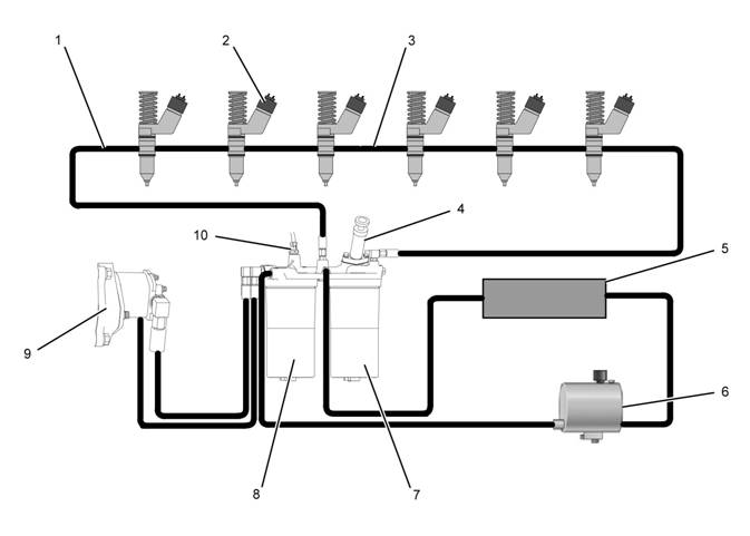
Fuel System
i02550058
Illustration 4
Fuel system schematic
(1) Fuel return line
(2) Electronic unit injectors
(3) Fuel gallery
(4) Fuel priming pump
(5) Fuel cooler
(6) Fuel tank
(7) Secondary fuel filter
(8) Primary fuel filter
(9) Fuel transfer pump
(10) Fuel temperature sensor
g01282152
The fuel supply circuit is a conventional design for
engines with electronic unit injection. A fuel tank (6)
is used to store the fuel prior to use by the engine. A
primary fuel filter/water separator (8) is placed into
the fuel supply circuit in order to remove large debris
from the fuel. This debris may have entered the
fuel tank during fueling. The debris may have also
entered the fuel tank through the vent for the fuel
tank. The primary filter element also separates water
from the fuel. The water is collected in the bowl at the
bottom of the primary fuel filter/water separator.
Note: The inlet fuel temperature to the fuel transfer
pump must not exceed 79 °C (175 °F) when the
engine has reached normal operating temperature.
Fuel temperatures above 79 °C (175 °F) will reduce
the life of the fuel transfer pump chec k valves. The
fuel efficiency and the engine power output are
reduced when the fuel temperature increases from
30 °C (86 °F) to 70 °C (158 °F).
![]()
![]() KENR6231
KENR6231
Sy stems
9
Operation Section
Fuel from the tank (6) flows to the fuel filter base.
The fuel filter base contains the primary fuel filter
and the secondary fuel filter. The fuel flows through
cored passages in the fuel filter base. The fuel
priming pump (4) is mounted on the fuel filter base.
The fuel priming pump is used in order to manually
pump the fuel into the fuel system after the system,
or parts of the system have been drained. The fuel
priming pump is used in order to refill the fuel system
after air has been introduced into the system. For
more information on priming the fuel system, refer
to Systems Operation, Testing and Adjusting, “Fuel
System - Prime”.
As the fuel flows through cored passages in the fuel
filter bas e, the fuel is directed into the primary fuel
filter (8). Fuel flows out of the fuel filter and returns
to the passages in the fuel filter base. Prior to exiting
the fuel filter base, the fuel temperature is sampled
by the fuel temperature sensor (10). The signals
that are generated by the sensors are used by the
engine control in order to monitor the condition of the
engine’s components.
The fuel flows from the fuel filter base to the fuel
transfer pump (9). The fuel transfer pump (9) is a gear
type pump with fixed clearances. The fuel transfer
pump (9) incorporates an internal relief valve that
protects the fuel system from extreme pressure. In
the case of extreme pressure, fuel is redirected back
to the inlet of the fuel transfer pump (9). An outlet
check valve is used in order to prevent pressurized
fuel leakage back through the pump. The fuel transfer
pump (9) is located in the front of the engine. The fuel
transfer pump (9) is driven by the front gear train.
The fuel flows from the fuel transfer pump (9) to the
secondary fuel filter (7). The fuel is filtered in order
to remove small abrasive particles that will cause
premature wear to fuel system components. The fuel
flows from the secondary fuel filter (7) to the fuel filter
base.
The fuel is then directed from the fuel filter base
through the fuel return line (1) to fuel manifold (3) that
runs the length of the cylinder head. A continuous
flow of fuel is supplied to the electronic unit injectors
(2) in order to perform the following tasks:
• Supply fuel for injection
• Remove excessive heat from the injectors.
• Remove air that may accumulate in the fuel
system.
|
filter base. A pressure regulating valve is located in
the fuel filter base. The pressure regulating valve
regulates the pressure for the fuel system. A sufficient
amount of back pressure is maintained in the system
in order to ensure a continuous availability of fuel to
the electronic unit injectors. The fuel flows from the
fuel filter base to the fuel cooler (5). The fuel flows
from the fuel cooler (5) back to the tank (6).
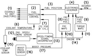
Fuel System Electronic Control
Circuit
Illustration 5
Electronic governor
(1) Signals to the electronic unit injectors
(2) Fuel injection control
(3) Fuel position
(4) Electronic governor
(5) Desired rpm
(6) Coolant temperature
(7) TC for No. 1 cylinder
(8) FRC fuel position
(9) Rated fuel position
(10) FCR maps
(11) Torque maps
(12) Engine s peed/timing sensor
(13) Engine speed/timing signals’ interpreter
(14) Engine rpm
(15) Coolant temperature sensor
(16) Boost pressure sensor
(17) Boost pressure
The injection pump, the fuel lines, and the nozz les
that are used in the traditional Perkins diesel engines
hav e been replaced with an electronically controlled,
mechanically actuated electronic unit injector in each
cylinder. A solenoid on each injector controls the
amount of fuel that is delivered by the injector. An
Electronic Control Module (ECM) sends a signal to
eac h injector solenoid in order to provide complete
control of the engine.

![]() 10
10
Systems Operation Section
KENR6231
Fuel Injection
The ECM controls the amount of fuel that is injected
by varying the signals that are sent to the injectors.
The ECM s ends a high voltage signal to the solenoid
in order to energize the solenoid. The injec tors
will inject fuel only while the injector solenoid is
energized. By controlling the timing and the duration
of the voltage signal, the ECM can control injection
timing and the amount of fuel that is injected.
The ECM sets certain limits on the amount of fuel that
can be injected. “FRC” is a limit which controls the
amount of air and of fuel for the purpose of emission
control. This limit is based on the boost pressure.
When the ECM senses a higher boost pressure, the
ECM increases the “FRC” limit. “Rated Fuel Pos” is
a limit that is based on the horsepower rating of the
engine. This is similar to the rack stops and to the
torque spring on a mechanically governed engine.
“Rated Fuel Pos” provides horsepower and torque
curves for a specific engine family and for a specific
engine rating. All of these limits are programmed into
the personality module by the fac tory. These limits
are not programmable by the service technician.
Injection timing depends on three factors: the engine
speed (rpm), the engine load, and the operational
conditions of the engine. The ECM determines the
top center position of No. 1 cylinder from the signal
that is provided by the engine speed/timing sensor.
The ECM decides when the injection should occur
relative to the top center position. The ECM then
provides the signal to the electronic unit injector at
the desired time.
Electronic Unit Injector Mechanism
Illustration 6 g00291269
Electronic unit injector mechanism
(1) Electronic unit injector
(2) Adjusting nut
(3) Rocker arm assembly
(4) Camshaft lobe
The electronic unit injector mechanism provides
the downward force that is required to pressurize
the fuel in the electronic unit injector pump. The
electronic unit injector (1) allows fuel to be injected
into the combustion chamber with precise timing.
Movement is transmitted from the camshaft lobe (4)
for the electronic unit injector through the rocker arm
assembly (3) to the top of the electronic unit injector.
The adjusting nut (2) allows the injector lash to be
adjusted. For the proper setting of the injector lash,
refer to the topic on adjustment of the electronic unit
injector in Systems Operation, Testing and Adjusting,
“Electronic Unit Injector - Adjust”.
![]()
![]() KENR6231
KENR6231
Sy stems
11
Operation Section
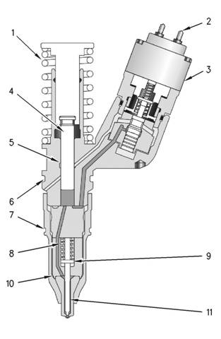
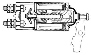
Electronic Unit Injector
Illustration 7
Electronic unit injector
(1) Spring
g00984466
As the electronic unit injector mechanism transfers
the force to the top of the electronic unit injector,
spring (1) is compressed and plunger (4) is driven
downward. This ac tion displaces fuel through the
valve in solenoid valve assembly (3), and into the
return manifold to the fuel tank. As the plunger trav els
downward, the passage in barrel (5) is closed by the
outside diameter of the plunger. The passages within
body (10) and along check valve (11) to the injector
tip already contain fuel for injection. After the passage
in the plunger barrel is closed, the injector is ready for
injection at any time. The start of injection relies on
the software in the Electronic Control Module (ECM).
When the solenoid valve assembly is energized
from a signal across solenoid connection (2), the
valve closes and fuel pressure is elevated in the
injector tip. Injection begins at 34500 ± 1900 kPa
(5000 ± 275 psi) as the force of spring (8) above
spacer (9) is overcome. The check valve begins
to lift from the valve seat. The pressure continues
to rise as the plunger cycles through a full stroke.
After the correct amount of fuel has been disc harged
into the cylinder, the ECM removes the signal to the
solenoid connection. The solenoid valve assembly
is de-energized and the valve in the solenoid valve
assembly is opened. The high pressure fuel is then
dumped through the spill port and into the fuel return
manifold. The fuel is then returned to the fuel tank.
The check valve in the injector tip seats as the
pressure in the tip decreases.
The duration of injection meters the fuel that is
consumed during the fuel injection process. Injection
duration is controlled by the governor logic that is
programmed into the ECM.
As the camshaft lobe rotates past the point of
maximum lobe lift, the force on top of the electronic
(2) Solenoid connection to the Electronic Control Module (ECM)
(3) Solenoid valve assembly
(4) Plunger assembly
(5) Barrel
(6) Seal
(7) Seal
(8) Spring
(9) Spacer
(10) Body
(11) Check valve
Fuel at low pressure from the fuel supply manifold
enters the electronic unit injector at the fill port
through drilled passages in the cylinder head.
unit injector is removed and the spring for the injector
mechanism is allowed to expand. The plunger returns
to the original position. This uncovers the fuel supply
pas sage into the plunger barrel in order to refill the
injector pump body. The fuel at low pressure is again
allowed to circulate through the fuel injector body.
After circulating through the fuel injector body, the
fuel flows out of the spill port. This continues until the
solenoid valve assembly is re-energized for another
injection cycle.
![]()
![]()
![]() 12
12
Systems Operation Section
KENR6231
i02550062
Air Inlet and Exhaust System
Air is forced from the aftercooler into inlet manifold
(1). The air flow from the inlet port into the cylinders
is controlled by inlet valves .
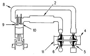
Illustration 8
Air inlet and exhaust system schematic
(1) Inlet to the engine
(2) Aftercooler core
(3) Inlet air line
(4) Exhaust outlet from turbocharger
(5) Turbine side of turbocharger
(6) Compressor side of turbocharger
(7) Air cleaner
g01046036
Illustration 9
Air inlet and exhaust system
(2) Aftercooler core
(4) Exhaust outlet
(5) Turbine side of turbocharger
(6) Compressor side of turbocharger
(8) Exhaust manifold
(9) Exhaust valve
(10) Inlet valve
(11) Air inlet
g00615497
The engine components of the air inlet and exhaust
system control the quality of air and the amount of
air that is available for combustion. The components
of the air inlet and exhaust system are the following
components:
• Air cleaner
• Turbocharger
• Aftercooler
• Cylinder head
• Valves and valve system components
• Piston and cylinder
• Exhaust manifold
The turbocharger compressor wheel pulls inlet air
through the air cleaner and into the air inlet. The air
is compressed and this causes the air to become hot.
The air flows through aftercooler core (2) and the
temperature of the compressed air lowers. This helps
to provide increased horsepower output. Aftercooler
core (2) is a separate cooler core that is mounted in
front of the engine radiator. The engine fan causes
ambient air to move across both cores. This cools the
turbocharged inlet air and the engine coolant.
Each cylinder has two inlet valves (10) and two
exhaust valves (9) in the cylinder head. The inlet
valves open on the inlet stroke. When the inlet valves
open, compressed air from the inlet port within the
inlet manifold is pushed into the cylinder. The inlet
valves c lose when the piston begins the compression
stroke. The air in the cylinder is compressed and the
fuel is injected into the cylinder when the piston is
near the top of the compression stroke. Combustion
begins when the fuel mixes with the air. The force of
combus tion pushes the piston on the power stroke.
The exhaust valves open and the exhaust gases
are pushed through the ex haust port into exhaust
manifold (8). After the piston finishes the exhaust
stroke, the exhaust valves close and the cycle begins
again.
Exhaust gases from the exhaust manifold flow
into the turbine side of turbocharger (5). The high
temperature exhaust gases cause the turbocharger
turbine wheel to turn. The turbine wheel is connected
to the shaft that drives the compressor wheel.
Exhaust gases from the turbocharger pass through
exhaust outlet (4), through a muffler, and through an
exhaust stack.

![]()
![]() KENR6231
KENR6231
Sy stems
13
Operation Section
Turbocharger
Valves And Valve Mechanism
Illustration 10
Turbocharger
(4) Air inlet
(5) Compressor housing
(6) Compressor wheel
(7) Bearing
(8) Oil inlet port
(9) Bearing
(10) Turbine housing
(11) Turbine wheel
(12) Exhaust outlet
g00291085
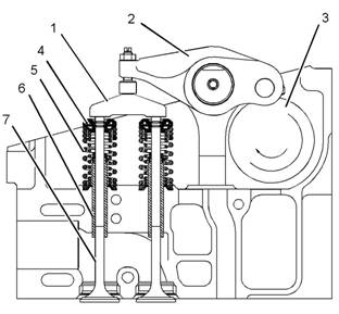
Illustration 11
Valve system components
(1) Valve bridge
(2) Rocker arm
(3) Camshaft
(4) Rotocoil
(5) Valve spring
(6) Valve guide
(7) Valve
g01046041
(13) Oil outlet port
(14) Exhaust inlet
Turbocharger (3) is mounted to exhaust manifold (2)
of the engine. All of the exhaust gases go from the
exhaust manifold through the turbocharger.
The exhaust gases enter the turbocharger and the
turbine wheel is turned. Because the turbocharger
turbine wheel is connected by a shaft to the
turbocharger compres sor wheel, the turbine wheel
and the compressor wheel turn at very high speeds.
The rotation of the compressor wheel pulls clean
air through the compressor housing air inlet. The
action of the compressor wheel blades causes a
compression of the inlet air. This compression allows
a larger amount of air to enter the engine. With more
air in the engine, the engine is able to burn more fuel.
The overall effect is an increase in power.
Bearing (7) and bearing (9) in the turbocharger use
engine oil that is under pressure for lubrication. The
lubrication for the bearings flows through oil inlet port
(8) and into the inlet port in the center section of the
turbocharger cartridge. The oil exits the turbocharger
through oil outlet port (13). The oil then returns to
the engine oil pan through the oil drain line for the
turbocharger.
The valves and the valve mechanism control the flow
of inlet air into the c ylinders during engine operation.
The valves and the valve mechanism control the flow
of exhaust gases out of the cylinders during engine
operation.
![]()
![]()
![]() 14
14
Systems Operation Section
KENR6231
Rotocoils (4) cause the valves to rotate while the
engine is running. Valve rotation provides a longer
service life. Valve rotation also minimizes carbon
deposits on the valves.
Adjustable idler gear (10) is designed to provide the
required gear backlash between nonadjustable idler
gear (11) and camshaft gear (9). If the cylinder head is
removed, tolerances of the components will change.
The components that change are the cylinder head
and the head gasket. The adjustable idler gear must
be relocated. For information on setting the correct
bac klash, refer to Systems Operation, Tes ting and
Adjusting, “Gear Group (Front) - Time”.
The camshaft drive gear has integral pendulums
which act as a vibration damper for the front gear
group. These pendulums are designed to counteract
the torsional forces from the injector pulses. This
eliminates vibration and noise. The engine also runs
smoother at all operating speeds.
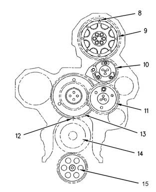
Lubrication System
i02550074
Illustration 12
Components of the gear train
(8) Timing mark
(9) Camshaft gear
(10) Adjustable idler gear
(11) Idler gear
(12) Timing mark
(13) Cluster gear
(14) Crankshaft gear
(15) Oil pump gear
g01033757
Lubrication System Components
The lubrication system has the following components:
• Oil pan
• Oil pump
• Oil cooler
The inlet valves and the exhaust valves are opened
by the valve mechanism. The inlet valves and
the exhaust valves are also closed by the valve
mechanism. This occurs as the rotation of the
crankshaft causes camshaft (3) to rotate. Camshaft
gear (9) is driven by a series of two idler gears (10)
and (11). Idler gear (11) is driven by cluster gear (13).
Cluster gear (13) is driven by crankshaft gear (14).
Timing mark (12) and timing mark (8) are aligned in
order to provide the correct relationship between the
piston and the valve movement.
The camshaft has three lobes for each cylinder.
One lobe operates the inlet valves. A second lobe
operates the exhaust valves. The third lobe operates
the unit injector mechanism. The camshaft lobes turn
and the rocker arms move. Movement of the rocker
arms will make the inlet and ex haust valve bridges
move. These bridges allow one rocker arm to actuate
two valves at the same time. Each cylinder has two
inlet valves and two exhaust valves. Each valve has
one valve spring (5). The spring closes the valve.
•
•
•
Oil filter
Turbocharger oil lines
Oil passages for the cylinder block


![]()
![]()
![]() KENR6231
KENR6231
Sy stems
15
Operation Section
Oil Flow Through The Oil Filter And Oil
Cooler
Illustration 13
Oil flow when the engine is warm.
(1) Oil manifold
(2) Oil supply line
(3) Oil return line
(4) Oil filter
(5) Bypass valve for the oil filter
(6) Oil pan
(7) Oil pump
(8) Bypass valve for the oil cooler
(9) Suction lines
(10) Oil cooler
g00562123
Illustration 14
Oil flow when the engine Is cold.
(1) Oil manifold
(2) Oil supply line
(3) Oil return line
(4) Oil filter
(5) Bypass valve for the oil filter
(6) Oil pan
(7) Oil pump
(8) Bypass valve for the oil cooler
(9) Suction lines
(10) Oil cooler
(11) Bypass valve for the oil pump
g00562383
(11) Bypass valve for the oil pump
When the engine is warm, oil is drawn from the oil
pan (6) through the suc tion lines (9) to the oil pump
(7). The oil pump pushes the hot oil through the oil
cooler (10). The oil is then sent to the oil filter (4).
Oil from the oil filter is sent to the oil manifold (1) in
the cylinder block and to the oil supply line (2) for the
turbocharger. Oil from the turbocharger goes back
through the oil return line (3) to the oil pan.
When the engine is cold, oil is drawn from the oil
pan (6) through the suction lines (9) to the oil pump
(7). When the oil is cold, an oil pressure differential
in the bypass valves causes the bypass valves to
open. These bypass valves then provide immediate
lubrication to all of the engine components when cold
oil with high viscosity causes a restriction to oil flow
through the oil cooler (10) and the oil filter (4). The oil
pump then pushes the cold oil through the bypass
valve (8) for the oil cooler and through the bypass
valve (5) for the oil filter. The oil then goes to the oil
manifold (1) in the cylinder block and to the supply
line (2) for the turbocharger. Oil from the turbocharger
goes back through the oil return line (3) to the oil pan.
When the oil is warm, an oil press ure differential in
the bypass valves also causes the bypass valves to
close. There is normal oil flow through the oil cooler
and the oil filter.
The by pass valves will also open when there is
a restriction in the oil cooler or the oil filter. This
prevents a restricted oil filter or a res tricted oil cooler
from stopping the lubrication of the engine. The
system pressure is limited by the oil pump bypass
valve (11).

![]()
![]()
![]() 16
16
Systems Operation Section
KENR6231
Oil Flow In The Engine
Illustration 15
Engine oil flow sc hematic
(1) Rocker arm shaft
(2) Oil passage to air compressor
(3) Camshaft bearing journals
(4) Oil passage to adjustable idler gear
(5) Oil passage to the fixed idler stub shaft
(6) Oil passage to cluster idler gear
(7) Oil manifold
(8) Pis ton cooling jet
(9) Crankshaft main bearings
(10) Oil passage from filter
g00431790
The oil from the oil manifold (7) is sent under
pressure through drilled passages to the crankshaft
main bearings (9). The oil flows through drilled holes
in the crankshaft. This oil lubricates the connecting
rod bearings. A small amount of oil is sent to the
piston cooling jets (8). The piston cooling jets spray
oil on the underside of the pistons.
Oil flows through passages in the timing gear housing
and the accessory drive gear. This oil flows to the air
compressor through the oil passage (2).
Oil passage (4) prov ides oil to the adjustable idler
gear. Oil passage (5) provides oil to the fixed idler
gear. Oil passage (6) provides oil to the cluster gear.
The oil flows through a passage in the shafts of the
gears.
There is a pressure control valve in the oil pump.
This valve controls the pressure of the oil that flows
from the oil pump.
Oil passage (9) provides lubrication to the rear
crankshaft seal. This ensures a long service life for
the rear crankshaft seal.
Oil flows into the cylinder head via a hollow locating
dowel in the top deck of the cylinder block. Oil trav els
to the camshaft bearing journals (3) and the three
center rocker arm shaft supports through drilled
passages in the cylinder head. The supports supply
oil to each rocker shaft. Oil flows to the bushings of
the fuel injec tor rocker arm through holes in the rocker
arm s haft (1). This same oil lubricates the valve and
the rollers. Oil flows through drilled passages in the
rocker arms. This oil lubricates the roller, the valve
bridge and the contact surfaces of the actuator of the
unit injector. Splash oil lubrication is used to lubricate
other components of the valve system.
Excess oil returns to the engine oil pan.
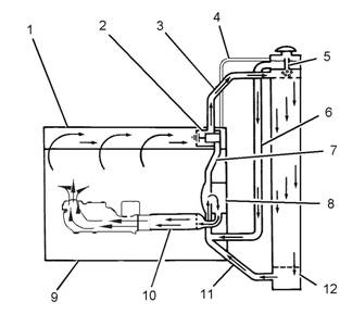
i02550118
Cooling System
This engine has a pressure type cooling system that
is equipped with a shunt line.
![]() KENR6231
KENR6231
Sy stems
17
Operation Section
|
advantages. First, the cooling system can be
operated safely at a temperature that is higher than
the boiling point of water. Next, cavitation in the water
pump is prevented. It is more difficult for air or steam
pockets to be made in the cooling system.
Note: Use Perkins ELC in an Air-To-Air Aftercooler
system. Refer to Operation and Maintenance Manual,
“Fluid Recommendations” for more information. This
keeps the temperature range of the coolant high
enough for efficient performance.
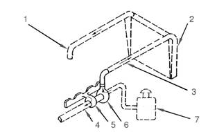
Illustration 16
Cooling system for a warm engine
(1) Cylinder head
(2) Water temperature regulator
(3) Outlet pipe
(4) Vent line
(5) Vent tube
(6) Shunt line
(7) Pipe
(8) Water pump
(9) Cylinder block
(10) Oil cooler
(11) Inlet pipe
(12) Radiator
In operation, the water pump (8) sends most of the
coolant from the radiator (12) to the oil cooler (10).
The coolant from the oil cooler (10) goes into the
cylinder block (9) through a bonnet and an elbow.
The coolant goes around the cylinder liners, through
the water directors and into the cylinder head.
The water directors send the flow of coolant around
the valves and the passages for exhaust gases in the
cylinder head. The coolant then goes to the front of
the cylinder head. At this point, water temperature
regulator (2) controls the direction of coolant flow.
The water temperature regulator (2) is c losed when
the engine is cold. The coolant flows through the
regulator housing and pipe (7) back to water pump
(8).
If the coolant is at normal operating temperature,
the water temperature regulator (2) opens and the
coolant flows to the radiator (12) through the outlet
pipe (3). The coolant becomes cooler as the coolant
moves through the radiator. When the coolant gets to
the bottom of the radiator, the coolant goes through
the inlet pipe (11) and into the water pump (8).
Note: The water temperature regulator (2) is an
important part of the cooling system. The water
temperature regulator (2) divides the coolant flow
between the radiator (12) and the bypass pipe (7).
This will maintain the correct temperature. If the
water temperature regulator is not installed in the
system, there is no mechanical control. Most of the
coolant will go through the bypass. This will cause
the engine to overheat in hot weather. If a higher
volume of c oolant goes through the radiator, the
engine will not reach normal operating temperatures.
This occurs during cold weather.
Shunt line (6) gives several advantages to the c ooling
system. The shunt line gives a positiv e coolant
pressure at the water pump inlet that prev ents pump
cavitation. A small flow of coolant constantly goes
through shunt line (6) to the inlet of water pump
(8). This causes a small amount of coolant to move
constantly through the vent tube (5). The flow through
the vent tube is small and the volume of the upper
compartment is large. Air in the coolant is removed
as the coolant goes into the upper compartment.
The vent line is used to fill the cooling system with
coolant for the first time. This will purge any air out of
the top of a bottom filled system.
i02550119
Basic Engine
Cylinder Block Assembly
Passages supply the lubrication for the crankshaft
bearings and the piston crowns. These passages
are cast into the cylinder block. Oil is supplied to the
pas sages by the cylinder block’s oil manifold.
The cylinder liner is an induction hardened liner. A
steel spacer plate provides improved reusability and
durability.
![]() 18
18
Systems Operation Section
KENR6231
Cylinder Head Assembly
The cylinder head is a one-piece cast iron head. The
cylinder head supports the camshaft. Steel reinforced
bearings are pressed into each bore. The bearings
are lubricated under pressure. Bridge dowels have
been eliminated as the valve train uses floating valve
bridges.
Thermal efficiency is enhanced by the use of
stainless steel thermal sleeves in each exhaust port.
The sleeves reduce the amount of heat rejection to
the cooling system. The sleeves then transfer the
thermal energy to the turbocharger.
The unit injector is mounted in a stainless steel
adapter. This adapter has been pressed into the
cylinder head injector bore.
Pistons, Rings And Connecting
Rods
The piston is a one-piece steel design that is retained
by the piston pin to the small end of the connecting
rod. The pistons have three rings that are located
in grooves in the steel crown. These rings seal the
combustion gas . The rings provide control of the oil.
The top ring has a barrel face. The second ring has
a tapered face and the ring has a coating of chrome
finish for the face. The third ring is the oil ring. The
third ring has a coil spring expander.
The connecting rod is a conventional design. The
cap of the connecting rod is attached to the shank by
two bolts that are threaded into the shank. Each side
of the small end of the connecting rod is machined
at an angle of 12 degrees in order to fit within the
piston cavity.
Crankshaft
The crankshaft converts the combustion force in the
cylinder into rotating torque. A v ibration damper is
used at the front of the crankshaft in order to reduce
the torsional vibrations.
The crankshaft drives a group of gears (front gear
train) on the front of the engine. The front gear
train provides power for the following components:
camshaft, water pump, oil pump, fuel transfer
pump, and accessory items that are specific to the
applic ation.
The cylinder block has seven main bearings that
support the crankshaft. The cylinder block uses two
bolts to hold each of the bearing caps to the block.
The crankcase uses a lip seal at both ends of the
crankshaft.
Camshaft
The camshaft has three lobes at each cylinder.
These lobes allow the camshaft to operate the unit
injector, the exhaust valves, and the inlet valves. The
camshaft is supported in the cylinder head by s even
journals which are fit with bearings. The camshaft
gear contains integral roller dampers that counteract
the torsional vibrations that are generated by the
high fuel pressure during fuel injector operation. The
des ign reduces gear train noise. The camshaft is
driven by an adjustable idler gear which is turned by
a fixed idler gear which is turned by a cluster idler
gear in the front gear train. Each bearing journal is
lubricated from the oil manifold in the cylinder head.
A thrust plate that is located at the front controls the
end play of the camshaft. Timing of the camshaft is
accomplished by aligning marks on the crankshaft
gear and idler gear, and camshaft gear with a mark
on the front timing plate.
i02554889
Electrical System
Grounding Practices
Proper grounding for the machine electrical sy stem
and engine electrical systems is necessary for
proper machine performance and reliability. Improper
grounding will res ult in uncontrolled electrical circuit
paths and unreliable electrical circuit paths.
Uncontrolled engine electrical circuit paths can result
in damage to main bearings, crankshaft bearing
journal surfaces, and aluminum components.
To ensure proper functioning of the vehicle and
engine electrical systems, an engine-to-frame ground
strap with a direct path to the negative battery post
must be used. This may be provided by way of a
starting motor ground, a frame to starting motor
ground, or a direct frame to engine ground.
An engine-to-frame ground strap must be used in
order to connect the grounding stud of the engine to
the frame of the vehicle and to the negative battery
post.

![]()
![]()
![]()
![]()
![]() KENR6231
KENR6231
Sy stems
19
Operation Section
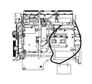
Illustration 17
Typical example
Grounding Stud To Battery Ground (“-”)
Illustration 18
Typical example
Alternate Grounding Stud To Battery Ground (“-”)
g01028488
g01028479
NOTICE
When boost starting an engine, the instructions in Op-
eration and Maintenance Manual, “Engine Starting”
should be followed in order to properly start the en-
gine.
This engine is equipped with a 24 volt starting system.
Only equal voltage for boost starting should be used.
The use of a higher voltage will damage the electrical
system.
The Electronic Control Module (ECM) must be dis-
connected at the “J1/P1” and “J2/P2” locations before
welding on the vehicle.
The engine has several input components which are
electronic. These components require an operating
voltage.
Unlike many electronic systems of the past, this
engine is tolerant to common external sources of
electrical noise. Buzzers that use electrical energy
can cause disruptions in the power supply. If buzz ers
are used anywhere on the machine, the engine
electronics should be powered directly from the
battery system through a dedicated relay. The engine
electronics should not be powered through a common
power bus with other keyswitch activated devices.
Engine Electrical System
The electrical system has the following separate
circuits :
• Charging
• Starting (If equipped)
• Accessories with low amperage
The charging circuit is in operation when the engine
is running. An alternator makes electricity for the
The engine must have a wire ground to the battery.
Ground wires or ground straps should be combined
at ground studs that are only for ground use. All of
the grounds should be tight and free of corros ion.
All of the ground paths must be capable of carrying
any likely current faults. An AWG #0 or larger wire is
recommended for the grounding strap to the cylinder
head.
The engine alternator should be battery ground
with a wire size that is capable of managing the full
charging current of the alternator.
charging circuit. A voltage regulator in the circuit
controls the electrical output in order to keep the
battery at full charge.
The starting circuit is activated only when the start
switch is activated.
Charging System Components
Alternator
The alternator is driven by a belt from the cranks haft
pulley. This alternator is a three-phase, self-rectifying
charging unit, and the regulator is part of the
alternator.
![]()
![]()
![]()
![]() 20
20
Systems Operation Section
KENR6231
The alternator design has no need for s lip rings
and the only part that has movement is the rotor
assembly. All conductors that carry current are
stationary. The following conductors are in the circuit:
• Field winding
• Stator windings
• Regulator circuit components
The rotor assembly has many magnetic poles that
look like fingers with air space between each of the
opposite poles. The poles have residual magnetism.
The residual magnetism produces a small magnetic
field between the poles. As the rotor as sembly
begins to turn between the field winding and the
stator windings, a small amount of alternating current
(AC) is produced. The AC current is produced in the
stator windings from the small magnetic field. The
AC current is changed to direct current (DC) when
the AC current passes through the diodes of the
rectifier bridge. The current is used for the following
applications:
• Charging the battery
• Supplying the accessory circuit that has the low
amperage
• Strengthening the magnetic field
The first two applications use the majority of the
current. As the DC current increases through the
field windings, the s trength of the magnetic field is
increased. As the magnetic field becomes stronger,
more AC current is produced in the stator windings.
The increased speed of the rotor assembly also
increases the current and voltage output of the
alternator.
The voltage regulator is a solid-state electronic
switch. The voltage regulator senses the voltage in
the system. The voltage regulator switches ON and
OFF many times per second in order to control the
field current for the alternator. The alternator uses
the field current in order to generate the required
voltage output.
NOTICE
Never operate the alternator without the battery in the
circuit. Making or breaking an alternator connection
with heavy load on the circuit can cause damage to
the regulator.
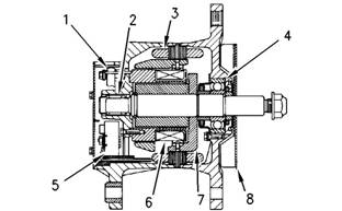
Illustration 19
Typical alternator components
(1) Regulator
(2) Roller bearing
(3) Stator winding
(4) Ball bearing
(5) Rectifier bridge
(6) Field winding
(7) Rotor assembly
(8) Fan
Starting System Components
Starting Solenoid
Illustration 20
Typical starting solenoid
g00425518
g00317613
![]()
![]() KENR6231
KENR6231
Sy stems
21
Operation Section
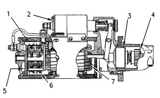
Illustration 21
Typical starting motor components
(1) Field
(2) Solenoid
(3) Clutch
(4) Pinion
(5) Commutator
(6) Brush assembly
(7) Armature
g00425521
When two sets of solenoid windings are used, the
windings are called the hold-in winding and the
pull-in winding. Both sets of windings have the same
number of turns around the cylinder, but the pull-in
winding uses a wire with a larger diameter. The wire
with a larger diameter produces a greater magnetic
field (1). When the start switch is closed, part of the
current flows from the battery through the hold-in
windings. The rest of the current flows through the
pull-in windings to the motor terminal. The current
then flows through the motor to ground. Solenoid
(2)is fully activated when the connection across the
battery and the motor terminal is complete. When
solenoid (2) is fully activated, the current is shut
off through the pull-in windings. At this point, only
the smaller hold-in windings are in operation. The
hold-in windings operate for the duration of time that
is required in order to start the engine. Solenoid (2)
will now draw less current from the battery, and the
heat that is generated by solenoid (2) will be kept at
an acceptable level.
The starting solenoid (2) is an electromagnetic s witch
that performs the following basic operations:
• The starting solenoid (2) closes the high current
starting motor circuit with a low current start switch
circuit.
• The starting solenoid (2) engages the pinion of the
starting motor (4) with the ring gear.
Solenoid (2) has windings (one or two sets) around
a hollow cylinder. A plunger that is spring loaded is
inside the cylinder. The plunger can move forward
and backward. When the start switch is closed and
electricity is sent through the windings, a magnetic
field (1) is made. The magnetic field (1) pulls the
plunger forward in the cylinder. This moves the shift
lever in order to engage the pinion drive gear with the
ring gear. The front end of the plunger then makes
contact across the battery and motor terminals of
solenoid (2). Next, the starting motor begins to turn
the flywheel of the engine.
When the start switch is opened, current no longer
flows through the windings. The spring now pushes
the plunger back to the original position. At the same
time, the spring moves the pinion gear away from
the flywheel.
| |||||||||||||||||||||
| |||||||||||||||||||||
Testing and Adjusting Section
KENR6231
Testing
Section
and
Adjusting
Testing
and
Adjusting
Belt
Tension Chart
i02555248
Table 1
|
Required Tools | |||
|
Tool |
Part Number |
Part Description |
Qty |
|
A |
- |
Belt Tension Gauge |
1 |
Table 2
Size of Belt
Width of Belt
(1)
(2)
Initial Belt Tension refers to a new belt.
Used Belt Tension refers to a belt that has been in operation for 30 minutes or more at the rated speed.
Install Tooling (A) at the center of the longest free
length of belt and check the tension on the belt.
Check and adjust the tension on the tightest belt.
To adjust the belt tension, refer to Disassembly and
Assembly, “Belt Tightener - Install”.
Note: When the belts are replaced, always replace
the belts as a set.
Table 3
Size of Belt
Width of Belt
(1)
(2)
Initial Belt Tension refers to a new belt.
Used Belt Tension refers to a belt that has been in operation for 30 minutes or more at the rated speed.
Install Tooling (A) at the center of the longest free
length of belt and check the tension on the belt.
Check and adjust the tension on the tightest belt.
To adjust the belt tension, refer to Disassembly and
Assembly, “Alternator - Install”.
![]() KENR6231
KENR6231
23
Testing and Adjusting Section
Fuel
System
i02550123
•
•
Relief valves
Check valves
Fuel System - Inspect
A problem with the components that send fuel to
the engine can cause low fuel pressure. This can
decrease engine performance.
1. Check the fuel level in the fuel tank. Ensure that
the v ent in the fuel cap is not filled with dirt.
2. Check all fuel lines for fuel leakage. The fuel lines
must be free from restrictions and faulty bends.
Verify that the fuel return line is not collapsed.
3. Install a new fuel filter.
4. Cut the old filter open with a suitable filter cutter.
Inspect the filter for excess contamination.
Determine the source of the contamination. Make
the necessary repairs.
5. Service the primary fuel filter (if equipped).
6. Operate the hand priming pump (if equipped).
If excessive resistance is felt, inspect the fuel
pressure regulating valv e. If uneven resistance
is felt, test for air in the fuel. Refer to Systems
Operation, Testing and Adjusting, “Air in Fuel -
Test” for more information.
7. Remove any air that may be in the fuel system.
Refer to Sy stems Operation, Testing and
Adjusting, “Fuel System - Prime”.
i02550146
Air in Fuel - Test
This procedure checks for air in the fuel. This
procedure also assists in finding the source of the air.
1. Examine the fuel system for leaks. Ensure that
the fuel line fittings are properly tightened. Check
the fuel level in the fuel tank. Air can enter the
fuel system on the suction side between the fuel
transfer pump and the fuel tank.
2. Install a suitable fuel flow tube with a visual sight
gauge in the fuel return line. When possible, install
the sight gauge in a straight section of the fuel line
that is at least 304.8 mm (12 inches) long. Do not
ins tall the sight gauge near the following devices
that c reate turbulence:
• Elbows
|
Look for air bubbles in the fuel. If there is no fuel
in the sight gauge, prime the fuel system. Refer to
System Operation, Testing and Adjusting, “Fuel
System - Prime” for more information. If the engine
starts, check for air in the fuel at varying engine
speeds. When possible, operate the engine under
the conditions which have been suspect of air in
the fuel.
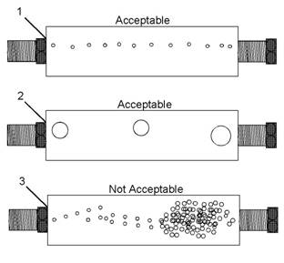
Illustration 22
(1) A steady stream of s mall bubbles with a diameter of
approximately 1.60 mm (0.063 inch) is an acceptable amount
of air in the fuel.
(2) Bubbles with a diameter of approximately 6.35 mm (0.250 inch)
are also acceptable if there is two sec onds to three seconds
intervals between bubbles.
(3) Excessive air bubbles in the fuel are not acceptable.
3. If excessive air is seen in the sight gauge in the
fuel return line, install a second s ight gauge at the
inlet to the fuel transfer pump. If a second sight
gauge is not available, move the sight gauge from
the fuel return line and install the sight gauge
at the inlet to the fuel transfer pump. Observe
the fuel flow during engine crank ing. Look for air
bubbles in the fuel. If the engine starts, check for
air in the fuel at varying engine speeds.
If excessive air is not seen at the inlet to the fuel
transfer pump, the air is entering the system after
the fuel transfer pump. Proc eed to Step 6.
If excessive air is seen at the inlet to the fuel
transfer pump, air is entering through the suction
side of the fuel system.
![]()
![]()
![]() 24
24
Testing and Adjusting Section
KENR6231
To avoid personal injury, always wear eye and face
protection when using pressurized air.
4. Pressurize the fuel tank to the recommendations
of the OEM in order to avoid damage to the fuel
tank. Check for leaks in the fuel lines between
the fuel tank and the fuel transfer pump. Repair
any leaks that are found. Check the fuel pressure
in order to ensure that the fuel transfer pump is
operating properly. For information about checking
the fuel pressure, see System Operation, Testing
and Adjusting, “Fuel System Pressure - Test”.
5. If the source of the air is not found, disconnec t
the s upply line from the fuel tank and connect an
external fuel supply to the inlet of the fuel transfer
pump. If this corrects the problem, repair the fuel
tank or the stand pipe in the fuel tank.
6. If the injector sleev e is worn or damaged,
combustion gases may be leaking into the fuel
system. Also, if the O-rings on the injector sleeves
are worn, missing, or damaged, combustion gases
may leak into the fuel system.
i02550152
Electronic Unit Injector - Adjust
Table 4
Required Tools
Tool Part Number Part Description Qty
A CH11149 Injector Height Gauge 1
To make an adjustment to the unit injectors on
cylinders 3, 5, and 6 us e the following procedure:
1. Put the No. 1 piston at the top center position
on the compression stroke. Refer to Systems
Operation, Testing and Adjusting, “Finding Top
Center Position for No. 1 Piston”.
2. Use Tooling (A) in order to obtain a dimension of
78.0 ± 0.2 mm (3.07 ± 0.01 inch). The dimension
is measured from the top of the unit injector to the
machined ledge of the fuel injector body.
3. Turn the adjusting screw for the unit injector (2)
cloc kwise until the correct height is obtained.
4. Hold the adjusting screw in this position and
tighten locknut (3) to a torque of 100 ± 10 N·m
(74 ± 7 lb ft).
5. To make an adjustment to the unit injectors on
cylinders 1, 2, and 4, remove the timing bolt. Turn
the flywheel by 360 degrees in the direction of
engine rotation. The direction of engine rotation is
counterclockwise, as the engine is viewed from
the flywheel end. This will put the number 1 piston
at the top center position on the exhaust stroke.
6. Repeat Steps 3 through 4.
7. Remove the timing bolt from the flywheel after all
the unit injector adjustments have been made.
Reinstall the valve mechanism cover.
i02550163
Electronic Unit Injector - Test
This procedure assists in identifying the cause for
an injector misfiring. Perform this procedure only
after performing the Cylinder Cutout Test. Refer to
Troubleshooting for more information.
1. Check for air in the fuel, if this procedure has
not already been performed. Refer to Systems
Operation, Testing and Adjusting, “Air in Fuel -
Test”.
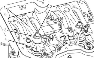
Illustration 23
Injector Mechanism (Typical example)
(1) Rocker arm
(2) Adjusting screw
(3) Locknut
(4) CH11149 Injector Height Gauge
g01023138
Electrical shock hazard. The electronic unit injec-
tor system uses 90-120 volts.
| |||||||||||||||||
25
Testing and Adjusting Section
2.
Remove the valve cover and look for broken
parts. Repair any broken parts or replace any
broken parts that are found. Inspect all wiring to
the solenoids. Look for loos e connections. Also
Finding
Top
Center
i02551444
Position
look for frayed wires or broken wires. Ens ure
that the connector for the unit injector solenoid
is properly connected. Perform a pull test on
each of the wires. Refer to Troubleshooting,
“Elec trical Connectors - Inspect”. Inspect the pos ts
of the solenoid for arcing. If arcing or evidence
of arcing is found, remove the cap assembly.
Refer to Disassembly and Assembly, “Elec tronic
Unit Injector - Remove”. Clean the connecting
posts. Reinstall the cap assembly and tighten
the solenoid nuts to a torque of 2.5 ± 0.25 N·m
(22 ± 2 lb in). Refer to Disassembly and Assembly ,
for No. 1
Table 5
Piston
3.
4.
5.
6.
“Electronic Unit Injector - Install”.
Check the valve lash setting for the cylinder of the
suspect unit injector. Refer to Systems Operation,
Testing and Adjusting, “Engine Valve Lash -
Inspect/Adjust”.
Ensure that the bolt that holds the unit injector is
tightened to the proper torque. If necessary, loosen
the bolt that holds the unit injector and tighten the
bolt to a torque of 55 ± 10 N·m (40.6 ± 7.4 lb ft).
Remove the suspect unit injector and check the
unit injector for signs of exposure to coolant. Refer
to Disassembly and Assembly, “Electronic Unit
Injector - Remove”. Exposure to coolant will cause
rust to form on the injec tor. If the unit injector
shows signs of exposure to coolant, remove the
injector sleev e and inspect the injector sleeve.
Refer to Disassembly and Assembly, “Elec tronic
Unit Injector Sleeve - Remove”. Replace the
injector sleeve if the injector sleeve is damaged.
Check the unit injector for an exc essive brown
dis coloration that extends beyond the injector tip. If
excessive discoloration is found, check the quality
of the fuel. Refer to Systems Operation, Testing
and Adjusting, “Fuel Quality - Test”. Replace the
seals on the injector and reinstall the injector.
Refer to Disassembly and Assembly, “Elec tronic
Unit Injector - Install”. Also refer to Disassembly
and Assembly, “Electronic Unit Injector Sleeve -
Install”.
If the problem is not resolved, replace the suspect
injector with a new injector.
|
compression stroke is the starting point of all timing
procedures.
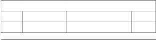
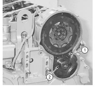
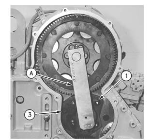
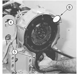
Illustration 24
Typical example
1. Remove both bolts (3) and cover (2) from the
flywheel housing. Remove the plug (1) from the
timing hole in the flywheel hous ing.
2. Install Tooling (A) into the flywheel housing
through the aperture behind the cover (2). Tooling
(A) is used in order to turn the engine flywheel in
the direction of normal engine rotation. Normal
engine rotation is counterclockwise. Normal
engine rotation is viewed from the flywheel end of
the engine. Turn the engine flywheel until Tooling
(B) engages with the threaded hole in the flywheel.
![]()
![]()
![]() 26
26
Testing and Adjusting Section
KENR6231
Note: If the flywheel is turned beyond the point
of engagement, the flywheel must be turned in
the opposite direction of normal engine rotation
approximately 45 degrees. Then turn the flywheel in
the direction of normal rotation until the timing bolt
engages with the threaded hole. The procedure will
eliminate the backlash that will occur when the No. 1
piston is put on the top center.
3. Remove the front valve mechanism cover from
the engine.
4. The inlet and exhaust valves for the No. 1 cylinder
are fully closed if the No. 1 piston is on the
compression stroke and the rocker arms can be
moved by hand. If the roc ker arms can not be
moved and the valves are slightly open the No. 1
pis ton is on the exhaust stroke.
Note: After the actual stroke position is identified,
and the other s troke position is needed, remove the
timing bolt from the flywheel. The flywheel is turned
360 degrees in a counterclockwise direction. The
3.
Refer to Operation and Maintenance Manual,
“Fuel Recommendations” for more information.
If fuel quality is still suspected as a possible
cause to problems regarding engine performance,
dis connect the fuel inlet line, and temporarily
operate the engine from a separate source of
fuel that is known to be good. This will determine
if the problem is caused by fuel quality. If fuel
quality is determined to be the problem, drain the
fuel system and replace the fuel filters. Engine
performance can be affected by the following
characteristics:
• Cetane number of the fuel
• Air in the fuel
• Other fuel characteristics
i02551471
timing bolt is reinstalled.
Fuel System - Prime
Fuel Quality - Test
i02551477
NOTICE
Use a suitable container to c atch any fuel that might
spill. Clean up any spilled fuel immediately.
Ensure that all adjustments and repairs are performed
by authorized personnel that have had the correct
training.
Use the following procedure to test for problems
regarding fuel quality:
1. Determine if water and/or contaminants are
present in the fuel. Check the water separator (if
equipped). If a water separator is not present,
proceed to Step 2. Drain the water separator, if
neces sary. A full fuel tank minimizes the potential
for overnight condensation.
Note: A water separator can appear to be full of fuel
when the water separator is actually full of water.
2. Determine if contaminants are present in the
fuel. Remove a sample of fuel from the bottom
of the fuel tank. Visually inspect the fuel sample
for contaminants. The color of the fuel is not
necessarily an indication of fuel quality. However,
fuel that is black, brown, and/or similar to sludge
can be an indication of the growth of bacteria or
oil contamination. In cold temperatures, cloudy
fuel indicates that the fuel may not be suitable for
operating conditions.
NOTICE
Do not allow dirt to enter the fuel system. Thoroughly
clean the area around a fuel system component that
will be disconnected. Fit a suitable cover over discon-
nec ted fuel system component.
Note: This procedure is most common when the
engine has run out of fuel.
1. Turn the ignition switch to the “OFF” position.
2. Fill the fuel tank(s) with clean diesel fuel.
![]()
![]()
![]()
![]() KENR6231
KENR6231
27
Testing and Adjusting Section
•
The engine starts, but the engine continues to
misfire or smoke.
9.
Run the engine with no load until the engine runs
smoothly.
i02571703
Fuel System Pressure - Test
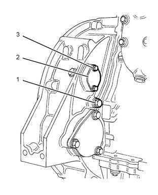
Illustration 25
Typical example
g01282239
|
|
Low fuel pressure can cause low power. Low fuel
pressure can also cause cavitation of the fuel
which can damage the fuel injectors. The following
conditions can cause low fuel pressure:
• Plugged fuel filters
pump
• Debris in the pressure regulating valve
• Partially open check valve
the fuel transfer pump
3.
Loosen the union of the pipe for the fuel(1).
•
Severe wear on return fuel pressure regulating
valve in the fuel filter base
Note: Do not remove the union completely. Open the
union enough to allow the air that is trapped in the
cylinder head to be purged from the fuel system.
4. Unlock and operate the hand priming pump (2).
Use a suitable container to collect excess fuel.
5. Tighten the union of the pipe for the fuel (1).
6. Operate the hand priming pump until a strong
pressure is felt on the pump. Push the priming
pump plunger inward. Tighten the plunger by hand
and s tart the engine.
NOTICE
Do not crank the engine continuously for more than
30 seconds. Allow the starting motor to cool for 30
•
•
•
•
•
•
Worn gears in the fuel transfer pump
Pinched fuel lines or undersized fuel lines
Old fuel lines that have a reduced interior diameter
that was caused by swelling
Fuel lines with deteriorating interior surfaces
Pinched fuel line fittings or undersized fuel line
fittings
Debris in the fuel tank, fuel lines, or fuel system
components that create restrictions
|
7. If the engine will not start, allow the starting motor
to cool for 30 seconds. Repeat steps 3 to 6 in
order to operate the engine.
8. Continue to eliminate air from the fuel system if
these events occ ur:
evenly.
High Fuel Pressure
Excessive fuel pressure can cause fuel filter gaskets
to rupture. The following conditions can cause high
fuel pressure:
• Plugged orifices in the fuel pressure regulating
valve
• Stuck fuel pressure regulating valve in the fuel
transfer pump
• Pinched fuel return line
![]() 28
28
Testing and Adjusting Section
KENR6231
Checking Fuel Pressure
Table 6
Gear Group (Front) - Time
i02551488
Tool
A
Required Tools
Part Number Part Description
- Pressure Gauge
Qty
1
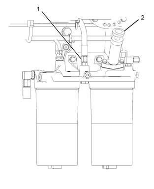
Illustration 26
g01288627
To check the fuel transfer pump pressure, remove
the hose assembly (1). Install a pressure gauge, and
start the engine.
Fuel Pressure Readings
The typical fuel pressure of the engine at operating
temperature c an vary. When the engine is under
load, the fuel pressure can be 550 kPa (80 psi).
The performance of the unit injector deteriorates
when the fuel pressure drops below 241 kPa (35 psi).
Illustration 27
Front gear group
(1) Timing marks
(2) Camshaft gear
(3) Adjustable idler gear
(4) Idler gear
(5) Cluster gear
(6) Timing marks
(7) Crankshaft gear
(8) Oil pump gear
g01097754
Low power complaints and erratic operation can
occur in this situation. Check for a plugged fuel filter
or air in the fuel lines as possible causes for these
complaints before replacing fuel system components.
The basis for the correct fuel injection timing and
the v alve mechanism operation is determined by
the alignment of the timing for the front gear group.
Timing marks (1) through timing marks (6) are aligned
in order to provide the c orrect relationship between
the piston movement and the valve movement.
| |||||||||||||||||||||
29
Testing and Adjusting Section
Setting
Backlash
For Camshaft
And Adjustable Idler Gear
Table 7
B
1.
Remove the front cover. Refer to Disassembly and
Assembly, “Housing (front) - Remove”.
Note: Ensure that No. 1 pis ton is at the top center
position. Refer to Systems Operation, Testing and
Adjusting, “Finding Top Center Position for No. 1
Piston”.
Illustration 29
Typical example
Installation of the adjustable idler assembly
(A) Cams haft Alignment tool
(1) Nuts
(3) Bolt
g00294873
3.
Refer to Illustration 29 in order to position Tooling
(A). Move Tooling (A) to the left and to the right.
Lightly tighten nuts (1) and bolt (3). Once the nuts
and the bolt are tightened, lightly tap Tooling (A)
with a rubber mallet on the sides. This will ensure
that the tool is properly seated. Tooling (A) should
be free to move in and out without any binding.
Illustration 28
Typical example
Loosen stub shaft assembly.
(1) Nuts
(2) Stub shaft
g00294872
2.
Remove the adjus table idler gear from stub shaft
(2). Stub shaft (2) is held in position with five nuts
(1) and one bolt. Loosen five nuts (1) and loosen
the one bolt.
Illustration 30
Typical example
Checking backlash
(B) Indicator assembly
(4) Camshaft gear
(5) Idler gear assembly
g00294874
![]() 30
30
Testing and Adjusting Section
KENR6231
4.
5.
6.
7.
Install Tooling (B) on the timing gear housing.
Loosely install the idler gear assembly (5) to the
timing gear housing. When idler gear assembly
(5) is held stationary, the bac klash between
the camshaft gear (4) and the idler gear (5) is
0.216 ± 0.114 mm (0.0085 ± 0.0045 inch).
If necessary, repeat step 2 through step 4 in order
to obtain the proper backlash.
Tighten the nuts and the bolt. Refer to Disassembly
and Assembly, “Gear Group (Front) - Install” for
the correct procedure.
Install the front cover. Refer to Disassembly and
Assembly, “Housing (Front) - Install”.
![]()
![]()
![]()
![]()
![]() KENR6231
KENR6231
31
Testing and Adjusting Section
Air
Inlet
and
Exhaust
Syst em
Air
Inlet and
i02581541
Exhaust System
-
Inspect
A general visual inspection should be made to the air
inlet and exhaust system. Make sure that there are
no signs of leaks in the system.
Table 8
|
Required Tools | |||
|
Tool |
Part Number |
Part Description |
Qty |
|
A |
- |
Differential Pressure Gauge |
1 |
Air Inlet Restriction
There will be a reduction in the performance of the
engine if there is a restriction in the air inlet system.
1. Inspect the engine air cleaner inlet and ducting
in order to ensure that the passageway is not
blocked or collapsed.
2. Inspect the engine air cleaner element. Replace
a dirty engine air cleaner element with a clean
engine air cleaner element.
3. Check for dirt tracks on the clean side of the
engine air cleaner element. If dirt tracks are
observed, contaminants are flowing past the
engine air cleaner element and/or the seal for the
engine air cleaner element.
Hot engine
components
can cause
injury
from
burns.
Before
performing
maintenance
on
the
engine, allow the engine and the components to
cool.
Making contact with a running engine can cause
burns from hot parts and can cause injury from
rotating parts.
When working on an engine that is running, avoid
contact with hot parts and rotating parts.
4. Use Tooling (A) for this test.

![]()
![]()
![]()
![]() 32
32
Testing and Adjusting Section
KENR6231
Illustration 31
Air inlet piping
(1) Air Cleaner
(2) Test location
(3) Turbocharger
g01293044
a.
Connect the v acuum port of the differential
pressure gauge to test location (2). Test
location (2) may be located anywhere along the
air inlet piping after air cleaner (1) but before
turbocharger (3).
Maximum restriction ........ 6.2 kPa (25 in of H2O)
The air flow through a new engine air cleaner element
must not have a restriction of more than the following
amount:
Maximum restriction ........ 3.7 kPa (15 in of H2O)
b. Leave the pressure port of the differential
pressure gauge open to the atmosphere.
c. Start the engine. Run the engine at full load.
d. Record the value.
e. Compare the result from step 4.d to the
appropriate values that follow.
The air flow through a used engine air cleaner
may have a restriction. The air flow through a
Turbocharger - Inspect
Hot engine components can cause
i02551491
injury from
plugged engine air cleaner will be restricted to some
burns.
Before
performing
maintenance
on
the
magnitude. In either case, the restriction must not be
more than the following amount:
engine, allow the engine and the components to
cool.
![]()
![]()
![]()
![]() KENR6231
KENR6231
33
Testing and Adjusting Section
Personal injury can result from rotating and mov-
ing parts.
Stay clear of all rotating and moving parts.
Never attempt adjustments while the machine is
moving or the engine is running unless otherwise
specified.
The machine must be parked on a level surface
and the engine stopped.
NOTICE
Keep all parts clean from contaminants.
Contaminants may cause rapid wear and shortened
component life.
NOTICE
Care must be taken to ensure that fluids are contained
during performance of inspection, maintenance, test-
ing, adjusting and repair of the product. Be prepared to
collect the fluid with suitable containers before open-
ing any compartment or disassembling any compo-
nent containing fluids.
Dispose of all fluids according to local regulations and
mandates.
Before you begin inspection of the turbocharger,
be sure that the inlet air restriction is within the
specifications for your engine. Be sure that the
exhaust system restriction is within the specifications
for your engine. Refer to Systems Operation, Testing
and Adjusting, “Air Inlet and Exhaust System -
Inspect”.
The condition of the turbocharger will have definite
effects on engine performance. Use the following
inspections and procedures to determine the
condition of the turbocharger.
• Inspection of the Compressor and the Compressor
Housing
• Inspection of the Turbine Wheel and the Turbine
Housing
1.
2.
3.
4.
Inspect the compressor wheel for damage from a
foreign object. If there is damage, determine the
source of the foreign object. As required, clean
the inlet system and repair the intake system.
Replace the turbocharger. If there is no damage,
go to Step 3.
Clean the compressor wheel and clean the
compressor housing if you find buildup of foreign
material. If there is no buildup of foreign material,
go to Step 3.
Turn the rotating assembly by hand. While you
turn the assembly, push the assembly sideways .
The assembly should turn freely. The compressor
wheel should not rub the compress or housing.
Replace the turbocharger if the compressor wheel
rubs the compressor wheel housing. If there is no
rubbing or scraping, go to Step 4.
Inspect the compressor and the compressor
wheel housing for oil leakage. An oil leak from
the compressor may deposit oil in the aftercooler.
Drain and c lean the aftercooler if you find oil in
the aftercooler.
a. Check the oil level in the crankcase. If the oil
level is too high, adjust the oil level.
b. Inspect the air cleaner element for restriction. If
restriction is found, correct the problem.
c. Inspect the engine crankcase breather. Clean
the engine crankcase breather or replace
the engine crankcase breather if the engine
crankc ase breather is plugged.
d. Remove the oil drain line for the turbocharger.
Inspect the drain opening. Inspect the oil drain
line. Inspect the area between the bearings of
the rotating assembly shaft. Look for oil sludge.
Inspect the oil drain hole for oil sludge. Inspect
the oil drain line for oil sludge in the drain
line. If neces sary, clean the rotating assembly
shaft. If necessary, clean the oil drain hole. If
necessary, clean the oil drain line.
e. If Steps 4.a through 4.d did not reveal the
source of the oil leakage, the turbocharger has
internal damage. Replace the turbocharger.
Inspection of the Compressor and
the Compressor Housing
Remove air piping from the compressor inlet.
Inspection of the Turbine Wheel
and the Turbine Housing
Remove the air piping from the turbine housing.
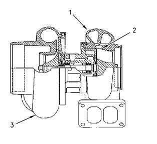
| |||||||||||||
Testing and Adjusting Section
KENR6231
a.
Remove the oil drain line for the turboc harger.
Inspect the drain opening. Inspect the area
between the bearings of the rotating assembly
shaft. Look for oil s ludge. Inspect the oil drain
hole for oil sludge. Inspect the oil drain line
for oil sludge. If necessary, clean the rotating
assembly shaft. If necessary, clean the drain
opening. If necessary, clean the drain line.
Illustration 32
Typical example
(1) Turbine Housing
(2) Turbine Wheel
(3) Turbocharger
g00763164
b. If crankcase pressure is high, or if the oil drain
is restricted, pressure in the center housing
may be greater than the pressure of turbine
housing (1). Oil flow may be forced in the wrong
direction and the oil may not drain. Check the
crankc ase pressure and correct any problems.
c. If the oil drain line is damaged, replace the oil
drain line.
d. Check the routing of the oil drain line. Eliminate
any sharp restrictive bends. Make sure that
the oil drain line is not too close to the engine
exhaust manifold.
e. If Steps 4.a through 4.d did not reveal the
source of the oil leakage, turbocharger (3) has
internal damage. Replace turbocharger (3).
1.
2.
3.
4.
Inspect the turbine for damage by a foreign object.
If there is damage, determine the source of the
foreign object. Replace turbocharger (3). If there
is no damage, go to Step 2.
Inspect turbine wheel (2) for buildup of carbon and
other foreign material. Inspect turbine housing (1)
for buildup of carbon and foreign material. Clean
turbine wheel (2) and clean turbine housing (1) if
you find buildup of carbon or foreign material. If
there is no buildup of carbon or foreign material,
go to Step 3.
Turn the rotating assembly by hand. While you
turn the assembly, push the assembly sideways.
The assembly should turn freely. Turbine wheel (2)
should not rub turbine wheel housing (1). Replace
turbocharger (3) if turbine wheel (2) rubs turbine
housing (1). If there is no rubbing or scraping, go
to Step 4.
Inspect the turbine and turbine housing (1) for oil
leakage. Inspect the turbine and turbine housing
(1)for oil coking. Some oil coking may be cleaned.
Heavy oil coking may require replacement of
the turbocharger. If the oil is coming from the
turboc harger center housing go to Step 4.a.
Otherwise go to “Inspection of the Wastegate”.
i02571444
Exhaust Temperature - Test
Table 9
When the engine runs, the temperature of an exhaust
manifold port can indicate the condition of a fuel
injection nozzle.
A low temperature indicates that no fuel is flowing to
the cylinder. An inoperative fuel injection nozzle or
a problem with the fuel injection pump could caus e
this low temperature.
A very high temperature can indicate that too much
fuel is flowing to the cylinder. A malfunctioning
fuel injection nozzle could cause this very high
temperature.
Use the Tooling (A) to check exhaust temperature.
![]()
![]()
| |||||||||||||
| ||||||||||||||||
35
Testing and Adjusting Section
Engine
Crankcase
i02571687
Pressure
This engine uses high voltage to control the fuel
(Blowby) - Test
Table 10
Damaged pistons or rings can cause too much
pressure in the crankcase. This condition will cause
the engine to run rough. There will be more than the
normal amount of fumes (blowby) rising from the
crankcase breather. The breather can then become
restricted in a very short time, causing oil leakage
at gaskets and seals that would not normally have
leakage. Blowby can also be caused by worn valve
guides or by a failed turbocharger seal.
Install Tooling (A) to the most convenient location on
the output tube for the crankcase breather or the
breather hose. The pressure for the engine blowby
should be 0.25 kPa (1 inch of H2O).
Note: Do not use the data alone to determine if the
engine should be overhauled. Other indicators such
as high oil consumption, low power, hard starting,
and excessive fuel cons umption must be considered.
After a new engine is used for a short time, the
blowby can decrease as the rings are seated. New
engines should be checked for blowby during all
maintenance checks. As the piston rings and cylinder
walls wear, the blowby will gradually increase.
The blowby on a worn engine may be two times or
more than the blowby of a new engine and may
indicate the need for an overhaul.
injectors.
Disconnect electronic fuel injector enable circuit
connector to prevent personal injury.
Do not come in contact with the fuel injector ter-
minals while the engine is running.
Note: Valve lash is measured between the rock er
arm and the valve bridge. All measurements and
adjustments must be made with the engine stopped
and the valves fully closed.
Valve Lash Check
An adjustment is NOT NECESSARY if the
measurement of the valve lash is in the acceptable
range in Table 11.
Table 11
(1) 360° from TC compression stroke
(2) The No. 1 cylinder is at the front of the engine.
If the measurement is not within this range, an
adjustment is necessary. Refer to “Valve Lash
Adjustment” for the proper procedure.
Engine
Valve
Lash
-
i02553372
Inspect/Adjust
To prevent possible injury, do not use the starter
to turn the flywheel.
Hot engine components can cause burns. Allow
additional time for the engine to cool before mea-
suring valve clearance.
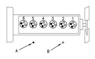
|
|
Testing and Adjusting Section
KENR6231
Valve Lash Adjustment
Note: If necessary, adjust the electronic unit injectors
on cylinders 3, 5 and 6. Refer to Systems Operation,
Testing and Adjusting, “Electronic Unit Injector -
Adjust” for the correct procedure.
3. Remove the timing pin. Turn the flywheel by 360
degrees in the direction of engine rotation. This
will put the No. 6 piston at the top center position
on the compression stroke. Install the timing pin.
Table 13
Illustration 33
Cylinder and valve loc ation
(A) Exhaust valves
(B) Inlet valves
g00935559
4.
Adjust the valve lash according to Table 13.
Use the following procedure to adjust the valve lash:
1. Put the No. 1 piston at the top center position
on the compress ion stroke. Refer to Systems
Operation, Testing and Adjusting, “Finding Top
Center Position for No. 1 Piston”.
a.
Lightly tap the rocker arm with a soft mallet.
This will ensure that the lifter roller seats
against the camshaft’s base circle.
Table 12
2. Adjust the valve lash according to Table 12.
a. Lightly tap the rocker arm with a soft mallet.
This will ensure that the lifter roller seats
agains t the camshaft’s base circle.
b. Loosen the adjustment locknut.
c. Place the appropriate feeler gauge between
5.
b. Loosen the adjustment locknut.
c. Plac e the appropriate feeler gauge between
rocker arm and the valve bridge. Then, turn
the adjustment screw in a cloc kwise direction.
Slide the feeler gauge between the rock er arm
and the valve bridge. Continue turning the
adjustment screw until a slight drag is felt on
the feeler gauge. Remove the feeler gauge.
d. Tighten the adjustment locknut to a torque
of 30 ± 7 N·m (22 ± 5 lb ft). Do not allow
the adjustment screw to turn while you are
tightening the adjustment locknut. Recheck
the valve lash after tightening the adjustment
locknut.
Remove the timing bolt from the flywheel after all
adjustments to the valve lash have been made.
Reinstall the timing cover.
rocker arm and the valve bridge. Then, turn
the adjustment screw in a clockwise direction.
Slide the feeler gauge between the rocker arm
and the valve bridge. Continue turning the
adjustment screw until a slight drag is felt on
the feeler gauge. Remove the feeler gauge.
d. Tighten the adjustment locknut to a torque
of 30 ± 7 N·m (22 ± 5 lb ft). Do not allow
the adjustment screw to turn while you are
tightening the adjustment locknut. Recheck
the valve lash after tightening the adjustment
locknut.
Refer to Systems Operation, Testing and Adjusting,
“Electronic Unit Injector - Adjust”.
![]()
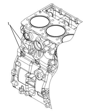
![]()
![]()
| |||||||||||||
37
Testing and Adjusting Section
Lubricati on
System
Engine Oil Pressure - Test
i02571670
The engine oil pressure may be checked
electronically by using the electronic service tool.
The engine oil pressure can be measured with the
electronic service tool. Refer to Troubleshooting for
information on the use of the electronic serv ice tool.
Measuring Engine Oil Pressure
Work carefully around an engine that is running.
Engine parts that are hot, or parts that are moving,
can cause personal injury.
NOTICE
Keep all parts clean from contaminants.
Contaminants may cause rapid wear and shortened
component life.
NOTICE
Illustration 34
Oil gallery plug
(1) Plug
g00977330
Care must be taken to ensure that fluids are contained
during performance of inspection, maintenance, test-
1.
Install Tool (A) into the oil gallery plugs (1).
ing, adjusting and repair of the product. Be prepared to
collect the fluid with suitable containers before open-
ing any compartment or disassembling any compo-
nent containing fluids.
Dispose of all fluids according to local regulations and
mandates.
Table 14
Tool (A) measures the oil pressure in the system.
Note: Engine oil pressure to the camshaft and main
bearings should be checked on each side of the
cylinder block at oil gallery plugs (1).
2. Start the engine. Refer to Operation and
Maintenance Manual, “Refill Capacities and
Rec ommendations” for the recommendations of
engine oil.
3. Rec ord the value of the engine oil pressure when
the engine is at operating temperature 100 °C
(212 °F).
The minimum engine oil pressure should be
approximately 275 to 414 kPa (40 to 59 psi).
4. Compare the recorded engine oil pressure with
the oil pressure indicators on the instrument panel
and the engine oil pressure that is displayed on
the electronic service tool.
5. An engine oil pressure indicator that has a defect
or an engine oil press ure sensor that has a defect
can give a false indication of a low oil pressure or
a high oil pressure. If there is a notable difference
between the engine oil pressure readings make
necessary repairs.
![]()
![]()
![]() 38
38
Testing and Adjusting Section
KENR6231
6.
7.
If low engine oil pressure is determined, refer to
“Reasons for Low Engine Oil Pressure”.
If high engine oil pressure is determined, refer to
“Reason for High Engine Oil Pressure”.
2.
Engine oil that is contaminated with fuel or coolant
will cause low engine oil pressure. High engine
oil level in the crankcase can be an indication
of contamination. Determine the reason for
contamination of the engine oil and make the
necessary repairs. Replace the engine oil with the
approved grade of engine oil. Refer to Operation
Reasons
Pressure
for
Low
Engine
Oil
and Maintenance Manual, “Engine Oil” for the
recommendations of engine oil.
|
|
|
|
Keep all parts clean from contaminants.
Contaminants may cause rapid wear and shortened
component life.
NOTICE
Care must be taken to ensure that fluids are contained
during performance of inspection, maintenance, test-
ing, adjusting and repair of the product. Be prepared to
collect the fluid with suitable containers before open-
ing any compartment or disassembling any compo-
nent containing fluids.
Dispose of all fluids acc ording to local regulations and
mandates.
• Engine oil level is low. Refer to Step 1.
• Engine oil is contaminated. Refer to Step 2.
Step 3.
Step 4.
screen. Refer to Step 5.
• The engine oil pump is faulty. Refer to Step 6.
to Step 7.
1. Check the engine oil level in the crankcase. The
oil level can possibly be too far below the oil pump
supply tube. This will cause the oil pump not to
have the ability to supply enough lubrication to the
engine components. If the engine oil level is low
add engine oil in order to obtain the correct engine
oil level. Refer to Operation and Maintenance
Manual, “Engine Oil” for the recommendations of
engine oil.
NOTICE
Perkins oil filters are manufactured to Perkins speci-
fications. Use of an oil filter that is not recommended
by Perkins c ould result in severe damage to the en-
gine bearings, crankshaft, etc., as a result of the larger
waste particles from unfiltered oil entering the engine
lubricating system. Only use oil filters recommended
by Perkins.
3. If the engine oil bypass valves are held in the
open position, a reduc tion in the oil pressure can
be the result. This may be due to debris in the
engine oil. If the engine oil bypass valves are
stuck in the open position, remove each engine
oil by pass valve and clean each bypass valve
in order to correct this problem. You must also
clean each bypass valve bore. Install new engine
oil filters. New engine oil filters will prevent more
debris from causing this problem. For information
on the repair of the engine oil bypass valves, refer
to Disassembly and Assembly, “Engine Oil Filter
Base - Disassemble”.
4. An oil line or an oil passage that is open, broken,
or disconnected will cause low engine oil pressure.
An open lubrication system could be caused by
a piston cooling jet that is missing or damaged.
Determine the reason for an open lubrication
system of the engine and make the necessary
repairs.
Note: The piston cooling jets direct engine oil toward
the bottom of the piston in order to cool the piston.
This also provides lubrication for the piston pin.
Breakage, a restriction or incorrect installation of the
piston cooling jets will cause seizure of the piston.
5. The inlet screen of the oil pickup tube for the
engine oil pump can have a restriction. This
restriction will cause cavitation and a loss of
engine oil pres sure. Check the inlet screen on
the oil pickup tube and remove any material that
may be restricting engine oil flow. Low engine oil
pressure may also be the result of the oil pickup
tube that is drawing in air. Check the joints of the
oil pickup tube for cracks or a damaged O-ring
seal. Remove the engine oil pan in order to gain
access to the oil pickup tube and the oil screen.
Refer to Disassembly and Assembly, “Engine Oil
Pan - Remove and Install” for more information.
![]()
![]()
![]()
![]() KENR6231
KENR6231
39
Testing and Adjusting Section
6.
7.
Check the following problems that may occur to
the engine oil pump.
a. Air leakage in the supply side of the oil pump
will also cause cavitation and loss of oil
pressure. Check the supply side of the oil pump
and make necessary repairs. For information
on the repair of the engine oil pump, refer to
Disassembly and Assembly, “Engine Oil Pump
- Remove”.
b. Oil pump gears that have too much wear will
cause a reduction in oil pressure. Repair the
engine oil pump. For information on the repair
of the engine oil pump, refer to Disassembly
and Assembly, “Engine Oil Pump - Remove”.
Excessive clearance at engine bearings will
cause low engine oil pressure. Check the
engine components that have excessive bearing
clearance and make the necessary repairs.
NOTICE
Perkins oil filters are manufactured to Perkins speci-
fications. Use of an oil filter that is not recommended
by Perkins c ould result in severe damage to the en-
gine bearings, crankshaft, etc., as a result of the larger
waste particles from unfiltered oil entering the engine
lubricating system. Only use oil filters recommended
by Perkins.
i02553373
Excessive Bearing Wear -
Inspect
When some components of the engine show bearing
wear in a short time, the cause can be a restriction in
an oil passage.
Reason
for High
Engine
Oil
An engine oil pressure indicator may show that there
is enough oil pressure, but a component is worn
Pressure
NOTICE
due to a lack of lubrication. In such a case, look at
the passage for the oil supply to the component.
A restriction in an oil supply passage will not allow
Keep all parts clean from contaminants.
Contaminants may cause rapid wear and shortened
component life.
NOTICE
Care must be taken to ensure that fluids are contained
during performance of inspection, maintenance, test-
ing, adjusting and repair of the product. Be prepared to
collect the fluid with suitable containers before open-
ing any compartment or disassembling any compo-
nent containing fluids.
Dispose of all fluids according to local regulations and
mandates.
Engine oil pressure will be high if the engine oil
bypass valves become stuck in the closed position
and the engine oil flow is restricted. Foreign matter
in the engine oil system could be the cause for the
restriction of the oil flow and the movement of the
engine oil bypass valves. If the engine oil bypass
valves are stuck in the closed position, remove
each bypass valve and clean each bypass valve in
order to correct this problem. You must also clean
each bypass valve bore. Install new engine oil
filters. New engine oil filters will prevent more debris
from causing this problem. For information on the
repair of the engine oil filter bypass valve, refer to
Disassembly and Assembly, “Engine Oil Filter Base -
Disassemble”.
enough lubrication to reach a component. This will
result in early wear.
i02553374
Excessive Engine Oil
Consumption - Inspect
Engine Oil Leaks on the Outside of
the Engine
Check for leakage at the seals at each end of the
crankshaft. Look for leak age at the gasket for the
engine oil pan and all lubrication system connections.
Look for any engine oil that may be leaking from
the crankcase breather. This can be caused by
combus tion gas leakage around the pistons. A dirty
crankcase breather will cause high pressure in the
crankcase. A dirty crankcase breather will cause the
gaskets and the seals to leak.
Engine Oil Leaks into the
Combustion Area of the Cylinders
Engine oil that is leaking into the combustion area of
the cylinders can be the cause of blue s moke. There
are several possible way s for engine oil to leak into
the combustion area of the c ylinders:
• Leaks between worn valve guides and valve stems
![]() 40
40
Testing and Adjusting Section
KENR6231
•
•
•
•
•
Worn components or damaged components
(pistons, piston rings, or dirty return holes for the
engine oil)
Incorrect installation of the compression ring and/or
the intermediate ring
Leaks past the seal rings in the turbocharger shaft
Overfilling of the crankcase
Wrong dipstick or guide tube
Excessive consumption of engine oil can also
result if engine oil with the wrong viscosity is used.
Engine oil with a thin viscosity can be caused by fuel
leakage into the crankcase or by increased engine
temperature.
Increased
Engine
Oil
i02553375
Temperature
- Inspect
If the oil temperature is high, then check for a
restriction in the oil pas sages of the oil cooler. A
restriction in the oil cooler will not cause low oil
pressure in the engine.
Determine if the oil cooler bypass valve is held in the
open position. This condition will allow the oil to pass
through the v alve instead of the oil cooler. The oil
temperature will increase.
Refer to Operation and Maintenance Manual, “Refill
Capacities” for the correct lubricating oil.
![]()
![]() KENR6231
KENR6231
41
Testing and Adjusting Section
Cooling
System
i02553376
5.
Check the sending unit. In some conditions, the
temperature sensor in the engine sends signals
to a sending unit. The sending unit converts these
signals to an electrical impulse which is used by a
mounted gauge. If the sending unit malfunctions,
Cooling
System - Check
the gauge can show an incorrect reading. Also if
the electric wire breaks or if the electric wire shorts
(Overheating)
Above normal coolant temperatures can be caused
by many conditions. Use the following procedure
to determine the cause of above normal coolant
temperatures:
Personal injury can result from escaping fluid un-
der pressure.
If a pressure indication is shown on the indicator,
push the release valve in order to relieve pressure
before removing any hose from the radiator.
1. Check the coolant level in the cooling system.
Refer to Operation and Maintenance Manual,
“Cooling System Coolant Level - Check”. If the
coolant level is too low, air will get into the cooling
system. Air in the cooling system will cause a
reduction in coolant flow and bubbles in the
coolant. Air bubbles will keep coolant away from
the engine parts, which will prevent the transfer of
heat to the coolant. Low coolant level is caused by
leaks or incorrectly filling the radiator.
2. Check the mixture of antifreeze and water. Refer
to Operation and Maintenance Manual, “Fluid
Recommendations”. If the coolant mixture is
incorrect, drain the s ystem. Put the correct mixture
of water, antifreeze and coolant conditioner in the
cooling system.
3. Check for air in the cooling system. Air can enter
the cooling system in different ways. The most
common causes of air in the cooling system
are not filling the cooling system correctly and
combustion gas leakage into the cooling system.
Combustion gas can get into the system through
ins ide cracks, a damaged cylinder head, or a
damaged cylinder head , ga, sket. Air in the c ooling
system c auses a reduction in coolant flow and
bubbles in the coolant. Air bubbles keep coolant
away from the engine parts, which prevents the
transfer of heat to the coolant.
4. Check the water temperature gauge. A water
temperature gauge which does not work correctly
will not show the correct temperature. Refer
to Systems Operation, Testing and Adjusting,
“Cooling System - Inspect”.
6.
7.
8.
9.
out, the gauge can show an incorrect reading.
Check the radiator.
a. Check the radiator for a restriction to coolant
flow. Check the radiator for debris, dirt, or
deposits on the inside of the radiator core.
Debris, dirt, or deposits will restrict the flow of
coolant through the radiator.
b. Check for debris or damage between the fins
of the radiator core. Debris between the fins
of the radiator core restricts air flow through
the radiator core. Refer to Systems Operation,
Testing and Adjusting, “Cooling System -
Inspect”.
c. Ensure that the radiator size is adequate for
the application. An undersized radiator does
not have enough area for the effective release
of heat. This may cause the engine to run
at a temperature that is higher than normal.
The normal temperature is dependent on the
ambient temperature.
Check the filler c ap. A pressure drop in the
radiator can cause the boiling point to be lower.
This can cause the cooling system to boil. Refer
to Systems Operation, Testing and Adjusting,
“Cooling System - Tes t”.
Check the fan and/or the fan shroud.
a. The fan must be large enough to send air
through most of the area of the radiator core.
Ensure that the size of the fan and the position
of the fan are adequate for the application.
b. The fan shroud must be the proper size and
the fan shroud must be positioned correctly.
Ensure that the size of the fan shroud and the
position of the fan shroud are adequate for the
application.
If the fan is belt driven, check for loose drive belts .
A loose fan drive belt will cause a reduction in the
air flow across the radiator. Check the fan drive
belt for proper belt tension. Adjust the tension of
the fan drive belt, if necessary. Refer to Sys tems
Operation, Testing and Adjusting, “Belt Tension
Chart”.
![]()
![]() 42
42
Testing and Adjusting Section
KENR6231
10. Check the cooling system hoses and clamps.
Damaged hoses with leaks can normally be seen.
Hoses that have no visual leak s can soften during
operation. The soft areas of the hose can become
kinked or crushed during operation. These areas
of the hose can cause a restriction in the coolant
flow. Hoses become soft and/or get cracks
after a period of time. The inside of a hose can
deteriorate, and the loose particles of the hose
can cause a restriction of the coolant flow. Refer
to Operation and Maintenance Manual, “Hoses
and Clamps - Inspect/Replace”.
11. Check for a restriction in the air inlet system.
A restriction of the air that is coming into the
engine can cause high cylinder temperatures.
High cy linder temperatures cause higher than
normal temperatures in the cooling system. Refer
to Systems Operation, Testing and Adjusting, “Air
Inlet and Exhaust System - Inspect”.
a. If the measured restriction is higher than the
maximum permissible restriction, remove the
foreign material from the engine air cleaner
element or install a new engine air cleaner
element. Refer to Operation and Maintenance
Manual, “Engine Air Cleaner Element -
Clean/Replace”.
b. Check for a restriction in the air inlet system
again.
c. If the measured restriction is still higher than
the maximum permissible restriction, check the
air inlet piping for a restriction.
12. Check for a restriction in the exhaust system.
A restriction of the air that is coming out of the
engine can cause high cylinder temperatures.
a. Make a visual inspection of the exhaust system.
Check for damage to exhaust piping or for a
damaged muffler. If no damage is found, check
the exhaust system for a restriction. Refer to
Systems Operation, Testing and Adjusting, “Air
Inlet and Exhaust System - Inspect”.
b. If the measured restriction is higher than the
maximum permissible restriction, there is a
restriction in the exhaust system. Repair the
exhaust system, as required.
13. Check the shunt line, if the shunt system is
used. The shunt line must be submerged in the
expansion tank. A restriction of the shunt line
from the radiator top tank to the engine water
pump inlet will cause a reduction in water pump
efficiency. A reduction in water pump efficiency
will result in low coolant flow and overheating.
14. Chec k the water temperature regulator. A water
temperature regulator that does not open, or
a water temperature regulator that only opens
part of the way can cause overheating. Refer to
Systems Operation, Testing and Adjusting, “Water
Temperature Regulator - Test”.
15. Check the water pump. A water pump with a
damaged impeller does not pump enough coolant
for correct engine cooling. Remove the water
pump and check for damage to the impeller. Refer
to Systems Operation, Testing and Adjusting,
“Water Pump - Test”.
16. Chec k the air flow through the engine
compartment. The air flow through the radiator
comes out of the engine compartment. Ensure
that the filters, air conditioner, and similar items
are not installed in a way that prevents the free
flow of air through the engine compartment.
17. Chec k the aftercooler. A restriction of air flow
through the air to air aftercooler (if equipped) can
cause overheating. Check for debris or deposits
which would prevent the free flow of air through
the aftercooler.
18. Cons ider high outside temperatures. When
outside temperatures are too high for the rating
of the cooling system, there is not enough of a
temperature difference between the outside air
and coolant temperatures.
19. Cons ider high altitude operation. The cooling
capacity of the cooling system goes down as
the engine is operated at higher altitudes. A
pressurized cooling s ystem that is large enough to
keep the coolant from boiling must be used.
i02553378
Cooling System - Inspect
Cooling systems that are not regularly inspected are
the cause for increased engine temperatures. Make
a visual inspection of the cooling system before any
tests are performed.
Personal injury can result from escaping fluid un-
der pressure.
If a pressure indication is shown on the indicator,
push the release valve in order to relieve pressure
before removing any hose from the radiator.
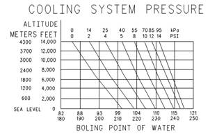
![]()
![]()
![]()
![]() KENR6231
KENR6231
43
Testing and Adjusting Section
1.
2.
Check the coolant level in the cooling system.
Refer to Operation and Maintenance Manual,
“Cooling System Coolant Level - Check”.
Check the quality of the coolant. The coolant
should have the following properties:
• Color that is similar to new coolant
• Odor that is similar to new coolant
• Free from dirt and debris
If the coolant does not have these properties,
drain the sy stem and flush the system. Refill
the cooling system with the correct mixture of
water, antifreeze, and coolant conditioner. Refer
to Operation and Maintenance Manual, “Fluid
Illustration 35
Boiling point of water
g00921815
3.
Recommendations”.
Look for leak s in the system.
Remember that temperature and pressure work
together. When a diagnosis is made of a cooling
system problem, temperature and pressure must be
checked. Cooling system pressure will have an effec t
on the cooling system temperature. For an example,
Note: A small amount of coolant leak age across
the surfac e of the water pump seals is normal. This
leakage is required in order to provide lubrication for
this type of seal. A hole is provided in the water pump
housing in order to allow this coolant/seal lubric ant
to drain from the pump housing. Intermittent leakage
of small amounts of coolant from this hole is not an
indication of water pump seal failure.
4. Ensure that the air flow through the radiator does
not have a restriction. Look for bent core fins
between the folded cores of the radiator. Also, look
for debris between the folded cores of the radiator.
5. Inspect the drive belts for the fan.
6. Check for damage to the fan blades.
7. Look for air or combustion gas in the cooling
system.
8. Inspect the filler cap, and check the surface that
seals the filler cap. This surface must be clean.
i02553379
Cooling System - Test
This engine has a pres sure type cooling system. A
pressure type cooling system has two advantages.
The cooling system can be operated in a safe manner
at a temperature higher than the normal boiling point
(steam) of water.
This type of system prevents cavitation in the water
pump. Cavitation is the forming of low pressure
bubbles in liquids that are caused by mechanical
forces. It is difficult to create a pocket of air in this
type of cooling system.
refer to Illustration 35. This will show the effect of
pressure on the boiling point (steam) of water. This
will also show the effect of height above s ea level.
Personal injury can result from hot coolant, steam
and alkali.
At operating temperature, engine coolant is hot
and under pressure. The radiator and all lines
to heaters or the engine contain hot coolant or
steam. Any contact can cause severe burns.
Remove filler cap slowly to relieve pressure only
when engine is stopped and radiator cap is cool
enough to touch with your bare hand.
Cooling System Conditioner contains alkali. Avoid
contact with skin and eyes.
The coolant level must be to the correct level in order
to check the coolant sys tem. The engine must be
cold and the engine must not be running.
After the engine is cool, loosen the pressure cap
in order to relieve the pressure out of the cooling
sys tem. Then remove the pressure c ap.
The level of the coolant should not be more than
13 mm (0.5 inch) from the bottom of the filler pipe. If
the cooling system is equipped with a sight glass,
the coolant should be to the proper level in the sight
glass.
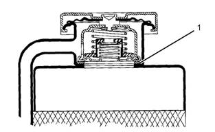
![]()
![]()
| |||||||||||||
| |||||||||||||
Testing and Adjusting Section
KENR6231
Checking the Filler Cap
Table 15
•
•
Seal
Surface for seal
One cause for a pressure loss in the cooling system
can be a damaged seal on the radiator filler cap.
2.
3.
4.
5.
Remove any deposits that are found on these
items, and remove any material that is found on
these items.
Install the filler cap onto Tooling (A).
Look at the gauge for the exact pressure that
opens the filler cap.
Compare the gauge reading with the opening
pressure that is listed on the filler cap.
If the filler cap is damaged, replace the filler c ap.
Testing The Radiator And Cooling
System For Leaks
Table 16
Illustration 36
Typical schematic of filler cap
(1) Sealing surface of both filler cap and radiator
g01096114
Use the following procedure in order to check the
cooling system for leaks:
Personal injury can result from hot coolant, steam
and alkali.
At operating temperature, engine coolant is hot
and under pressure. The radiator and all lines
to heaters or the engine contain hot coolant or
steam. Any contact can cause severe burns.
Remove filler cap slowly to relieve pressure only
when engine is stopped and radiator cap is cool
enough to touch with your bare hand.
Cooling System Conditioner contains alkali. Avoid
contact with skin and eyes.
To check for the amount of pressure that opens the
filler cap, use the following procedure:
1. After the engine cools, carefully loosen the filler
cap. Slowly release the pressure from the cooling
system. Then, remove the filler cap.
Carefully inspect the filler cap. Look for any
damage to the seals and to the sealing surface.
Inspect the following components for any foreign
substances:
• Filler cap
Personal injury can result from hot coolant, steam
and alkali.
At operating temperature, engine coolant is hot
and under pressure. The radiator and all lines
to heaters or the engine contain hot coolant or
steam. Any contact can cause severe burns.
Remove filler cap slowly to relieve pressure only
when engine is stopped and radiator cap is cool
enough to touch with your bare hand.
Cooling System Conditioner contains alkali. Avoid
contact with skin and eyes.
1. After the engine is cool, loosen the filler cap slowly
and allow pressure out of the cooling system.
Then remove the filler cap from the radiator.
2. Ensure that the coolant level is above the top of
the radiator core.
3. Install Tooling (A) onto the radiator.
4. Take the pressure reading on the gauge to 20 kPa
(3 psi) more than the pressure on the filler cap.
![]()
![]()
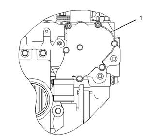
![]()
| |||||||||||||
45
Testing and Adjusting Section
5.
6.
Check the radiator for leakage on the outside.
Check all connection points for leakage, and
check the hoses for leakage.
Coolant temperature can also be read on the display
screens of the Electronic Service Tool.
The cooling system does not have leakage only if the
following conditions exist:.
• You do not observe any outside leakage.
• The reading remains steady after five minutes.
The inside of the cooling system has leakage only if
the following conditions exist:
• The reading on the gauge goes down.
• You do NOT observe any outside leakage.
Make any repairs, as required.
Test For The Water Temperature
Gauge
Table 17
Illustration 37
Typical example
(1) Water manifold assembly
g01096115
Personal injury can result from escaping fluid un-
der pressure.
If a pressure indication is shown on the indicator,
push the release valve in order to relieve pressure
before removing any hose from the radiator.
Remove a plug from water manifold assembly (1).
Install Tooling (A) in the open port:
A temperature indicator of known accuracy can also
be used to make this check.
Start the engine. Run the engine until the temperature
reaches the desired range according to the test
thermometer. If necessary, place a cover over part of
the radiator in order to cause a restriction of the air
flow. The reading on the water temperature indicator
should agree with the test thermometer within the
tolerance range of the water temperature indicator.
Making contact with a running engine can cause
burns from hot parts and can cause injury from
rotating parts.
When working on an engine that is running, avoid
contact with hot parts and rotating parts.
Check the accuracy of the water temperature
Water Temperature
- Test
i02553380
Regulator
indicator or water temperature sensor if you find
either of the following conditions:
• The engine runs at a temperature that is too hot,
but a normal temperature is indicated. A loss of
coolant is found.
• The engine runs at a normal temperature, but a
hot temperature is indicated. No loss of coolant
is found.
Personal injury can result from escaping fluid un-
der pressure.
If a pressure indication is shown on the indicator,
push the release valve in order to relieve pressure
before removing any hose from the radiator.
1. Remove the water temperature regulator from the
engine.
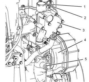
![]()

![]() 46
46
Testing and Adjusting Section
KENR6231
2.
3.
4.
5.
Heat water in a suitable container until the
temperature is 98 °C (208 °F).
Hang the water temperature regulator in the
container of water. The water temperature
regulator must be below the surface of the water
and away from the sides and the bottom of the
container.
Keep the water at the correct temperature for ten
minutes.
After ten minutes, remove the water temperature
regulator. Ensure that the water temperature
regulator is open.
Replace the water temperature regulator if the
water temperature regulator is not open at the
specified temperature. Refer to Specifications,
“Water Temperature Regulator”.
i02553381
Making contact with a running engine can cause
burns from hot parts and can cause injury from
rotating parts.
When working on an engine that is running, avoid
contact with hot parts and rotating parts.
Perform the following procedure in order to determine
if the water pump is operating correctly:
1. Remove the plug from port (2).
2. Install Tooling (A) in port (2).
3. Start the engine. Run the engine until the coolant
is at operating temperature.
4. Note the water pump pres sure. The water pump
pressure should be 100 to 125 kPa (15 to 18 psi).
Water Pump -
Test
Table 18
Tool
A
Required Tools
Part Number Part Description
GE50033 Pressure Gauge
Qty
1
Illustration 38
Typical example
(1) Water outlet
(2) Port
(3) Temperature regulator hous ing
(4) Water pump
(5) Port
g01033819
![]() KENR6231
KENR6231
47
Testing and Adjusting Section
Basic
Engine
i02553382
Connecting rod bearings are available with s maller
inside diameters than the original size bearings.
These bearings are for crankshafts that have been
ground.
Piston
Ring Groove - Inspect
If necessary, replace the connecting rod bearings.
Refer to Disassembly and Assembly, “Connecting
Rod Bearings - Remove” and Disassembly and
Assembly, “Connecting Rod Bearings - Install” for the
correct procedure.
Inspect the Piston and the Piston
Rings
1. Check the piston for wear and other damage.
2. Check that the piston rings are free to move in the
grooves and that the rings are not broken.
Main
Bearings
- Inspect
i02553396
Inspect the Clearance of the Piston
Ring
1. Remove the piston rings and clean the grooves
and the piston rings.
2. Fit new piston rings in the piston grooves.
3. Check the clearance for the piston ring by placing
a suitable feeler gauge between the piston groove
and the top of piston ring. Refer to Specifications,
“Piston and Rings” for the dimensions.
Inspect the Piston Ring End Gap
1. Clean all carbon from the top of the cylinder bores .
2. Place each piston ring in the cylinder bore just
below the cylinder ring ridge.
3. Use a suitable feeler gauge to measure piston
ring end gap. Refer to Specifications, “Piston and
Rings” for the dimensions.
Note: The coil spring must be removed from the oil
control ring before the gap of the oil control ring is
measured.
i02553391
Connecting Rod Bearings -
Inspect
Main bearings are available with smaller inside
diameters than the original size bearings. These
bearings are for crankshafts that have been ground.
If nec essary, replace the main bearings. Refer
to Disassembly and Assembly, “Crankshaft Main
Bearings - Remove and Install” for the correct
procedure.
i02571419
Cylinder Block - Inspect
1. Clean all of the coolant passages and the oil
passages.
2. Check the cylinder block for cracks and damage.
3. The top deck of the cylinder block must not be
machined. This will affect the depth of the cylinder
liner flange and the piston height above the
cylinder block.
4. Check the front cams haft bearing for wear. Refer
to Specifications, “Camshaft Bearings” for the
correct specification of the camshaft bearing. If a
new bearing is needed, use a suitable adapter to
press the bearing out of the bore. Ensure that the
oil hole in the new bearing faces the front of the
block. The oil hole in the bearing must be aligned
with the oil hole in the cylinder block. The bearing
must be aligned with the face of the recess.
The connecting rod bearings fit tightly in the bore in
the rod. If the bearing joints are worn, check the bore
size. This can be an indication of wear because of
a loose fit.

![]()
![]() 48
48
Testing and Ad, just, ing Section
KENR6231
Cylinder
Inspect
Liner
Projection
i02553404
-
Table 19
|
Required Tools | |||
|
Tool |
Part Number |
Part Description |
Qty |
|
A |
GE50005 |
Clamp bolt |
6 |
|
B |
GE50006 |
Clamp washer |
6 |
|
C |
GE50007 |
Fibre washer |
6 |
|
D |
GE50002 |
Cylinder liner projection tool |
1 |
Note: The projection of the cylinder liner is measured
from the top of the cy linder liner to the top of the
spacer plate.
Illustration 39
Liner Projection Components
(1) Bolt
(2) Washer
(3) Washer
(4) Spacer plate
(5) Cylinder liner
(6) Block
g01096458
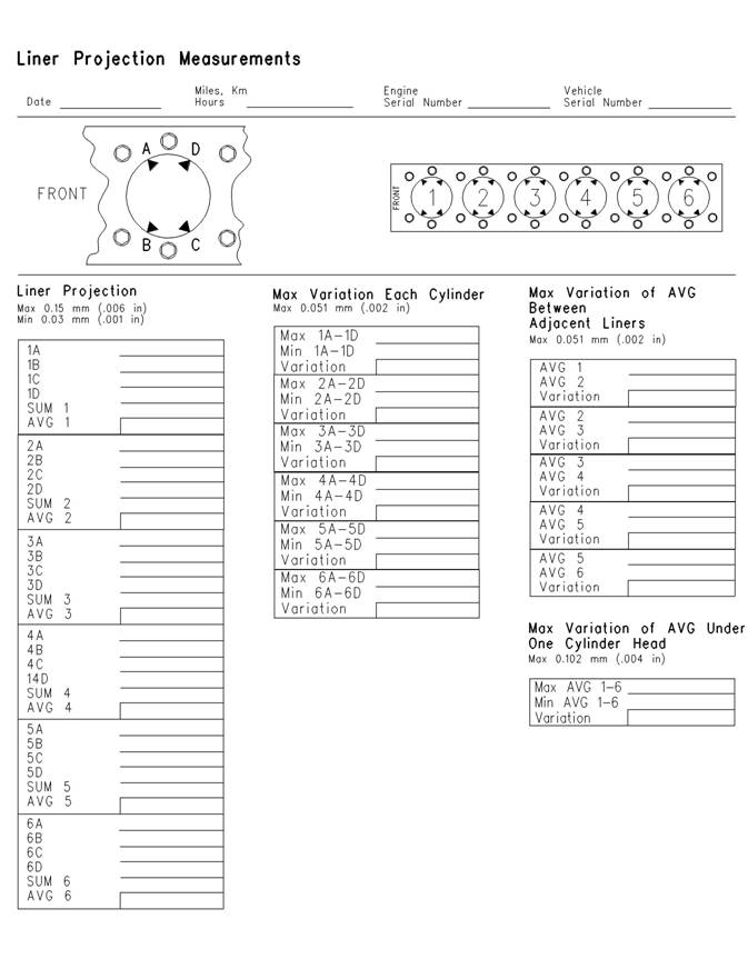
![]() KENR6231
KENR6231
49
Testing and Adjusting Section
Illustration 40
g00443044
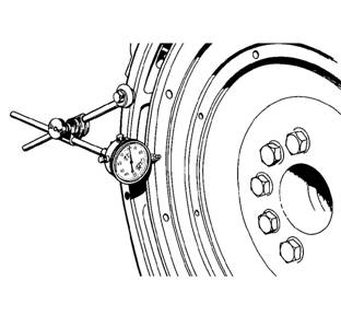
![]() 50
50
Testing and Adjusting Section
KENR6231
1.
2.
3.
4.
5.
6.
7.
8.
9.
Ensure that the top face of the cylinder block (6)
is clean. Install a new s pacer plate gasket and a
clean spacer plate.
Install the cylinder liners to the cylinder block
without seals or bands. Ensure that the cylinder
liners are installed to the original positions.
Install Tooling (B) and Tooling (C) to Tooling (A).
Refer to illustration 39.
Install Tooling (A) around the liner. Refer to
illustration 39.
Tighten the bolts (6) to a torque of 95 N·m (70 lb ft).
Use Tooling (D) to measure the cylinder liner
projection at "A", "B", "C" and "D". Refer to
illustration 40.
Record the measurements for the cylinder.
Repeat steps 3 to 7 for each cylinder.
Add the four readings for each cylinder. Divide the
sum by four in order to find the average.
Do not exceed the maximum liner projection of
0.152 mm (0.006 inch). The excessive liner projection
will contribute to cracking of the liner flange.
When the liner projection is correct, put a temporary
mark on the liner and the spacer plate. Set the liners
aside.
Note: Refer to Disassembly and Assembly, “Cy linder
Liner - Install” for the correct final installation
procedure for the cylinder liners.
i02553516
Flywheel - Inspect
Face Runout (Axial Eccentricity) of
the Flywheel
Table 21
Required Tools
Tool Part Number Part Description Qty
A 21825617 Dial Indicator Group 1
Table 20
|
Specifications | |
|
Liner Projection |
0.025 to 0.152 mm (0.0010 to 0.0060 inch) |
|
Maximum Variation In Each Liner |
0.051 mm (0.0020 inch) |
|
Maximum Average Variation Between Adjacent Liners |
0.051 mm (0.0020 inch) |
|
Maximum Variation Between All Liners |
0.102 mm (0.0040 inch) |
Note: If the liner projection changes around the liner,
turn the liner to a new position within the bore. If the
liner projection is not within specifications, move the
liner to a different bore. Inspect the top face of the
cylinder block.
If the cylinder liner projections are below 0.025 mm
(0.0010 inch) or 0.051 mm (0.0020 inch) corrective
action must be taken. A thinner spacer plate may
be used. The thinner spacer plate is available from
your Perkins distributor. The plates are 0.076 mm
(0.0030 inch) thinner than the original plate. The
Illustration 41
Checking face runout of the flywheel
g00286049
plates will increase the liner projection. Us e these
spacer plates to compensate for low liner projections
which are less than the 0.076 mm (0.0030 inch). Use
these spacer plates if inspection of the top face of
the cylinder block reveals no measurable damage
directly under the liner flanges but the average liner
projection is less than 0.076 mm (0.0030 inch).
1.
2.
Install Tooling (A). Refer to illustration 41. Always
put a force on the crankshaft in the same direction
before the dial indicator is read. This will remove
any crankshaft end clearanc e.
Set the dial indicator to read 0.0 mm (0.00 inch).

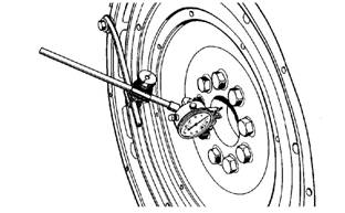

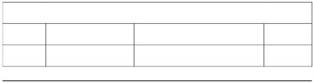
![]()
![]()
![]()
![]() KENR6231
KENR6231
51
Testing and Adjusting Section
3.
4.
Turn the flywheel at intervals of 45 degrees and
read the dial indicator.
Take the measurements at all four points. The
difference between the lower measurements and
the higher measurements that are performed at
all four points must not be more than 0.15 mm
(0.006 inch), which is the maximum permissible
face runout (axial eccentricity) of the flywheel.
Bore
Runout (Radial Eccentricity)
of the Flywheel
Table 22
Required Tools
Tool Part Number Part Description
Qty
Illustration 43
Flywheel clutch pilot bearing bore
g00286058
A
21825617
Dial Indicator Group
1
5.
6.
To find the runout (ec centricity) of the pilot bearing
bore, use the preceding procedure.
The runout (eccentricity) of the bore for the pilot
bearing in the flywheel must not exceed 0.13 mm
(0.005 inch).
i02553531
Flywheel Housing - Inspect
Table 23
|
Required Tools | |||
|
Tool |
Part Number |
Part Description |
Qty |
|
A |
21825617 |
Dial Indicator Group |
1 |
Illustration 42
Checking bore runout of the flywheel
1. Install Tooling (A). Refer to illustration 42.
g01278054
Face Runout (Axial Eccentricity) of
the Flywheel Housing
2.
3.
4.
Set the dial indicator to read 0.0 mm (0.00 inch).
Turn the flywheel at intervals of 45 degrees and
read the dial indicator.
Take the measurements at all four points. The
difference between the lower measurements and
the higher measurements that are performed at
all four points must not be more than 0.15 mm
(0.006 inch) for the maximum permissible face
runout (radial eccentricity) of the flywheel.
Illustration 44
Typical example
g00285931
If you us e any other method except the method that
is given here, always remember that the bearing
clearance must be removed in order to receive the
correct measurements.
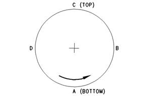
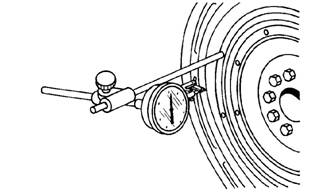

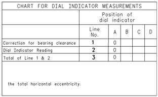
![]()
![]()
![]()
![]()
![]() 52
52
Testing and Adjusting Section
KENR6231
1.
2.
Install Tooling (A) to the fly wheel so the anvil of the
dial indicator will contact the face of the flywheel
housing. Refer to illus tration 44.
Use a rubber mallet and tap the crankshaft toward
the rear before the dial indicator is read at each
point.
Illustration 47
Checking bore runout of the flywheel housing
g00285932
Illustration 45
Checking face runout of the flywheel housing
g00285932
3.
4.
Turn the flywheel while the dial indicator is set at
0.0 mm (0.00 inch) at location (A). Read the dial
indicator at locations (B), (C) and (D).
The difference between the lower measurements
and the higher measurements that are performed
at all four points must not be more than 0.38 mm
(0.015 inch), which is the maximum permissible
face runout (axial eccentricity) of the flywheel
Illustration 48
g00763974
housing.
Bore Runout (Radial Eccentricity)
of the Flywheel Housing
2.
While the dial indicator is in the position at location
(C) adjust the dial indicator to 0.0 mm (0.00 inch).
Push the crankshaft upward against the top of
the bearing. Refer to Illustration 48. Write the
measurement for bearing clearance on line 1 in
column (C).
Illustration 46
Typical example
g00285934
Note: Write the measurements for the dial indicator
with the correct notations. This notation is necessary
for making the calc ulations in the chart correctly.
3. Divide the measurement from Step 2 by two. Write
this number on line 1 in columns (B) and (D).
4. Turn the flywheel in order to put the dial indicator
at position (A). Adjust the dial indicator to 0.0 mm
(0.00 inch).
5. Turn the flywheel counterclockwise in order to
put the dial indicator at position (B). Write the
measurements in the chart.
6. Turn the flywheel counterclockwise in order to
put the dial indicator at position (C). Write the
1.
Install Tooling (A) to the fly wheel so the anvil of the
dial indicator will contact the bore of the flywheel
housing. Refer to illus tration 46.
measurement in the chart.
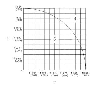
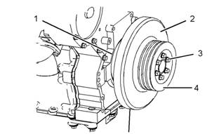
![]()
![]() KENR6231
KENR6231
53
Testing and Adjusting Section
7.
8.
9.
Turn the flywheel counterclockwise in order to
put the dial indicator at position (D). Write the
measurement in the chart.
Add the lines together in each column.
Subtract the smaller number from the larger
number in column B and column D. Place this
number on line III. The result is the horizontal
eccentricity (out of round). Line III in column C is
the vertical eccentricity.
Vibration Damper - Check
i02553546
Illustration 50
(1) Adapter
(2) Vibration damper
(3) Bolts
(4) Crankshaft pulley
g01287000
Illustration 49
Graph for total eccentricity
(1) Total vertical ecc entricity
(2) Total horizontal eccentricity
(3) Acceptable value
(4) Unacceptable value
g00286046
|
|
vibration damper will increase vibrations. This will
result in damage to the crankshaft.
Replace the damper if any of the following conditions
exist:
from the damper.
excessive heat.
• The damper is bent.
10. Find the intersection of the eccentricity lines
(vertical and horizontal) in Illustration 49.
11. If the point of the intersection is in the “Acceptable”
range, the bore is in alignment. If the point of
intersection is in the “Not acceptable” range, the
flywheel hous ing must be c hanged.
•
•
The bolt holes are worn or there is a loose fit for
the bolts.
The engine has had a crankshaft failure due to
torsional forces.
NOTICE
Inspect the viscous vibration damper for signs of leak-
ing and for signs of damage to the case. Either of
these conditions can cause the weight to contact the
case. This contact can affec t damper operation.
![]()
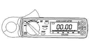
![]()
![]()
![]() 54
54
Testing and Adjusting Section
KENR6231
Ele ct ri ca l
System
i02555153
When it is possible, make a test of the charging
unit and voltage regulator on the engine, and use
wiring and components that are a permanent part of
the system. Off-engine testing or bench testing will
give a test of the charging unit and voltage regulator
Battery -
Test
operation. This testing will give an indication of
needed repair. After repairs are made, perform a test
in order to prove that the units have been repaired to
the original c ondition of operation.
Most of the tests of the electric al system can be done
on the engine. The wiring insulation must be in good
condition. The wire and cable connections must be
clean, and both components must be tight.
Test
Tools
For
The
Charging
System
Never disconnect any charging unit circuit or bat-
tery circuit cable from the battery when the charg-
ing unit is operated. A spark can cause an explo-
sion from the flammable vapor mixture of hydro-
gen and oxygen that is released from the elec-
trolyte through the battery outlets. Injury to per-
sonnel can be the result.
The battery circuit is an electrical load on the charging
unit. The load is variable because of the condition of
the charge in the battery.
NOTICE
The charging unit will be damaged if the connections
Illustration 51
Typical example of an ammeter
g01012117
between the battery and the charging unit are broken
while the battery is being charged. Damage occurs
because the load from the battery is lost and because
there is an increase in charging voltage. High voltage
will damage the charging unit, the regulator, and other
electrical components.
See Special Ins truction, SEHS7633, “Battery Test
Procedure” for the correct procedures to use to
test the battery. This publication also contains the
specifications to use when you test the battery.
i02554905
Charging System - Test
The condition of charge in the battery at each
regular inspection will show if the charging system is
operating correctly. An adjustment is necessary when
the battery is constantly in a low condition of charge
or a large amount of water is needed. A large amount
of water would be more than one ounce of water per
a cell per a week or per every 100 service hours.
The ammeter is a self-contained instrument that
measures electric al currents without breaking
the circuit and without disturbing the conductor’s
insulation.
The ammeter contains a digital display that is used
to monitor current directly within a range between 1
ampere and 1200 amperes. The multimeter should
be used under only one condition:
• the readings are less than 1 ampere.
A lever opens the ammeter’s jaws over a conductor.
The conductor’s diameter can not be larger than
19 mm (0.75 inch).
The spring loaded jaws clos e around the conductor
for measuring the current. A trigger switch controls
the ammeter. The trigger s witch can be locked into
the ON position or into the OFF position.
After the trigger has been working and the trigger is
turned to the OFF position, the reading appears in
the digital display for five seconds. This accurately
measures currents in areas with a limited access.
For example, these areas include areas that are
beyond the operator’s sight. For DC operation, an
ammeter contains a zero control, and batteries inside
the handle supply the power.
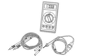
![]()
![]() KENR6231
KENR6231
55
Testing and Adjusting Section
Illustration 52
Typical example of a digital multimeter
g00283566
Electric
Starting
i02554920
System - Test
Most of the tests of the elec trical system can be
done on the engine. The wiring insulation must be
in good c ondition. The wire and cable connections
must be clean, and both components must be tight.
The battery must be fully charged. If the on-engine
test shows a defect in a component, remove the
component for more testing.
The starting system consists of the following four
components:
• Keyswitch
• Start relay
• Starting motor solenoid
• Starting motor
Trouble with the starting system could be caused
by the battery or by charging system problems. If
the battery is suspect, refer to Troubleshooting,
“Battery”. If the starting system is suspect, refer to
Troubleshooting, “Engine Will Not Crank”.
![]() 56
56
Index
Section
KENR6231
Index
A
Air in Fuel - Test..................................................... 23
Air Inlet and Exhaust System .......................... 12, 31
Turbocharger ..................................................... 13
Valves And Valve Mechanism............................ 13
Air Inlet and Exhaust System - Inspect.................. 31
Air Inlet Restriction............................................. 31
B
Basic Engine.................................................... 17, 47
Camshaft............................................................ 18
Crankshaft.......................................................... 18
Cylinder Block Assembly ................................... 17
Cylinder Head Assembly.................................... 18
Pistons, Rings And Connecting Rods ................ 18
Battery - Test ......................................................... 54
Belt Tension Chart ................................................. 22
C
Charging System - Test ......................................... 54
Test Tools For The Charging Sys tem................. 54
Connecting Rod Bearings - Inspect....................... 47
Cooling System ............................................... 16, 41
Cooling System - Check (Overheating) ................. 41
Cooling System - Inspect....................................... 42
Cooling System - Test............................................ 43
Checking the Filler Cap...................................... 44
Test For The Water Temperature Gauge ........... 45
Testing The Radiator And Cooling System For
Leaks................................................................ 44
Cylinder Block - Inspect......................................... 47
Cylinder Liner Projection - Inspect......................... 48
E
Electric Starting System - Test............................... 55
Electrical System............................................. 18, 54
Charging System Components .......................... 19
Engine Electrical System ................................... 19
Grounding Practices .......................................... 18
Starting System Components ............................ 20
Electronic Control System Components .................. 6
Electronic Unit Injector - Adjust ............................. 24
Electronic Unit Injector - Test................................. 24
Engine Crankcase Pressure (Blowby) - Test ......... 35
Engine Oil Pressure - Test..................................... 37
Measuring Engine Oil Pressure ......................... 37
Reason for High Engine Oil Pressure ................ 39
Reasons for Low Engine Oil Pressure............... 38
Engine Valve Lash - Inspect/Adjust ....................... 35
Valve Lash Adjustment ...................................... 36
Valve Lash Check .............................................. 35
Excessive Bearing Wear - Inspect......................... 39
Excessive Engine Oil Consumption - Inspect ........ 39
Engine Oil Leaks into the Combustion Area of the
Cylinders .......................................................... 39
Engine Oil Leaks on the Outside of the Engine .. 39
Exhaust Temperature - Test................................... 34
F
Finding Top Center Position for No. 1 Piston......... 25
Flywheel - Inspect.................................................. 50
Bore Runout (Radial Eccentricity) of the
Flywheel........................................................... 51
Face Runout (Axial Eccentricity) of the
Flywheel........................................................... 50
Flywheel Housing - Inspect ................................... 51
Bore Runout (Radial Eccentricity) of the Flywheel
Housing............................................................ 52
Face Runout (Axial Eccentricity) of the Flywheel
Housing............................................................ 51
Fuel Quality - Test.................................................. 26
Fuel System....................................................... 8, 23
Electronic Unit Injector ........................................ 11
Electronic Unit Injector Mechanism.................... 10
Fuel System Electronic Control Circuit ................ 9
Fuel System - Inspect ............................................ 23
Fuel System - Prime .............................................. 26
Fuel System Pressure - Test ..............., ......, ............ 27
Checking Fuel Pressure..................................... 28
Fuel Pressure Readings .................................... 28
High Fuel Press ure ............................................ 27
Low Fuel Pressure ............................................. 27
G
Gear Group (Front) - Time..................................... 28
Setting Backlash For Camshaft And Adjustable
Idler Gear ......................................................... 29
General Information................................................. 4
Cold Mode Operation........................................... 5
Starting the Engine .............................................. 5
I
Important Safety Information ................................... 2
Increased Engine Oil Temperature - Inspec t ......... 40
L
Lubrication System .......................................... 14, 37
Lubrication System Components ....................... 14
Oil Flow In The Engine....................................... 16
![]() KENR6231
KENR6231
Index
57
Section
M
Main Bearings - Inspect......................................... 47
P
Piston Ring Groove - Inspect................................. 47
Inspect the Clearance of the Piston Ring........... 47
Inspect the Piston and the Piston Rings ............ 47
Inspect the Piston Ring End Gap....................... 47
S
Systems Operation Sec tion ..................................... 4
T
Table of Contents..................................................... 3
Testing and Adjusting ............................................ 22
Testing and Adjusting Section ............................... 22
Turbocharger - Inspect .......................................... 32
Inspection of the Compressor and the Compressor
Housing............................................................ 33
Inspection of the Turbine Wheel and the Turbine
Housing............................................................ 33
V
Vibration Damper - Check ..................................... 53
W
Water Pump - Test ................................................. 46
Water Temperature Regulator - Test ..................... 45
![]() 58
58
Index
Section
KENR6231
![]() KENR6231
KENR6231
Index
59
Section
Copyright © 2005 Perkins Engines Company Limited
All Rights Reserved
Printed in U.K.
400-100-8969 15088860848
0574-26871589 15267810868
0574-26886646 15706865167
0574-26871569 18658287286
