 English
 Espaol
 Franais
 阿拉伯
阿拉伯 中文(简)
中文(简) Deutsch
 Italiano
 Português
 日本
日本 韩国
韩国 български
 hrvatski
 esky
esky Dansk
Dansk Nederlands
 suomi
suomi Ελληνικ
 印度
印度 norsk
norsk Polski
 Roman
Roman русский
 Svenska
威尔信帕金斯奥林匹亚发动机发电机预防性维护保养方法
威尔信帕金斯奥林匹亚发动机发电机预防性维护保养方法
Preventive maintenance
Preventive maintenance periods
These preventive maintenance periods apply to average conditions of operation. Chec k the periods given by
the manufacturer of the equipment in which the engine is installed. Use the periods which are shortest. When
the operation of the engine must conform to the local regulations these periods and procedures may need to
be adapted to ensure correct operation of the engine.
It is good preventive maintenance to check for leakage and loose fasteners at each service.
These maintenance periods apply only to engines that are operated with fuel and lubricating oil which conform
to the specifications given in this handbook.
Schedule
800 Series
The operations which follow must be applied at the interval (hours or months) which occurs first.
A Daily D Every 1 months G Every 5000 hours
B Every 50 hours or 1 months E Every 1000 hours or months
C Every 500 hours or 1 months F Every 3000 hours or months
|
A B |
C D |
E F |
G Operation |
|
l l l l l l l |
l l l l l l l l l l l l l |
l l l l l |
Check the amount of coolant Check the air cleaner service indicator Check the amount of lubricating oil in the sump Drain water/sediment from the primary fuel filter Visual inspection Check battery electrolyte level Drain water/sediment from fuel tank Perform diagnostics check Renew the element of the primary fuel filter Renew the element of the secondary fuel filter Check the specific gravity and the pH value of the coolant Renew the engine lubricating oil (1)() Renew the element of the lubricating oil filter Inspect/adjust/renew the alternator and fan belts Inspect the crankshaft vibration damper Inspect/clean/tighten the earth stud Inspect/renew the coolant hoses, air hoses and hose clips Inspect and, if necessary, clean the exterior of the radiator/charge cooler Inspect the engine mountings Drain and flush the coolant system and renew the coolant mixture Check/adjust the tappet clearances and the electronic unit injectors (3) Check the engine protection devices (3) Renew the thermostats of the coolant system Check/clean/calibrate the engine speed/timing sensors Inspect the turbocharger (3) l Inspect the battery charging alternator (3) l Inspect the starter motor (3) l Inspect the coolant pump |
|
MUST be changed at 50 hour intervals.
(3) By a person who has had the correct training.
 800 Series
How to check the amount of the coolant
Check the coolant level when the engine is stopped and cool.
Warning! On a hot engine release the filler cap carefully as the system will be under pressure.
1 Remove the filler cap from the expansion tank slowly to relieve the pressure.
Maintain the coolant level at the bottom of the filler pipe.
3 Clean the filler cap and check the condition of the filler cap gaskets. Renew the filler cap if the gaskets are
damaged. Fit the filler cap.
Inspect the coolant system for leaks.
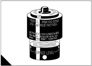
How to check the air cleaner service indicator
Caution: Do not operate the engine if there is a blockage in the air filter or the air duc ts. This can caus e
lubricating oil to enter the cylinders through the engine breather valve.
The air filter is fitted with a restriction indicator (A) which gives a visual warning when the filter needs a service.
When the red warning indicator is s een through the clear panel after the engine has stopped, the air filter
element must be renewed.
After a clean element has been fitted, press the reset button on the res triction indicator.
Environmental conditions have an important effect on the frequency at which the air filter needs to be serviced.
How to check the amount of lubricating oil
800 Series
Warning! Hot oil and hot components can cause personal injury. Do not allow hot oil or hot components to
contact the skin.
At the periods given in the service schedule use the dipstick to check the amount of lubricating oil in the sump.
1 Check the oil level with the engine stopped. The level must be maintained between the “L” mark and “H”
mark on the dipstick.
If necessary, remove the oil filler cap and add more oil of the same grade and specification as that which is
already in the system. Do not overfill.
3 Clean and fit the oil filler cap.
How to drain the primary fuel filter
At the periods given in the service sc hedule, the bowl of the primary fuel filter must be checked and, if
necessary, drained.
1 Open the drain; the drain is self-ventilated. Use a suitable container to collect the water drained from the
filter housing. Dispose of the water safely.
Close the drain. Tighten the drain valve securely to prevent air from entering the fuel system.
00 Series
Visual inspection
A visual inspection should take only a few minutes and can prevent costly repairs and acc idents.
For maximum engine life, ins pect the engine compartment before the engine is started. Look for items such
as oil or coolant leak s, loose fastenings, worn belts or loose connections. Repair as necessary.
The guards must be at the correc t positions. Repair damaged guards or renew missing guards.
Wipe all caps and plugs before the engine is serviced to reduce the chance of system contamination.
For any type of leak (coolant, lubricating oil or fuel), clean away the fluid. If a leak is observed, find the
source and correct the leak. If a leak is suspected, check the fluid levels frequently until the leak is found
and repaired.
Accumulated grease and/or oil on an engine is a fire hazard. Remove it by steam cleaning or by the us e of
a high pressure water jet.
Ensure that the coolant pipes are fitted correctly and that they are secure. Check for leaks. Check the
condition of all pipes.
Inspect the coolant pump for leak s.
Note: The coolant pump seal is lubricated by the coolant in the coolant system. It is normal for a small amount
of leakage to occur as the engine cools and the parts contract.
l Excessive coolant leakage may indicate the need to renew the coolant pump seal. For the removal of the
coolant pump and the installation of the coolant pump and/or coolant pump seals, refer to the Workshop
Manual.
l Inspect the lubrication system for leaks at the front crankshaft seal, the rear crankshaft seal, the sump, the
oil filter and the roc ker cover. If many oil leaks are present, particularly on an old engine, there could be a
blockage of the engine breather.
l Inspect the fuel system for leaks. Check for loose fuel line clamps or for loose ties on the fuel lines.
l Inspect the ducts for the air inlet system and the elbows for cracks. Check also for loose clamps and check
the condition of mounting rubbers. Ensure that hoses and tubes are not in contact with other hoses, tubes,
wiring harnesses, etc.
l Inspect the fan belts and the alternator belt for cracks, breaks or other damage. Where more than one belt
is used between two pulleys, all of the belts must be renewed together. Maximum belt life will only be
obtained if the belts are maintained at the correct tension.
l Drain the water and sediment from fuel tanks on a daily basis to ensure that only clean fuel enters the fuel
system.
l Inspect the wiring and the wiring harnesses for loose connections and for worn or frayed wires.
l Inspect the earth s trap for a good connection and for good condition.
l Inspect the ECM-to-cylinder head earth strap for a good connection and for good condition.
l Disconnect any battery chargers which are not protected against the current drain of the s tarter motor.
Check the condition and the electrolyte level of the batteries, unless the engine is fitted with a maintenance
free battery.
l Check the condition of the gauges. Renew any gauges that are cracked. Renew any gauge that cannot be
calibrated.

Diagnostics check
800 Series
At the periods specified in the s ervice schedule, use the Perkins Electronic Servic e Tool to retrieve the
diagnostic codes. A key to the codes is given below. Refer to the relevant Diagnostic Manual for further details.
Diagnostic codes
CID-FMI
1-11
-11
3-11
-11
5-11
6-11
Injector cylinder No. 1 fault
Injector cylinder No. fault
Injector cylinder No. 3 fault
Injector cylinder No. fault
Injector cylinder No. 5 fault
Injector cylinder No. 6 fault
Diagnostic code description
1-03
1-0
91-08
100-03
100-0
110-03
110-0
168-0
17-03
17-0
17-03
17-0
190-0
190-09
190- 11, 1
8-09
53-0
5-1
61-13
6-03
6-0
68-0
73-03
73-0
7-03
7-0
81-03
81-0
81-05
8-03
8-0
85-03
85-0
86-03
86-0
86-05
33-03
33-0
33-05
8 volt Sensor power supply open/short to B+
8 volt Sensor power supply short to ground
PWM Speed control abnormal
Engine oil pressure sensor open/short to B+
Engine oil pressure sensor short to ground
Engine coolant temp sensor open/short to B+
Engine coolant temp sensor short to ground
Intermittent battery power to the ECM
Intake manifold temperature sensor open/short to B+
Intake manifold temperature sensor short to ground
Fuel temperature sensor open/short to B+
Fuel temperature sensor short to ground
Engine speed sensor data intermittent
Engine speed sensor abnormal update
Engine speed sensor mechanical fault
Perkins data link communications abnormal
Check customer or system parameters
ECM Fault
Engine timing calibration required
5 volt Sensor power supply open/short to B+
5 volt Sensor power supply short to ground
Check programmable parameters
Turbo outlet pressure sensor open/short to B+
Turbo outlet pressure sensor short to ground
Atmospheric pressure sensor open/short to B+
Atmospheric pressure sensor short to ground
Action alert lamp open/short to B+
Action alert lamp short to ground
Action alert lamp open circuit
Engine overspeed lamp open/short to B+
Engine overspeed lamp short to ground
Engine coolant temperature lamp open/short to B+
Engine coolant temperature lamp short to ground
Engine lubricating oil pressure lamp open/short to B+
Engine lubricating oil pressure lamp short to ground
Engine lubricating oil pressure lamp open circuit
Engine shutdown lamp open/short to B+
Engine shutdown lamp short to ground
Engine shutdown lamp open circuit
0
 800 Series
CID-FMI
3-03
3-0
3-05
3-0
3-11, 1
3-03
799-1
166-03
166-0
1690-8
Diagnostic code description
Engine warning lamp open/short to B+
Engine warning l amp short to ground
Engine warning lamp open circuit
Engine speed sensor No. data intermittent
Engine speed sensor No. mechanical fault
Crank terminate relay open/short to B+
Service tool fault
Di agnostic lamp open/short to B+
Di agnostic lamp short to ground
Analogue throttle signal abnormal
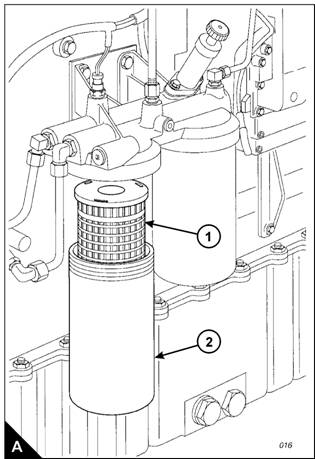

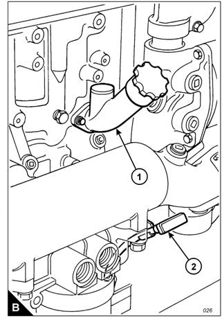
How to renew the element of the primary fuel filter
800 Series
Cautions:
l Do not allow dirt to enter the fuel system. Clean thoroughly the area around a fuel system component that
will be disconnected. Fit a suitable cover to any disconnected component of the fuel system.
l Do not loosen fuel pipes or fittings exc ept where indicated in this handbook.
1 Stop the engine. Turn the start s witch to the “OFF” position. Disconnect the battery.
Close the fuel tank supply valve. Remove the drain plug from the base of the filter housing (A) and drain
the water and fuel into a suitable container. Dispose of the mixture safely.
3 Remove the filter housing, remove the ‘O’ ring seal from the housing and withdraw the filter element (A1).
Warning! Discard the used filter element and ‘O’ ring seal in a safe place and in accordance with local
regulations .
Clean the inside of the housing and the housing thread with clean fuel oil and clean the contact face of the
filter head. Clean the drain plug and fit it to the hous ing.
Notes:
l If a degreasing agent has been used to clean the housing, a special lubricant, CV60896, must be applied
to the threads before the housing is fitted.
l The correct filter element will be marked with the symbol shown (B).
00 Series
5 Fit a new element (A1) into the housing (A), ensure that it engages fully with the guide in the base of the
housing. Fit a new ‘O’ ring seal to the top of the housing.
Cautions:
l It is important that only genuine Perkins parts are used. The use of wrong parts could damage the fuel
injection equipment.
l Do not fill the primary fuel filter with fuel before installation. The fuel would not be filtered and could be
contaminated. Contaminated fuel will c ause accelerated wear to components of the fuel system.
6 Fit the housing onto the filter head. Tighten the housing to a torque of 80 Nm (59 lbf ft). Do NOT overtighten.
Ensure that the drain plug is tightened securely.
7 Clean away any fuel which has been spilled.
8 Open the fuel tank supply valv e and eliminate air from the fuel system as given in "How to eliminate air from
the fuel system" on page 8.
9 Check for leaks.
3
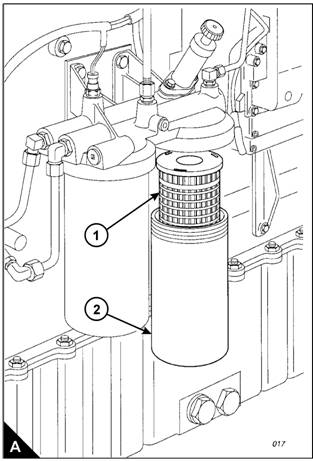
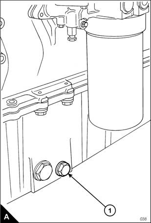
How to renew the element of the secondary fuel filter
800 Series
Cautions:
l Do not allow dirt to enter the fuel system. Clean thoroughly the area around a fuel system component that
will be disconnected. Fit a suitable cover to any disconnected component of the fuel system.
l Do not loosen fuel pipes or fittings exc ept where indicated in this handbook.
1 Stop the engine.
Turn the start switch to the “OFF” position. Disconnect the battery.
3 Close the fuel tank supply valve. Remove the drain plug from the base of the filter housing (A) and drain
the fuel into a suitable container.
Remove the filter housing, remove the ‘O’ ring seal from the housing and withdraw the filter element (A1).
Warning! Discard the used filter element and ‘O’ ring seal in a safe place and in accordance with local
regulations .
5 Clean the inside of the housing and the housing thread with clean fuel oil and clean the contact face of the
filter head. Clean the drain plug and fit it to the hous ing.
Notes:
l If a degreasing agent has been used to clean the housing, a special lubricant, CV60896, must be applied
to the threads before the housing is fitted.
l The correct filter element will be marked with the symbol shown (B).
![]() 800 Series
800 Series
6 Fit a new element (A1) into the housing (A), ensure that it engages fully with the guide in the base of the
housing. Fit a new ‘O’ ring seal to the top of the housing.
Cautions:
l It is important that only genuine parts are used. The use of wrong parts could damage the fuel injection
equipment.
l Do not fill the secondary fuel filter with fuel before installation. The fuel would not be filtered and could be
contaminated. Contaminated fuel will c ause accelerated wear to components of the fuel system.
7 Fit the housing onto the filter head. Tighten the housing to a torque of 80 Nm (59 lbf ft). Do NOT overtighten.
Ensure that the drain plug is tightened securely.
8 Clean away any fuel which has been spilled.
9 Open the fuel tank supply valv e and eliminate air from the fuel system as given in "How to eliminate air from
the fuel system" on page 8.
10 Check for leaks.
5
![]()
How to check the specific gravity of the coolant
800 Series
Warning! Do not remove the radiator cap while the engine is still hot and the system is under pressure
because dangerous hot coolant can be discharged.
Drain some c oolant from the coolant system after the engine has been stopped and before the formation of
sediment. Proceed as follows:
1 For mixtures which contain inhibited ethylene glycol:
l Put a hydrometer, and a reliable thermometer, into the antifreeze mixture and chec k the readings on both
instruments.
l Compare the readings obtained with the chart and adjust the strength of the mixture as necessary.
For mixtures which contain inhibited propylene glycol:
l Open the c over of the refractometer, check that the clear panel is clean and use a small s yringe to apply
three or four drops of the coolant mixture to the clear panel.
l Spread the coolant over the full area of the clear panel and close the cover. Hold the refractometer
horizontally with the clear panel at the top and inspect the sample through the viewer.
l Compare the reading with the c hart in the instructions; adjust the strength of the mixture as necessary.
Caution: The clear panel must be cleaned thoroughly before use. Some of the fluid which was tested earlier
can remain on the clear panel and this will affect the reading of the sample.
Protection against frost is as follows:
Antifreeze/water
(% by volume)
50/50
60/0
Protection down to
![]() 800 Series
800 Series
How to obtain an oil sample
Warning! Hot oil and hot components can cause personal injury. Do not allow hot oil or hot components to
contact the skin.
This operation must only be performed by personnel with the correct training. To avoid contamination of the
oil sample, ensure that the tools and equipment used are clean.
An oil sample kit (part number KRP157), which includes the relevant sample bottles, is available from Perkins
dealers. Certain engines are fitted with an oil sample valve, use the relevant procedure given below.
Engines fitted with an oil sample valve
1 Fit the vented cap to the sample bottle and insert the open end of the tube into the one of the holes in the cap.
Warning! Hot oil under pressure is present at the oil sample valve. Protective clothing must be worn during
this operation. Do not allow hot oil or hot c omponents to contact the skin.
With the engine running at the normal temperature of operation, remove the dust cap from the sample valve
on the engine and insert the nozzle of the tube into the sample valve. Press the nozzle against the valve, the
valve will open and allow the oil to flow. Ensure that the sample bottle remains upright and withdraw the nozzle
when the correct amount of oil is obtained; a mark on the bottle indicates the correc t level for the oil sample.
3 Fit the dust cap to the sample valve.
Remov e the vented cap from the sample bottle and fit the sealed cap. Dispose of the tube, nozzle and vented
cap in accordance with local regulations.
5 Complete the adhesive label and attach it to the sample bottle. Send the oil sample to a reputable oil analysis
laboratory to provide a recommendations report.
Engines without an oil sample valve
1 Run the engine until the normal temperature of operation is achieved, stop the engine and proceed with the
operation immediately.
Use a vacuum pump and a long flexible tube: remove the engine oil dipstick, insert the flexible tube into the
dipstick tube and withdraw the oil sample. Fit the dipstick to the dipstick tube.
3 Complete an adhesive label and attach it to the sample bottle. Send the oil sample to a reputable oil analysis
laboratory to provide a recommendations report.
Ensure that all equipment used is cleaned or, if relevant, disposed of in accordance with local regulations.
7
![]()
How to renew the engine lubricating oil
800 Series
Warning! Hot oil and hot components can cause personal injury. Do not allow hot oil or hot components to
contact the skin.
1 Operate the engine until it is warm, then stop the engine.
A drain plug is fitted to both sides of the sump, remove one of the sump drain plugs (A1) and drain the
lubricating oil into a suitable container. Clean the drain plug and fit a new s ealing washer. Fit the drain plug
and tighten it to a torque of 5 Nm (33 lbf ft).
Warning! Discard the used filter element and used engine oil in a safe place and in accordance with local
regulations .
3 Renew the element of the lubricating oil filter as given in "How to renew the element of the lubricating oil
filter" on page 9.
Clean the area around the oil filler cap (B1) and remove the cap. Fill the sump to the “H” mark on the dipstick
(B) with clean new lubricating oil of the correct grade as given in "Lubricating oil specification" on page 50.
Do NOT overfill.
To prev ent damage to the crankshaft bearings, crank the engine with the fuel OFF. This will fill the oil filters
before the engine is started. Do NOT crank the engine continuously for more than 30 s econds. Ensure that oil
pressure is indicated on the oil pressure gauge, or the service tool, before the engine is started.
5 Operate the engine at low idle speed for two minutes and check for leakage from the oil filter assembly.
6 Stop the engine and allow the oil to drain back to the sump for a minimum of ten minutes. Check the oil level
on the dips tic k and, if necessary, add more oil. The oil level must be between the “L” and “H” marks on the
dipstick.
8
![]() 800 Series
800 Series
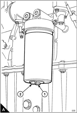
How to renew the element of the lubricating oil filter
1 Stop the engine.
Turn the start switch to the “OFF” position. Disconnect the battery.
3 Remove the drain plug (A) from the base of the oil filter housing (A1) and drain the oil into a suitable
container.
Remove the filter hous ing, remove the ‘O’ ring seal from the housing and withdraw the filter element.
Warning! Discard the used filter element, ‘O’ ring seal and used engine oil in a safe place and in accordance
with local regulations.
5 Clean the housing and clean the contact face of the filter head. Clean the drain plug (A) and fit it to the
housing.
Note: If a degreasing agent has been used to clean the housing, a special lubricant, CV60896, must be applied
to the threads before the housing is fitted.
6 Fit a new element into the housing, ensure that it engages fully with the guide in the base of the housing. Fit
a new ‘O’ ring seal around the top of the housing.
Caution: It is important that only genuine Perkins parts are us ed. The use of incorrect parts could damage the
engine. The correct filter element will be marked with the symbol shown (B).
7 Fit the housing onto the filter head and tighten by use of a socket and torque wrench on the hexagon (A1).
Tighten the housing to a torque of 80 Nm (59 lbf ft). Do NOT overtighten. Ensure that the drain plug is tightened
securely.
8 Check the amount of engine oil in the sump. If necessary, add more oil of the correct grade and specification.
Refer to "Lubricating oil specification" on page 50.
9 Run the engine and check for leaks.
9
![]()
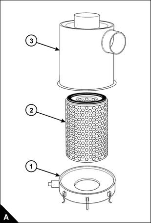
How to renew the air cleaner element
800 Series
The air filter contains a paper element. This must not be washed. Renew the paper element as follows:
1 Loosen the clamp and remove the end cover (A1). Withdraw and discard the filter element (A).
Clean, thoroughly, the inside of the cas ing (A3). Fit a new filter element and fit the end cover.
3 Reset the restriction indicator.
30
![]() 800 Series
800 Series
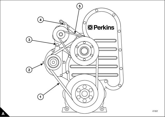
How to check the drive belts
Check all drive belts and renew a belt if it is worn or damaged. Where more than one belt is used between two
pulleys , all of the belts must be renewed together. Maximum belt life will be obtained only if the belts are kept
at the correct tensions. Where more than one belt is used, check/adjust the tension on the tightest belt.
How to adjust the tension of the fan belts
Remove the fan guards and proceed as follows.
Use a Borroughs belt tension gauge. Check the tension at the position shown (A1). It should be 800 N, which
is equivalent to ,0 mm of movement when a force of 33 N is applied. To adjust the tension, proceed as follows:
1 Loosen the lock nuts on the adjustment bolt (A), loosen the large lock nut on the belt tensioner and turn
the adjustment bolt (A) until the correct tension is obtained. Fully tighten the large lock nut and check the
tension of the belts again. If the tension is correct, loosen the adjustment bolt (A) just enough to release its
tension, then tighten its lock nuts.
Fit the fan guards and run the engine for 15 minutes. Remove the guards and check again the tension.
For new fan belts, set the tension to 868 N, which is equivalent to ,0 mm of movement when a force of 35,7 N
is applied. After the engine has been run for 15 minutes, check the tension and adjust it to 800 N; equivalent
to ,0 mm of movement when a force of 33 N is applied.
3 When the correct tension is obtained, fit the fan guards.
31
![]()
How to adjust the tension of the alternator belt
Remove the access panel in the fan guard and proceed as follows.
800 Series
Use a Borroughs belt tension gauge. Check the tension at the position shown (A5). It should be 67 N, which
is equivalent to ,5 mm of movement when a force of 11,3 N is applied. To adjust the tension, proceed as
follows:
1 Loosen the alternator pivot bolt (A3), the adjustment link bolt which is behind the fan pulley and the
adjustment bolt (A). Move the alternator to obtain the correct belt tension and tighten the bolts.
Fit the access panel to the fan guard and run the engine for 15 minutes. Remove the access panel and check
again the tension.
If a new alternator belt is fitted, set the tension to 00 N, which is equivalent to ,5 mm of movement when a
force of 16,6 N is applied. After the engine has been run for 15 minutes, check the tension and adjust it to
67 N; equivalent to ,5 mm of movement when a force of 11,3 N is applied.
3 When the correct tension is obtained, fit the access panel to the fan guard.
3
![]() 800 Series
800 Series
How to renew the fan belts
1 Remove the fan guards.
Remove the six bolts which secure the fan and hub assembly to the pulley and remove the assembly.
Caution: Take care during the removal of the fan; ensure that the radiator does not become damaged.
3 Loosen the belt tensioner and remove the old belts. Ensure that the grooves of the pulley are free from
grease and dirt and fit a new set of belts.
Fit the fan and tighten the bolts securely. Adjust the fan belts to the correct tension, as given in "How to
adjust the tension of the fan belts" on page 31, and fit the fan guards.
How to renew the alternator belt
1 Remove the fan guards.
Remove the six bolts which secure the fan and hub assembly to the pulley and remove the assembly.
Caution: Take care during the removal of the fan; ensure that the radiator does not become damaged.
3 Loosen the adjustment bolts to release the tension on the alternator belt and remov e the old belt. Check that
the pulley grooves are clean and fit a new belt.
Fit the fan and tighten the bolts securely. Adjust the alternator belt to the correct tension, as given in "How
to adjust the tension of the alternator belt" on page 3, and fit the fan guards.
How to inspect the crankshaft vibration damper
The viscous damper has a weight that is located inside a case filled with fluid. The weight moves in the case
to limit torsional v ibration. Inspect the damper for evidence of dents, cracks or leaks of the fluid.
Renew the damper if it is dented, cracked or leaking.
The damper is mounted on the crankshaft and is located behind the belt guard at the front of the engine. Refer
to the Work shop Manual for the correct procedure to remove and to fit the damper.
400-100-8969 15088860848
0574-26871589 15267810868
0574-26886646 15706865167
0574-26871569 18658287286
