 English
 Espaol
 Franais
 阿拉伯
阿拉伯 中文(简)
中文(简) Deutsch
 Italiano
 Português
 日本
日本 韩国
韩国 български
 hrvatski
 esky
esky Dansk
Dansk Nederlands
 suomi
suomi Ελληνικ
 印度
印度 norsk
norsk Polski
 Roman
Roman русский
 Svenska
帕金斯柴油发动机凸轮轴的维修技术资料
帕金斯柴油发动机凸轮轴的维修技术资料
Camshaft
To remove and to fit
Special requirements
Operation -0
|
Special tools |
Consumable products | ||
|
Description |
Part number |
Description |
Part number |
|
Engine turning tool |
CH48 |
Thread lock compound ( 0 ml) |
2820 7 |
|
Guide stud |
GE5009 | ||
|
Cradle tool |
GE5008 | ||
|
Camshaft guide |
GE5007 | ||
|
Pilot |
GE5005 | ||
|
Lifting hooks |
GE50025 | ||
|
Alignment sleeve |
GE5006 | ||
To remove
Remove the radiator, Operation 2.
2 Remove the fan, Operation 2-5.
Remove the gear case cover, Operation 6-.
4 Remove the rocker cover, Operation -.
5 Remove the rocker lever and shaft assemblies, Operation -2.
6 Remove the cover (A2) from the flywheel housing. The top bolt (A) is the timing bolt.
7 Remove the plug (A) from the timing bolt location in the flywheel housing and fit the timing bolt.
Note: There are two locations for the timing bolt, one at each side of the flywheel housing. Use the location
which is the most convenient.
Continued

![]()
2800
|
(A2). Us e a /2 inch drive ratchet with the turning tool to rotate the engine flywheel in the normal direction of
rotation (anti-clock wise when viewed on the flywheel) until the timing bolt engages with the threaded hole in
the flywheel. The piston of number cylinder is now at TDC (top dead centre). When the number one piston
is at top dead centre on its compression stroke, the mark on the camshaft gear is be aligned with the mark on
the gear case. If the mark is not aligned, withdraw the timing bolt, rotate the crankshaft a further 60 degrees
in the normal direction of rotation and insert the timing bolt again.
Cautions:
l If the flywheel is turned past the threaded hole, the fly wheel must be turned in the opposite direction for
approximately 45 degrees and then back in the normal direction of rotation until the timing bolt engages
with the threaded hole. This is to eliminate backlash.
l Do not rotate the cranks haft with the camshaft gear or any of the idler gears removed and the rocker shaft
assemblies installed. Damage can be caused to the pistons and valves, or to both.
9 Disconnect the lead and remove camshaft timing sensor from behind the top of the gear case.
0 Remove one bolt from the camshaft gear and install the guide stud, GE5009. Remove the five bolts which
remain.
Attach a hoist to the camshaft gear and withdraw the gear from the camshaft. Remove the guide stud.
2 Remove three bolts and withdraw the thrust plate, the adaptor plate and the seal assembly.
Note: Take care during removal of the camshaft to ensure that the surfaces of both the camshaft and the
camshaft bearings are not damaged. Use the procedure which follows, together with the relevant special tools,
to av oid damage to the engine and components.
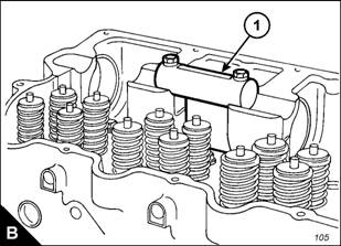
Use the bolts of the rocker shaft to retain the cradle tool (B), GE5008, at the position shown (B).
Continued
![]() 2800
2800
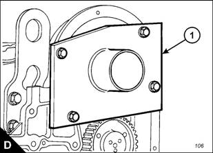
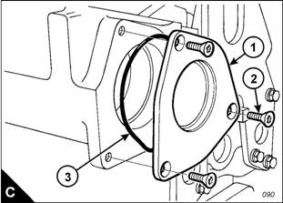
4 Remove the rear cover (C), complete with s eal (C).
5 Fit the camshaft guide (D), GE5007, to the gear case. Do not tighten the bolts for the guide at this stage.
Note: It is necessary to install two pilots, GE5005, on the rear end of the camshaft. The second pilot will
support the rear of the camshaft as it is moved from the cylinder head and into the guide, GE5007.
6 Install a pilot tool, GE5005, into the threaded hole at the rear end of the camshaft. Then attach the second
pilot tool, GE5005, to the first.
7 Withdraw the camshaft until it enters the bore of the camshaft guide. Tighten the bolts which retain the
guide on the gear case.
8 Use the lifting hooks, GE50025, to move the camshaft toward the front of the engine.
Caution: During use of the lifting hooks do not raise the camshaft; the camshaft should be supported by the
cradle, GE5008. If the camshaft is rais ed, damage to the camshaft bearings can occur.
9 Withdraw the camshaft from the cylinder head just enough for a strap and hoist to be attached. Attach a
suitable strap and hoist to support the camshaft, ensure that the camshaft is kept level and withdraw it from
the cylinder head. The camshaft weighs approximately 9 kg (85 lb).


![]()
To fit
2800
Fit the two pilot tools, GE5005, to the rear end of the camshaft. Ensure that the camshaft and camshaft
bearings have been cleaned thoroughly. Apply clean engine oil to the lobes and journals of the camshaft. Apply
a thin coat of clean engine oil to the camshaft bearings.
2 Fit the camshaft guide (E), GE5007, to the gear case cover, but do not tighten the bolts fully.
Insert the alignment sleeve (E2), GE5006, through the camshaft guide (E) and into the camshaft bearings
to align the camshaft guide correctly. Tighten the bolts which retain the camshaft guide, GE5007, on the gear
case. Remove the alignment sleeve; the sleeve should move freely from the bore of the camshaft guide,
GE5007.
4 Fit the cradle tool (F), GE5008, at the position shown (F).
Note: Rotate the camshaft in both directions during installation to prevent binding.
5 Use a suitable strap and hoist to support the camshaft. Insert the camshaft through the guide and into the
cylinder head. Move the camshaft into the head as far as the strap and hoist will allow.
6 Remove the strap and hoist. Rotate the camshaft during installation. Do not allow the end of the camshaft
to drop during removal of the hoist as the bearings can be damaged. Use the lifting hooks, GE50025, to
support the camshaft during installation.
7 Remove the pilot tools and push the camshaft fully into its bore.
8 Inspect the seal (G) and renew if necessary. Fit the rear cover (G), complete with seal (G).
Continued![]() 2800
2800
9 Remove the cradle tool and the camshaft guide.
0 Fit new ‘O’ ring seals to the camshaft front seal plate. Apply a small amount of engine lubricating oil to the
‘O’ ring seal on the outside of the plate. Fit the seal plate with the face seal against the c ylinder head. Insert
the adapter plate and fit the thrust plate. Apply thread lock c ompound, 2820 7, to the three bolts, fit the
bolts and tighten.
Note: Camshaft timing is very important. During installation of the camshaft assembly, ensure that the timing
marks on the camshaft gear and the gear case cover are aligned when number one cylinder is at top centre
(TDC).
Fit the guide stud, GE5009, to the camshaft.
2 Fit the camshaft gear; align the hole in the gear with the dowel pin on the adapter plate. If the timing mark
on gear does not align with the pointer at the top of the gear case, remove the gear and rotate the camshaft
until the gear can be installed with the marks aligned.
Fit the bolts which retain the gear, remov e the guide stud and fit the bolt which remains. Tighten the bolts
to a torque of 240 +/- 40 Nm (77 +/- 0 lbf ft).
4 Fit the camshaft timing sensor to its location behind the top of the gear case and connect the lead.
5 Fit the gear case cover, Operation 6-.
6 Remove the timing bolt from the flywheel and fit the cover and plug.
7 Install the rocker lever and shaft assemblies, Operation -2.

![]()
![]()
2800
How to set the backlash for the camshaft gear
Operation -
If the cylinder head or the camshaft is removed, the backlash between the camshaft gear (A) and the
adjustable idler gear (A2) must be checked and, if necessary, adjusted. The backlash between the camshaft
gear and the adjustable idler gear, and also between the adjustable idler gear (A2) and the main idler gear
(A), must be 0,25 +/- 0,08 mm (0.00 +/- 0.00 in).
Note: This procedure must be performed before the rocker lever and shaft ass emblies are fitted.
Remove the main idler gear (A). Hold the camshaft gear stationary and use a dial tes t indicator (DTI),
mounted on the gear case, to check the backlash of the adjustable idler gear.
2 Fit the main idler gear (A), hold the main idler gear stationary and measure the backlash on the adjustable
idler gear.
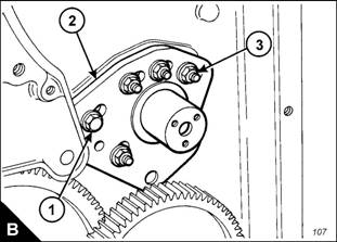
To adjust the backlash, remove the three bolts and thrust plate which retain the adjustable idler gear (A2)
and remove the gear. Loosen the five nuts (B) and the bolt (B) which retain the stub axle (B2) and move the
stub axle by the relevant amount. Tighten the nuts and bolt to a torque of 47 +/- 9 Nm (5 +/- 7 lbf ft).
4 Fit the idler gear. Retain with the thrust plate and three bolts. Check again the backlash between the
adjustable idler gear and the camshaft gear, and also between the adjustable idler gear (A2) and the main idler
gear (A), as given in steps and 2. Repeat the procedure if necessary until the correct backlash settings have
been obtained.
5 When the correct backlash settings have been obtained, remove the adjustable idler gear and proceed as
follows: Remove one of the nuts which retains the idler axle, apply a s mall amount of Loctite 542 to the threads
of the stud, fit the nut and tighten to a torque of 47 +/- 9 Nm (5 +/- 7 lbf ft). Repeat this procedure for the other
four nuts and the bolt; work on one nut or bolt at a time so that the pos ition of the stub axle is not affected.
 fg wilson 滤清器901 102,帕金斯死火电磁阀,400千瓦沃尔沃发电机组配件,perkins发电机p30e1滤清器,成都帕金斯柴油发电机组配件,林德帕金斯柴油泵,山东珀金斯配件 ,美国康明斯发动机配件哪里有,台州康明斯配件专卖店,帕金斯发动机涡轮增压器哪里有,沃尔沃柴油机配件 ,帕金斯1100型涡轮增压器,帕金斯油泵齿,帕金斯发电机ecm板价
400-100-8969 15088860848
0574-26871589 15267810868
0574-26886646 15706865167
0574-26871569 18658287286
