 English
 Espaol
 Franais
 阿拉伯
阿拉伯 中文(简)
中文(简) Deutsch
 Italiano
 Português
 日本
日本 韩国
韩国 български
 hrvatski
 esky
esky Dansk
Dansk Nederlands
 suomi
suomi Ελληνικ
 印度
印度 norsk
norsk Polski
 Roman
Roman русский
 Svenska
Perkins2806柴油发动机齿轮箱盖
Perkins柴油发动机齿轮箱盖
Gear case and drive assembly
General information
The cast iron gear case c ontains the timing gears for the engine and the gears whic h drive the coolant pump
(A4), the lubricating oil pump (A) and the fuel transfer pump (A8). All of the gears are spur gears.
An adjustable idler gear (A6) provides the backlash between the main idler (A7) and the camshaft gear (A5).
If the cylinder head and head gasket are removed, the tolerances may change and the position of the
adjustable idler gear can be adjusted to obtain the correct backlash settings.
The camshaft drive gear (A5) is fitted with pendulum rollers. These are designed to counteract the injector
pulses and eliminate vibration and noise.
For correct engine timing, a line is provided on the large gear (A) of the compound idler which aligns with a
‘V’ on the crankshaft gear (A2), and a mark on the camshaft drive gear aligns with a line at the top of the gear
case.
![]() 6
6
Gear case cover
2800
To remove and to fit
To remove
Remove the radiator, Operation 2.
2 Remove the fan, Operation 2-5.
Operation 6-
Loosen the bolts which retain the gear case cover. Do not remove the bolts from the ass embly, allow them
to be retained by the seal.
4 Remove the gear case cover.
To fit
Note: Ensure that all contact surfaces of the seal and the gear case are clean and free from oil, paint, burrs or
debris.
Examine the seal and renew if necessary, clean the contact surfaces of the seal and the gear case.
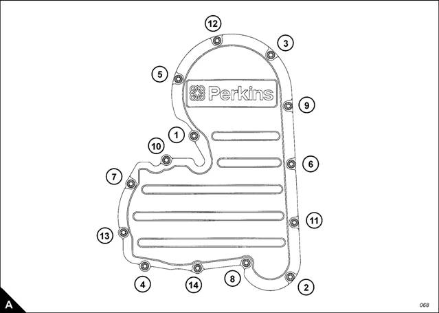
2 Fit the gear case cover and tighten the bolts, in the sequence shown (A), to a torque of 20 Nm (5 lbf ft).
Fit the fan, Operation 2-5.
4 Fit the radiator, Operation 2.
| |||||||||||||||||
Timing gears
To remove and to fit
Special requirements
Operation 6-2
To remove
Thread lock compound (0 ml )
2820 7
|
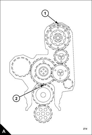
one cylinder as follows:
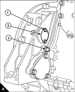
2 Remove the top bolt (A) from the cover (A2) on the flywheel housing and loosen the other cov er bolt to
allow the cover to open. The top bolt (A) is the timing bolt.
Caution: If a customer-fitted speed sensor is fitted to the flywheel housing, it must be removed before the
engine turning tool can be inserted.
Remove the plug (A) from the timing bolt location in the flywheel housing and fit the timing bolt.
4 Insert the engine turning tool, CH48, into the flywheel housing through the aperture behind the cover
(A2). Use a /2 inch drive ratchet with the turning tool to rotate the engine flywheel in the normal direction of
rotation (anti-clockwise when viewed on the flywheel) until the timing bolt engages with the threaded hole in
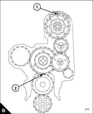
the flywheel. When the number one piston is at top dead centre on its compression stroke, the mark on the
cams haft gear is be aligned with the mark on the gear case (B). If the mark is not aligned, withdraw the timing
bolt, rotate the crankshaft a further 60 degrees in the normal direction of rotation and insert the timing bolt
again.
Caution: If the flywheel is turned past the threaded hole, the flywheel must be turned in the opposite direction
for approximately 45 degrees and then back in the normal direc tion of rotation until the timing bolt engages
with the threaded hole. This is to eliminate backlash.
Continued
![]() 6
6
2800
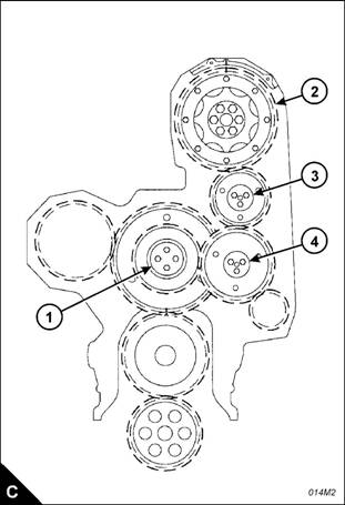
5 Remove the rocker lever and rocker shaft assemblies, Operation -2. If the camshaft gear (C2) is to be
removed, slacken the six retaining bolts before the removal of the rocker lever and rocker shaft assemblies.
6 Remove the camshaft gear (C2), if relev ant. Use the guide stud, GE5009. If the gear case is to be removed,
the c amshaft gear should be removed at this stage.
Caution: Do not rotate the crankshaft with the camshaft gear or any of the idler gears removed and the rocker
shaft assemblies installed. Damage can be caused to the pistons and valves, or to both.
7 Remove the three bolts and the thrust plate (C) and remove the adjustable idler. Discard the bolts.
8 Check the condition of the bearing in the gear. Renew the bearing if it is worn or damaged.
9 Remove the three bolts and the thrust plate (C4) and remove the main idler. Discard the bolts.
0 Check the condition of the bearing in the gear. Renew the bearing if it is worn or damaged.
Remove the four bolts and the thrust plate (C) and withdraw the compound idler. Discard the bolts.
2 Check the condition of the bearing in the gear. Renew the bearing if it is worn or damaged.
Note: If the nuts for the adjustable idler axle are loosened, the backlash for the camshaft gear and main idler
gear will have to be adjusted during the assembly operation. Refer to Operation -.
Check the condition of the shaft for the adjustable idler. If the bearing diameter of the shaft is worn or
damaged, remove the nuts and bolt and renew the assembly. Apply thread lock compound, 2820 7, to the
bolt and five studs , fit the bolt and nuts and tighten to a torque of 50 +/- 0 Nm (7 +/- 7 lbf ft).
4 Check the condition of the shaft for the main idler. If the bearing diameter of the shaft is worn or damaged,
remove the nuts and bolt and renew the assembly. Apply thread lock compound, 2820 7, to the bolt and
five studs, fit the bolt and nuts and tighten to a torque of 50 +/- 0 Nm (7 +/- 7 lbf ft).
5 Check the condition of the s haft for the compound idler. Renew the shaft if the bearing diameter is worn or
damaged. If the shaft is removed, renew the five bolts which retain the shaft. Apply thread lock compound,
2820 7, to the bolts and tighten to a torque of 50 +/- 0 Nm (7 +/- 7 lbf ft).![]() 2800
2800
To fit
Fit the assembly of the compound idler to its shaft, ensure that the "V" timing mark on the crankshaft is
aligned with the marks on the large gear of the compound idler. Fit the thrust plate and fit new bolts. Tighten
the bolts to a torque of 28 +/- 7 Nm (2 +/- 5 lbf ft).
2 Fit the main idler gear to the shaft assembly. Fit the thrust plate and fit new bolts. Apply thread lock
compound, 2820 7, to the bolts and tighten to a torque of 28 +/- 7 Nm (2 +/- 5 lbf ft).
Fit the adjustable idler gear to the shaft assembly. Fit the thrust plate and fit new bolts. Apply thread lock
compound, 2820 7, to the bolts and tighten to a torque of 28 +/- 7 Nm (2 +/- 5 lbf ft).
4 Fit the camshaft gear, if it was removed: align the hole in the gear with the dowel pin on the adapter plate.
If the timing mark on the gear does not align with the pointer at the top of the gear case, remove the gear and
rotate the camshaft until the gear can be installed with the marks aligned. Ensure that the timing marks on the
crankshaft gear and compound idler are aligned.
5 Fit the bolts which retain the gear, remove the guide stud and fit the bolt which remains. Tighten the bolts to
a torque of 240 +/- 40 Nm (77 +/- 0 lbf ft).
6 Fit the gear case cov er, Operation 6-.
7 Remove the timing bolt from the flywheel and fit the cover and plug.
8 Install the rocker lever and shaft assemblies, Operation -2.
![]()
![]() 6
6
2800
How to check the position of the timing gears
Operation 6-
Fuel injection timing and the operation of the rocker valves depends on the correct alignment of the timing
gears. When the timing mark on the camshaft gear (A) is aligned with the mark on the gear case, the ‘V’ on
the c rankshaft must also be aligned exactly with the line (A2) on the idler gear. At this pos ition the piston of
cylinder number is at top dead centre (TDC). This can be confirmed by the insertion of the timing bolt into
the flywheel as described in Timing gears - To remove and to fit, Operation 6-2.
珀金斯perkins皮带,帕金斯804d启动马达 三菱发动机四配套,康明斯QST30喷油泵,康明斯发动机控制器ecm,沃尔沃发动机控制器ecm,PERKINS发动机控制器ecm,Volvo 7d at节温器,铂金斯发动机404d 22配件
400-100-8969 15088860848
0574-26871589 15267810868
0574-26886646 15706865167
0574-26871569 18658287286
