 English
 Espaol
 Franais
 阿拉伯
阿拉伯 中文(简)
中文(简) Deutsch
 Italiano
 Português
 日本
日本 韩国
韩国 български
 hrvatski
 esky
esky Dansk
Dansk Nederlands
 suomi
suomi Ελληνικ
 印度
印度 norsk
norsk Polski
 Roman
Roman русский
 Svenska
英国帕金斯电喷柴油发动机维修服务工具软件
英国帕金斯电喷柴油发动机维修服务工具软件
Service tools and diagnostics
2800 Series
The Perkins TIPSS-EST service tool is designed to help the service technician analyse and locate faults or
problems within the system. They are required to perform calibrations and to read or change engine
parameters.
Perkins TIPSS-EST is a software program that runs on a personal computer and requires a communication
adapter to translate information from the Perkins Data Link to the computer RS232 port.
Perkins TIPSS-EST can be used to display the following information:
Programmable parameter settings
Active and logged diagnostic codes
Logged events
Engine rating history
Histograms
Custom data
ECM date/time clock
Perkins TIPSS-EST can also be used to perform the following functions:
Diagnostic tests
Sensor calibrations
Flas h programming
Parameter programming
Copy configuration (ECM replacement)
Data logging
Real time graphing
There are several adapter cables, breakout T cables, etc that are used in order to access measurements of
signals. A heavy duty multimeter is suitable in order to make the necessary measurements. A multimeter that
has the ability to measure duty cycle may also be required. Other special tools include those needed to
measure pressure and temperature. For further details refer to Chapter 5, Special tools.
A diagnostic code reader is also available. This is a hand held unit which allows reading certain parameters
and diagnostic codes.
Diagnostic Manual, TSD 3453E, Issue 3
|
Programming parameters
Connecting the TIPSS-EST
The communications adapter is powered by 24 Volts DC from the engine battery. This permits operation
beside the engine to allow use during engine operation.
Use the following procedures to connect the service tool to the engine.
1 Stop the engine by turning the key switch to the OFF position.
2 Connect the service tool harness cable on the engine to the communication adapter. Refer "Connecting
TIPSS-EST using a TIPSS communication adapter" on page 22.
3 Connect the communication adapter to the PC using the appropriate cable.
4 Turn the key switch to the ON position in order to begin testing. The service tool will operate while the engine
is running or with the engine OFF and the key switch ON. If the tool does not communicate with the ECM
disconnect and reconnect the diagnostics connector cable. Check the communication. If the problem is still
present refer to Test 45: Perkins Data Link circuit test on page 118.
Notes:
The service tool may restart during engine cranking due to a voltage dip on the battery line.
The TIPSS-EST must be configured to communicate with the specific type of communication adapter used.
Go to the "Preferences" menu that is located under "Utilities" in order to select the appropriate
communication adapter.
Diagnostic Manual, TSD 3453E, Issue 3
![]() 3
3
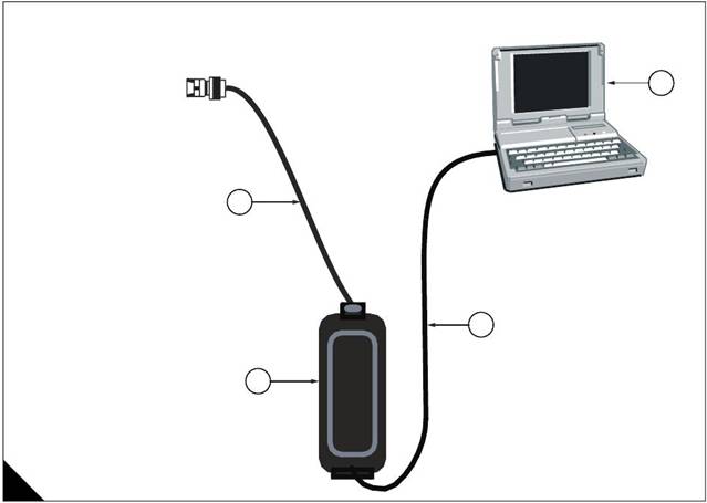
Connecting TIPSS-EST using a TIPSS communication adapter
1 PC with TIPSS-EST installed
2 PC to communication adapter cable (27610169)
3 Communication adapter (27610165)
4 Service tool harness cable (27610168)
2800 Series
Diagnostic Manual, TSD 3453E, Issue 3![]() 2800 Series
2800 Series
Passwords
Factory passwords
Factory passwords are required to perform each of the following functions:
1 Program a new ECM
When an ECM is replaced the system configuration parameters must be programmed into the new ECM. A
new ECM will allow these parameters to be programmed once without factory passwords. After the initial
programming these parameters are protec ted by factory passwords.
2 Rerate to another engine family
This requires changing the ECM software code, which is protected by factory passwords.
3 Read customer passwords
If the owner loses his customer passwords, he will not be able to program customer parameters. By using
factory passwords, one can read c ustomer passwords, then use those customer passwords to program
customer parameters.
4 Clear certain diagnostic codes
Diagnostic code 253-02 Incorrect ECM software requires a factory password to clear the code. This diagnostic
code should be cleared only if you are certain that the ECM software is for the specific engine.
Caution: Operating the engine with ECM software not designed for that engine will result in engine damage.
Be sure the ECM software is correct for your engine.
5 Certain other codes require customer passwords. The majority of logged codes do not require passwords
to be cleared. To obtain factory passwords, proceed as if you already hav e the password. At some point, if the
factory passwords are actually needed, TIPSS-EST will request the factory passwords and display the
information required to obtain the passwords.
Customer passwords
If customer passwords have been entered, they are then required to change ANY customer parameter.
TIPSS-EST can be used to change customer parameters. To obtain customer passwords, contact the supplier
of the equipment. If the owner has lost the passwords, customer passwords may be read by using TIPSS-EST
(factory passwords are required in order to read customer passwords) by using the following procedure.
1 In TIPSS-EST access "Passwords" under the "Information" menu.
2 When the "Factory Password" screen appears, record the information listed.
3 Obtain the factory passwords. The information recorded above must be provided, and generates a
permanent record at Perkins of the access.
4 From the "Factory Password" screen, enter the factory passwords.
5 When the "View Customer Passwords" screen appears, record the customer passwords. The customer
passwords may then be used to change customer parameters.
Diagnostic Manual, TSD 3453E, Issue 3![]() 3
3
Programming a new ECM
2800 Series
The Engine Control Module or ECM is the brain of the system. When a problem occurs, it is easy to assume
that the ECM is responsible. This is usually the wrong conclus ion.
Most failures occur at the wiring and connectors or at a sensor input/output. Follow the diagnostic test
procedures and do not replace an ECM on speculation.
However, when your diagnosis indicates that a failure has in fact occurred in the ECM, the following procedure
outlines the steps required to replace a faulty ECM.
Note: If an ECM replacement is required, the ECM parameters and injector trim codes can be transferred from
the suspect ECM to the replacement ECM. This feature requires TIPSS-EST and is only possible if the suspect
ECM can communicate with the TIPSS-EST.
Replacing the ECM using TIPSS-EST ECM replacement feature
Note: The Test ECM referred to below is another identical ECM to that fitted to the engine. There is no special
Test ECM available.
1 Ensure that the ECM is the problem by first temporarily connecting a test ECM. Hang the test ECM on the
side of the engine. Flash program the identical software that was used in the suspect ECM into the test ECM.
Use the TIPSS-EST ECM replacement feature to copy the parameter configuration of the suspect ECM into
the test ECM. Ensure that the parameters in the test ECM are programmed the same as the parameters in the
suspect one.
2 If the test ECM repairs the problem, reconnect the suspect ECM. Check that the problem returns when the
suspect ECM is reconnected.
3 Select the ECM Replacement feature under the "Service/Copy Configuration" menu and load the
parameters from the failed ECM.
4 Temporarily connect the new ECM by connecting both ECM connectors. Do not mount the ECM on the
engine yet.
5 Flash program the ECM software into the new ECM if the software is not already installed.
Note: The new ECM may be shipped with no software installed or may have been pre-flashed at the factory.
Following reflashing the engine may be inoperable until a factory password has been obtained.
6 Use the TIPSS-EST ECM replacement feature to program the new ECM
7 Enter rating number parameter into the new ECM
8 Check for active codes. Program any required parameters that have not been programmed.
Note: On initial power-up of a new ECM, the Rating Number parameter must be programmed to avoid a
268-02 Check Programmable Parameters diagnostic code.
Install the new ECM on the engine and after checking for correct operation perform a timing calibration.
Diagnostic Manual, TSD 3453E, Issue 3![]() 2800 Series
2800 Series
Replacing the ECM (if ECM replacement feature cannot be used)
1 Ensure that the ECM is the problem by first temporarily connecting a test ECM. Hang the test ECM on the
side of the engine. Flash program the identical software that was used in the suspect ECM into the test ECM.
Program any parameters that are necessary to use the ECM for the test. Program the parameters exactly the
same as they are in the suspect ECM.
2 If the test ECM repairs the problem, reconnect the suspect ECM. Check that the problem returns when the
suspect ECM is reconnected.
3 Obtain customer parameters from the failed ECM
Obtain and record the customer passwords. If the customer has lost or forgotten their passwords, obtain
factory passwords to get them.
Use TIPSS-EST to access customer specified parameters from the ECM that is being replaced. If the ECM
does not communicate with the electronic service tool, obtain the required parameter list from the OEM.
Record the customer parameters.
4 Record ECM current totals.
5 Temporarily connect the new ECM by connecting both ECM connectors. Do not mount the ECM to the
engine until the timing calibration has been performed.
6 Flash program the software into the new ECM if the software is not already installed.
Note: The new ECM may be shipped with no software installed, or may have been pre-flashed at the factory.
7 Obtain factory passwords if required. The following parameters can be programmed once on a new ECM
without factory passwords:
Full Load Setting (FLS)
Full Torque Setting (FTS)
Engine serial number
System configuration parameters must be entered before the customer spec ified parameters are entered.
If customer parameters are entered before the system configuration parameters, the total tattletale will change.
It will then be necessary to obtain another set of factory passwords in order to access system configuration
parameters.
8 Record the following information from the engine information plate:
Engine serial number
Obtain the following information from the factory:
Full Load Setting (FLS)
Full Torque Setting (FTS)
Injec tor Trim Codes
Use TIPSS-EST to access system configuration parameters. When the "Factory Specified Passwords" screen
appears record the following information:
ECM serial number
Engine serial number
TIPSS-EST serial number
Total tattletale
Reason code
Leave TIPSS-EST on the "Factory Specified Passwords" screen and obtain the factory passwords.
Continued
Diagnostic Manual, TSD 3453E, Issue 3![]() 3
3
9 Program the new ECM
2800 Series
On initial powerup of a new ECM the following three parameters must be programmed to avoid a 268-02
Check Programmable Parameters diagnostic code:
Full Load Setting (FLS)
Full Torque Setting (FTS)
Engine serial number
Use TIPSS-EST to access system configuration parameters. Enter the recorded values for the following
parameters:
Full Load Setting (FLS)
Full Torque Setting (FTS)
Engine serial number
Injector trim codes
Use TIPSS-EST to access customer specified parameters. Enter the customer spec ified parameters and the
original customer passwords.
Use TIPSS-EST to access current totals from the "Read/Change Current Totals" main menu. Using the
recorded factory passwords enter the totals from the original ECM.
Use the "Service\Calibrations\Timing Calibration" menu to calibrate the timing. Refer to Test 46: Engine
speed/timing circuit test on page 126.
10 Install the new ECM on the engine.
Diagnostic Manual, TSD 3453E, Issue 3![]() 2800 Series
2800 Series
Programming an ECM using flash programming
1 Connect the PC to the appropriate communication adapter and connect the communication adapter to the
ECM. Refer to "Connecting TIPSS-EST using a TIPSS communication adapter" on page 22.
2 Start the WinFlash PC Program.
3 Ensure that the key switch is ON and the engine is OFF.
4 Select the part number of the engine software that needs to be programmed into the ECM and proceed with
programming. A new ECM is shipped with no software loaded.
Note: The WinFlash PC program provides the ECM, application and software part number of the selected file.
Ensure that this file matches the engine before you begin to Flash the file into the ECM
PC program software messages and their meaning
A new ECM comes unprogrammed. An unprogrammed ECM will prompt you for all three of the following
messages. The information that is contained in the ECM Status will be scrambled and meaningless if the
module has not been programmed previously (this is normal).
Message: The engine ID in the flash file does not match the engine ID in the ECM
Meaning: The ECM has software for a different engine.
Solution: Stop the transfer and access information about the ECM Status under the "Electronic Control
Module" menu. Ensure that the file you are about to transfer matches the engine application.
Message: The application ID in the flash file does not match the application ID in the ECM
Meaning: The ECM has software for a different application.
Solution: Stop the transfer and access information about the ECM Status under the "Electronic Control
Module" menu. Ensure that the file you are about to transfer is for the correct engine type.
Message: The ID of the ECM in the flash file does not match the ID of the ECM in the ECM
Meaning: The ECM is not for use with this application.
Solution: Stop the transfer and access information about the ECM status under the "Electronic Control
Module" menu. Ensure that the ECM on the engine is for the correct application.
Note: If you access the ECM status under the "Engine Control Module" menu, but do not program the ECM,
complete the following procedure.
Turn the key switch to the OFF position, and then to the ON position before using TIPSS-EST. If the key switch
is not cycled after reading the ECM Status , the ECM will not communicate with your service tool or will not start.
Cycling the key switch is not necessary after the software has been successfully programmed using the
WinFlash program.
5 Start the engine and check for correct operation.
Program any parameters not previously in the old software if a 268-02 Check Programmable Parameters
diagnostic code is active. Read the diagnostic code from service tool "Active Diagnostic Code" screen in order
to determine the parameter(s) requiring programming.
On initial powerup of a new ECM three parameters must be programmed to avoid a 268-02 Check
Programmable Parameters diagnostic code:
Full Load Setting (FLS)
Full Torque Setting (FTS)
Engine serial number
Refer to "Programming a new ECM" on page 24.
Diagnostic Manual, TSD 3453E, Issue 3![]() 3
3
ECM date/time clock
ECM date/time stamped information
2800 Series
The ECM date and time can be programmed with the TIPSS-EST service tool (factory passwords are required
to change these parameters). This will display the programmed date in month/day/year format and the
programmed time in hour:minute:second format. The tool has the option to program any date/time or
automatically select the date/time stored in the PC real time clock.
The date and time will remain programmed in the ECM even if the unswitched battery connections are
removed.
The ECM Date/time clock is used to stamp the following critical event codes:
360-3 Low oil pressure Shutdown
361-3 High coolant temperature Shutdown
Before adjusting the ECM date/time clock
Before adjusting the ECM date/time clock, ask the owner/operator if the time stamped information should be
recorded. After the time stamped information is recorded, clear this information before adjusting the ECM date/
time clock. This is a very important step if the adjustment of the clock is a big adjustment. This will prevent
unnecessary confusion if someone else views the information at a later date.
Determining time stamped information occurrence
When viewing time stamped information remember that someone may have incorrectly or never set the clock.
Use the time currently set in the ECM to compare any ECM recorded information to the time the ECM indicates
to determine how long ago the time stamped event occurred.
Caution: Do not replace an ECM because of an incorrect time.
The following example indicates the correct use of the clock.
Example use of ECM date/time stamped information
The TIPSS-EST service tool indicates a Low Oil Pressure occurred on NOV 19 1998 10:30:46 and that the
current time of day in the ECM is NOV 24 1998 11:20:58.
This indicates that the problem occurred approximately 5 days and 50 minutes ago.
Caution: Do not compare it to the current time at your location.
If the ECM time is significantly different than your current time, for example the wrong month is programmed,
ensure y ou have recorded the time stamped information if it is important. After recording the information, clear
the code and then adjust the clock.Diagnostic Manual, TSD 3453E, Issue 3
ECM diagnostic clock
The diagnostic clock should not be confused with the ECM date/time clock. The diagnostic clock records the
actual hours the ECM has been powered (key switch ON and engine running). This information is maintained
even if the unswitched battery connections are removed. The clock information is used to log diagnostic code
and event code occurrences. Logged diagnostic codes and event c odes display the diagnostic clock hour of
the first and last occurrence and the total number of occurrences.
Note: Actual engine running hours (total time) can be obtained from the "Current Totals" menu of TIPSS-EST.
Injector codes
Injector codes are etched on each injector. The injector codes can be viewed/changed using TIPSS-EST by
selecting the "Calibrations" screen under the "Service" menu. The injector codes calibration is located under
the "Calibration" menu. The injector code must match the code on the corresponding injector. When an injector
is replaced, reprogram the new code for the new injector.
TIPSS-EST cylinder cut-out test
The 2300 and 2800 Series engines use electronic fuel injectors. These injectors are mechanically actuated
and electronically energized. The cylinder cut-out tests are used to confirm that the cylinders are functioning
correctly.
The cylinder cut-out test allows a specific cylinder to be cut out while the fuel position is monitored for the
remaining cylinders.
To perform a cylinder cut-out test, connect TIPSS-EST to the diagnostic connector as described in
"Connecting the TIPSS-EST" on page 21, and select the Cylinder cut-out test located under the "Diagnostics"
menu.
The Cylinder cut-out test opens with the manual test. At the bottom of the TIPSS-EST screen there is a row of
buttons that function as follows:
Change toggles the highlighted cylinder between powered and not powered
Power All returns all cylinders to the normal operating state
Start initiates the automated Cylinder cut-out test.
Stop terminates the automated test.
Results displays the test results.
Print allows the contents of the screen to be previewed or to be sent to a file or printer.
Programming parameters
Many programmable parameters affect engine operation. These parameters may be changed by using the
TIPSS-EST service tool. The parameters are stored in the ECM. Whilst any parameter can be read, passwords
can be used to protect parameters from unauthorized changes.
Two categories contain these various parameters:
System configuration parameters
System configuration parameters can only be altered with factory passwords by using TIPSS-EST.
Customer specified parameters
Customer specified parameters can be changed by using the TIPSS-EST service tool (this may require
customer passwords if customer passwords have been programmed). Refer to "Passwords" on page 13 for
more details on how to receive and use factory and customer passwords.
Diagnostic Manual, TSD 3453E, Issue 3![]() 3
3
System configuration parameters
2800 Series
System configuration parameters affect critical settings for the engine. They are programmed at the factory
and would normally never need to be changed through the life of the engine. A complete list of these
parameters is given in the table on the following page.
Note: System Configuration Parameters must be reprogrammed if an ECM is replaced. Failure to programme
these parameters will result in a 268-02 Check Programmable Parameters diagnostic code.
Proper values for these parameters are stamped on the engine information ratings plate located on the valve
cover or air inlet manifold. Factory passwords are required to change these parameters. The following
information is a description of the system configuration parameters.
Full Load Setting (FLS)
Number representing fuel system adjustment made at the factory to “fine tune” the fuel system. The correct
value for this parameter is stamped on the engine information ratings plate. A new ECM requires this
parameter to be programmed to avoid generating a 268-02 Check Programmable Parameters diagnostic code.
Full Torque Setting (FTS)
Similar to Full Load Setting. This parameter must be programmed to avoid generating a 268-02 Check
Programmable Parameters diagnostic code.
Software part number
This is the part number of the software flashed into the ECM.
Engine serial number
This should be programmed to match the engine serial number that is stamped on the engine information plate.
A new ECM is delivered without the engine serial number programmed.
ECM serial number
This is a read-only parameter which dis plays the serial number of the ECM.
Software release date
This parameter is defined by the ECM software and is not programmable. It is used to provide the version of
the software. Customer parameters software changes can be tracked by this date. The date is provided in the
month and year (NOV99), where NOV is the month (November) and 99 is the year (1999).
Critical override switch installed
The critical override switch, if fitted and enabled, allows the engine to continue running even if engine oil
pressure or coolant temperature have reached the limits where the engine would normally be shutdown. If the
engine is run in this condition, the engine warranty is void and any events occurring are stored in the ECM with
time and date stamping. Implementation of this facility requires a factory password.
Total tattletale
Displays the total number of times the configuration parameters have been changed.
Diagnostic Manual, TSD 3453E, Issue 3

![]() 2800 Series
2800 Series
Configuration parameters
Configuration Parameter Description
Selected Engine Rating
Rating Number
Rated Frequency
Rated Genset Speed
Rated Real Genset Power
Rated Apparent Genset Power
Engine Rating Application Type
External Speed Selection Switch Installed
ECM Identification Parameters
Equipment ID
Engine Serial Number
ECM Serial Number
ECM Software Part Number
ECM Software Release Date
ECM Software Description
Security Access Parameters
Total Tattletale
Engine/Gear Parameters
Engine Acceleration. Rate
Droop/Isochronous Switch Installed
Droop/Isochronous Selection
Engine Speed Droop
Critical Override Switch Installed
Digital Speed Control Installed
Speed Control Min Speed
Speed Control Max Speed
Digital Speed Control Ramp Rate
Crank Terminate Speed
I/O Configuration Parameters
Desired speed Arrangement
System Parameters
FLS
FTS
Governor ProportionalGain
Governor Minimum Stability Factor
Governor Maximum Stability Factor
Passwords
Customer Password 1
Customer Password 2
R/W Security
Customer
Read Only
Read Only
Read Only
Read Only
Read Only
Customer
Customer
Factory
Read Only
Read Only
Read Only
Read Only
Read Only
Customer
Customer
Customer
Customer
Factory
Customer
Customer
Customer
Customer
Customer
Customer
Factory
Factory
None
None
None
Customer
Customer
Diagnostic Manual, TSD 3453E, Issue 3![]() 3
3
Customer specified parameters
2800 Series
Customer specified parameters allow the OEM to modify engine parameters to suit the application.
Customer parameters may be changed repeatedly as a customer changes his requirements. Customer
passwords are required to change these parameters.
The following information is a brief description of the customer specified parameters.
Rating duty selection
This enables selection of the engine rating from a series of maps within the ECM. Changing the rating requires
a customer password. The available ratings within the ECM will vary with engine type and specification.
Rated frequency
This displays the rated frequency of the set, i.e. 50 Hz or 60 Hz, determined by the rating selection and the
status of the external speed selection switch. This parameter is read only.
Rated speed
This displays the rated speed of the engine, i.e. 1500 rev/min or 1800 rev/min, determined by the rating
selection and the status of the external speed selection switch. This parameter is read only.
Rated real genset power
This displays the maximum power in kW of the currently selected rating. This parameter is read only.
Rated apparent genset power
This displays the maximum power in kVA of the currently selected rating. This parameter is read only.
Rating configuration
This displays the configuration of the currently selected rating. The possible configurations are:
Standby power
Limited time prime power
Prime power
Continuous or baseload power
For definitions of these ratings, refer to ISO8528. This parameter is read only.
Note: Not all of the abov e rating configurations will be available in a given ECM software file.
External speed selection switch enable
For dual speed (1500 rev/min or 1800 rev/min) applications, where an external speed selection switch is
required, this parameter enables the functionality of the speed selection switch within the software. Changing
this parameter requires a customer password.
Engine startup acceleration rate
Enables the acceleration rate of the engine in rev/min/s, from idle speed to rated speed, to be programmed.
Control of this parameter enables any overshoot in speed on start up to be limited. Changing this parameter
requires a customer password.
Droop/isochronous switch enable
Determines whether the external droop/isochronous switch is enabled or disabled. Changing this parameter
requires a customer password.
Droop/isochronous selection
The engine will normally be run in isochronous mode i.e. the engine speed is the same at all loads. For certain
applications where parallel operation with another generating set or with the grid is required, it is necessary for
stability reasons to run in droop condition where engine speed drops with load. This parameter enables droop/
isochronous running selection. Changing this parameter requires a customer password.
Note: If an ex ternal droop/isochronous switch is enabled, the position of this switch will over-ride the Droop/
Isochronous selection.Diagnostic Manual, TSD 3453E, Issue 3
![]() 2800 Series
2800 Series
Engine speed droop
If droop operation is selected, this parameter allows the setting of percentage droop i.e. the percentage that
the engine speed will drop with load. This parameter has no effect when the engine is running in isochronous
mode. Changing this parameter requires a customer password.
Digital speed control installed
This parameter determines whether raise/lower switch input control of engine speed is installed. If digital speed
control is not installed, speed control reverts to the analogue or PWM inputs depending on which input is
selected via the desired speed input configuration detailed on the following page. Changing this parameter
requires a customer password.
Digital speed control min speed
This setting determines the minimum speed range of both the raise/lower button control and the analogue
control, for example: if this is set to 100 rev/min and the nominal engine speed is selected for 1500 rev/min,
the minimum speed setting is 1400 rev/min. It does not affect the PWM speed control range which has fixed
min/max limits. Changing this parameter requires a customer password.
Digital speed control max speed
This setting determines the maximum speed range of both the raise/lower button control and the analogue
control, i.e. if this is set to 100 rev/min and the nominal engine speed is selected for 1500 rev/min, the
maximum speed setting is 1600 rev/min. It does not affect the PWM speed control range which has fixed min/
max limits. Changing this parameter requires a customer password.
Digital speed control ramp rate
This setting determines the rate of change of engine speed in rev/min/s when the raise/lower switch inputs are
closed. Changing this parameter requires a customer password.
Crank terminate speed
This parameter is used to set the engine speed at whic h the crank terminate relay output will be switched.
Changing this parameter requires a customer password.
Desired speed input arrangement
This parameter allows selection of the analogue or PWM external speed control if the digital speed control is
not installed. The Analogue or PWM speed control inputs are normally used with generating set load sharing
and synchronising controllers. Changing this parameter requires a customer password.
Note: If PWM or Analogue speed control is selected but there are no inputs to the selected speed control
terminals, the engine will default to running at 1100 rev/min.
If it is not intended to use PWM or analogue speed control then the Digital speed control should be selected.
Governor gain parameters
The adjustable Governor Gain parameters are:
Governor Gain Factor
Governor Minimum Stability Factor
Governor Maximum Stability
Notes:
No engineering units associated with these numbers.
The programmable range is wide for flexibility. The values are valid from 1- 40000. This wide programmable
range may not be fully used on any system. Do not expect to use the whole range.
Diagnostic Manual, TSD 3453E, Issue 3![]() 3
3
Gain explanations
Governor gain factor
2800 Series
The governor gain factor is multiplied to the difference between desired speed and actual speed.
If the governor gain factor value is too large, the engine speed can overshoot the desired speed. The
overshoot is caused by an overcorrection or a steady state instability.
If the governor gain factor is too small, the response necessary to accelerate the engine to the desired
speed must be obtained by ramping the stability terms to a higher value. This process is time consuming
so, as a result, the engine speed is slow to respond.
Governor minimum/maximum stability factor
The stability factor terms work to eliminate a steady state speed error. There are two gain terms used for
stability. If the error is greater than 20 rev/min and the error is increasing, then the maximum stability gain is
functioning. If the error is less than 20 rev/min, then the minimum stability gain is used. This function allows
the use of a high gain that would otherwise cause the engine to be unstable when the engine is operating near
the desired speed.
If either the minimum stability gain or the maximum stability gain is set too high, the governor will provide
more fuel than is necessary to bring the error to zero. The additional fuel will cause the engine speed to
overshoot and ring.
If either the minimum stability gain or the maximum stability gain is set too low, the engine will take too long
to arrive at a steady state speed.
Tuning procedure
1 Turn the key switch to the OFF/RESET position. Connect the TIPSS-EST service tool and chec k that engine
overspeed protection is enabled before beginning the tuning process. Engine overspeed is configured on the
"Service\Monitoring System" screen on TIPSS-EST.
Warning! Performing engine governor tuning without engine overspeed protection could result in serious
engine damage. Ensure that this parameter is ON while performing this procedure.
2 Start the engine. Observe, on the engine mounted genset control panel, that the engine has reached rated
speed. This panel will serve as the speed reference point during this procedure.
3 Enter the "Configuration Parameters" screen on TIPSS-EST.
4 Determine the desired scenario to tune the engine. For example, is the engine having poor response during
specific load assignments or specific load dumps ?
5 Perform the desired load change from step 4. Observe the response of the engine by viewing the engine
speed on the genset mounted control panel, by looking at the system bus frequency response to the load
change, or by listening to the response of the engine.
6 Use the suggestions listed above to determine which gains should be adjusted.
Note: Usually, the governor gain factor should be somewhat lower that the governor minimum stability factor
for optimum performance. The maximum stability factor is typically a smaller value than the minimum stability
gain and governor gain factor.
7 Repeat steps 5,6, and 7 until a desired engine response can be met. Use large adjustments (10% of original
gain) at first to generally tune the engine in the proper manner. As the response is closer to desired, increase
the gains in s maller increments (1% of total gain).
Customer password 1, customer password 2
These are the customer password programmable parameters that can be used to protect certain configuration
parameters from unauthorised changes. ,帕金斯18 9千瓦发动机配件,韩国大宇发电机配件,强鹿kj250发电机配件,帕金斯空滤901 048,perkins 滤清器查询,斗山大宇发电机配件,帕金斯804D 33T发动机高压油泵,perkins发动机 403配件,帕金斯发动机1306 e87tag6配件,帕京斯柴油发电机配件,帕金斯1104a 44 曲轴,南京沃尔沃发电机配件,帕金斯曲轴前油封
400-100-8969 15088860848
0574-26871589 15267810868
0574-26886646 15706865167
0574-26871569 18658287286
