 English
 Espaol
 Franais
 阿拉伯
阿拉伯 中文(简)
中文(简) Deutsch
 Italiano
 Português
 日本
日本 韩国
韩国 български
 hrvatski
 esky
esky Dansk
Dansk Nederlands
 suomi
suomi Ελληνικ
 印度
印度 norsk
norsk Polski
 Roman
Roman русский
 Svenska
帕金斯3008发动机气门座圈的维修拆卸安装与测量方法
5 Apply clean engine lubricating oil to the rollers, to
the face at the end of the tool and to the counterbore
in the cylinder head.
6 Insert the rolling tool in the valve guide and turn
slowly the rolling tool. Apply enough pressure to
spread the material of the cylinder head over the
chamfer of the valve seat insert. Ensure that the face
at the end of the tool is suitably lubricated before the
face at the end of the tool is in contact with the top
face of the insert (A). When this occurs, the cylinder
head is fully rolled over the insert, and the tool can be
removed.
7 Use the valve seat cutter, 21825 842, and the
relevant pilot, to machine to the correct angle, the
seats which have been renewed. Ensure that the
cutter is correct for the angle of the valve seat, which
is giv en on page 59. Lap the valves to the seats.
Clean thoroughly the area around the valves and the
seats and use engineer's blue to check that the faces
of the valves are in full contact across and around the
faces of the valve seats.
8 Fit the valves in their relevant seats and use a
straight edge and a feeler gauge to chec k that the
clearances between the heads of the valves and the
flame face are within the limits given on page 59. If a
clearance is excessive, a new valve must be fitted.
The number of the cylinder and the position of the
valve should be etched above the collet groove on the
A
227
valve stem. Valves must not be stamped or marked
with a centre punch, because cracks may occur.
帕金斯3008发动机气门座圈的维修拆卸安装与测量方法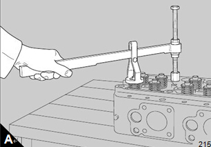
To dismantle and to assemble
Special tools:
Drive handle, 21825 861
Replacer kit for cup plugs, 21825 866
Valve spring compress or, 21825 739
Adaptor, 21825 740
Stirrup, 21825 741
|
Check all cup plugs for signs of coolant leakage.
Plugs that are in doubt can be renewed by use of the
replacer kit, 21825 866, and the drive handle, 21825
861. Apply 'Loctite 575' to new cup plugs before they
are fitted to the cylinder head. If the /8 BSP plug has
been removed because of leakage, clean the plug,
apply 'Loctite 270' to its threads, fit the plug and
tighten it to a torque of 28 Nm (21 lbf ft).
Put the cylinder head, flame face downward, on a
bench with a soft surfac e and remove the valves by
use of the valve spring compressor, 21825 739, with
adaptors 21825 740 and 21825 741. Use the
procedure which follows:
1 Fit the adaptor, 21825 740, into a suitable bolt hole
for the rocker box.

To assemble
|
|
|
|
its correct guide, according to the marking which is
etched on the stem. Lower carefully the assembly of
the cylinder head on to the bench with the flame face
downward, then fit the lower spring seat, spring and
spring retainer or valve rotator, as relevant, over the
valve stem.
Compress each spring assembly and fit the collets
into the collet grooves in the valve stems. Release,
carefully, the valve spring compressor, check that the
collets remain in their correct location, and then
proceed to the next unit.
the cylinder head 12-10
Clean all of the components; use a cleaning fluid
which can be diluted with water and refer to Section
10 on page 15 for relevant information. To remove
heavy carbon deposits from most components: soak
them in solutions of 'Maxan' or 'Ardrox 667'.
Caution: Do not use the 'Maxan' or 'Ardrox'
processes on the valve springs or the surface finish
will be damaged.
If cup plugs were removed, before the cylinder head
was cleaned, they must be renewed before the
cylinder head is given a test under pressure. Apply
'Loctite 575' to the new cup plugs and insert them into
their correct locations in the cylinder head. Use the
relevant kit of removal/replacer tools for the cup
plugs.
Make, locally, enough seals to close all of the
openings for coolant and fit them to the cylinder head.
Connect a pipe from a supply of air to the coolant
galleries. Apply air at a pressure of 207 kN/m (30 lbf/
in ).
Caution: Do NOT exceed 207 kN/m (30 lbf/in ) as
damage may be caused
Put the cylinder head in a tank of water which is at a
temperature of 60°C (140°F) and inspect for bubbles
from around all the cup plugs and injector sleeves.
Renew plugs or sleeves which are not fully sealed.
Remove the seals from the openings for coolant.
Inspect the flame face for signs of damage. If
necessary, the face may be reconditioned by surface
grinding, in four stages, to a maximum of 0,51 mm
(0.020 in). Information about work done must be
etched on an area of the flame face which is not under
the gasket of the cylinder head.
Caution: When a cylinder head flame face has been
machined, the valve seats must be re-cut to maintain
the correct distance between the valve faces and the
flame face of the cylinder head. See fits and
clearances on page 59.
To correct a valve seat
Special tools:
Valve seat tool, 21825 841
Valve seat cutter, 21825 842

It is recommended that all the valve guides are
inspected, and renewed as necessary, before the
work is begun on the valve seat inserts. Ensure that
the bores of the guides are within the limits given at
the end of this sec tion.
1 Inspect the inserts for erosion and cracks. If it is
necessary to correct the ins erts, lightly lap the faces
of the v alve seats and their relevant valves. To correct
the faces of more badly damaged valve seats, use the
valve seat tool, 21825 841, and the cutter, 21825 842,
together with the relevant pilot. To use the tool, fit the
guide (A) and proceed as shown (B). Ensure that the
cutter is correct for the angle of the valve seat, which
is given on on page 59. The surface finish of the valve
seat will be improv ed if a compressed air supply is
used to remove debris during this operation.
Warning! Ensure that eye protection is used during
the above operation.
Caution: During the correction of a valve seat it is
important to remove only the minimum amount of
material.
2 After the inspection and correction of a valve seat
and the relevant v alve, fit the valve into the guide and
chec k the depth of the head of the valve below the
flame face. If the depth is more than the limits given
on page 59 use a new valve to check again. If the
depth is then within acceptable limits, the new valve
must be fitted to the valve seat when the cylinder
head is assembled.
3 To ensure that the valve is fitted in its correct
position, the number of the cylinder and the position
of the valve must be etched above the collet groove
on the valve stem. Valves must not be stamped or
A
B
222
223
marked with a centre punch, because cracks may
occur.
If the depth still exceeds the acceptable limits, a new
valve seat insert must be fitted.
拆卸气门座
Caution:
Before a valve seat insert for an exhaust
valve can be removed, the edge of the casting of the
cylinder head, which is rolled over the insert, must be
cut away (A). A special cutter, 21825 893, and holder,
21825 892, are available for this purpose.
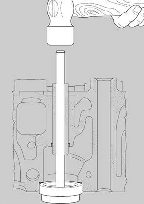
1 If the relevant valve guide has not been removed,
and its bore is within the acceptable limits, turn the
cylinder head onto its side and slide the expendable
extractor, 21825 896, into the valve guide, until the
head is in contact with the valve seat insert.
2 Weld electrically, at two or three equally spaced
positions around the circumference, the expendable
extractor to the valve seat insert. Make the welds no
larger than is necessary in order to prevent damage
to the cylinder head.
3 Use a soft faced hammer on the end of the stem of
the expendable extractor to remove the old valve seat
insert from its recess (B).
The expendable extractor may be used again if the
welds and the old valve seat insert are removed and
the head is ground lightly to eliminate the protrusions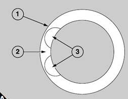
|
|
|
|
is given below:
1 Fasten securely the cylinder head on a milling
machine, and use a slot drill of approximately 10 mm
seat insert (A3). The depth of the slots should be 0,50
mm (0.020 in) less than the depth of the valve seat
insert. The minimum depth of the insert is 7,95 mm
(0.313 in). The slots should be apart by approximately
to within 0,5 mm (0.020 in) of the outside diameter of
the insert.
2 Use a flat chisel, at the point which is indicated by
the arrow (A2) and in the direction of the opening in
the insert, to break the insert. Do not damage the
recess during this operation.
3 Remove the insert and check that the recess is
clean and that there is no damage.
Special tools:
Valve seat tool, 21825 841
Valve seat cutter, 21825 842
Drive handle, 21825 861
Tool to insert valve seat, 21825 867
Holder for rolling tool, 21825 892
Rolling tool, 21825 894
1 Valve seat inserts are available in two sizes,
oversize and standard. The oversize inserts are 0,05
mm (0.002 in) larger on the outer diameter. If an
oversize insert is to be fitted, ensure that it has the
correct part number: CV 14128 for an inlet seat or OE
47574 for an exhaust seat. Check also that the wall of
the recess in the c ylinder head will maintain the
correct interference fit, as given on page 59.
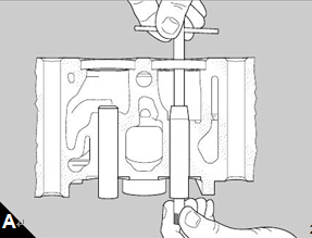
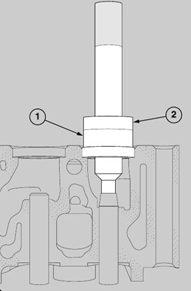
2 Cool the valve seat insert in liquid nitrogen to -35°C
(-31°F). Use the special tool, 21825 867, (B1) and the
B
226
handle, 21825 861 (B2), to fit the relevant insert into
its recess as rapidly as possible.
3 Use a 0,04 mm (0.0015 in) feeler gauge to check
that the bottom of the new insert is in full contact with
the bottom of the recess.
If a new valve seat insert has been fitted for an
exhaust valve, the edge of the casting of the cylinder
head must be rolled over the chamfer which is around
the circumference of the insert. Proceed as follows:
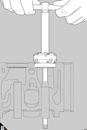
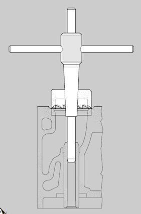
4 Fasten securely the cylinder head on a suitable drill
machine with the flame face in the upper position and
fit the rolling tool, 21825 894, and holder, 21825 892,
to the machine. 帕金斯u5lt0317缸垫,沃尔沃720引擎配件,珀金斯柴油发电机ECU,卡特柴油发电机ECU,沃尔沃柴油发电机ECU,威尔信P2000E 备件,威尔信P2000E 大修备件
400-100-8969 15088860848
0574-26871589 15267810868
0574-26886646 15706865167
0574-26871569 18658287286
