 English
 Espaol
 Franais
 阿拉伯
阿拉伯 中文(简)
中文(简) Deutsch
 Italiano
 Português
 日本
日本 韩国
韩国 български
 hrvatski
 esky
esky Dansk
Dansk Nederlands
 suomi
suomi Ελληνικ
 印度
印度 norsk
norsk Polski
 Roman
Roman русский
 Svenska
英国帕金斯柴油发动机柴油发电机组机油泵
英国帕金斯柴油发动机柴油发电机组机油泵
Lubricating oil pump
润滑油泵
5 Remove the clip which fastens the suction pipe and
5删除剪辑使吸水管和
the integral strainer to its support bracket, and remove
其支架的整体过滤器,去除
the two bolts which retain the suction pipe on the
两根螺栓,它保留在
lubricating oil pump.
润滑油泵。
6 If relevant to other work on the engine, remove the
6如果与其他相关工作的发动机,拆卸
two bolts which retain the support bracket to the No.3
两根螺栓将支撑托架保留至3号
main bearing cap.
主轴承盖。
1 For early engines with sump adaptors, remove
1与槽适配器早期的发动机,拆卸
the lubricating oil sump, operation 19-1.
润滑油槽,运行19-1。
2 Remove the plug on the ’B’ bank side of the sump
2将插头上的插头卸下
adaptor and withdraw the bobbin (A8) from the
适配器和撤回筒管(A8)从
discharge side of the lubricating oil pump.
润滑油泵排出侧。
3 Remove the four bolts (A15) and the washers which
3拆下四个螺栓和垫圈(A15)
retain the lubricating oil pump on the crankcase. Lift
在曲轴箱上保留润滑油泵。电梯
away the lubricating oil pump from its dowels.
把润滑油从其销。
4 For new engines, remove the single piece
4为新发动机,拆卸单块
lubricating oil sump, operation 19-5.
润滑油槽,运行19-5。
If the lubricating oil pump is to be renewed, or to be
如果润滑油泵要换新,或是
dismantled, it would be an advantage to remove the
拆除,这将是一个优势,以消除
drive gear before the lubricating oil pump is removed
在机油泵被拆前,传动齿轮
from the crankcase, operation 19-8 paragraph 1.
从曲轴箱,操作打款1。
Remove the four bolts (A15) and the washers which
拆下四个螺栓和垫圈(A15)
retain the lubricating oil pump on the crankcase. Lift
在曲轴箱上保留润滑油泵。电梯
away the lubricating oil pump from its dowels.
把润滑油从其销。
To fit
1 For early engines with sump adaptors, ensure
that the dowels in the crankcase are fitted correctly
and put the assembly of the lubricating oil pump
against the crankcase with the drive gear in mesh with
its idler gear. Fit new spring washers to the four bolts
which retain the lubricating oil pump and apply ’Loctite
575’ to the threads of the bolts. Fit and tighten the
bolts to a torque of 55 Nm (40 lbf ft).
2 Renew the ’O’ rings (page 142/A11) on the bobbin
which is fitted between the suction side of the
lubricating oil pump and the base of the sump. Renew
the ’O’ rings (page 142/A7,9) on the bobbin, which is
fitted to the discharge side of the lubricating oil pump,
and also on the plug which is to be fitted to the ’B’
bank side of the sump adaptor.
3 Slide the bobbin for the discharge side through the
sump adaptor and into the outlet of the pump, with the
short extension at the outer end. Fit the plug to the ’B’
bank side of the sump adaptor. Insert the two bolts,
complete with new spring washers, and tighten
securely.
4 Fit the lubricating oil sump, operation 19-1.
5 For new engines, with a single piece lubricating
oil sumps, ensure that the dowels in the crankcas e
are fitted correctly and put the assembly of the
lubricating oil pump against the crankcase. Fit new
spring washers to the four bolts which retain the
lubricating oil pump and apply ’Loctite 575’ to the
threads of the bolts. Fit and tighten the bolts to a
torque of 55 Nm (40 lbf ft).
6 If relevant, fit the drive gear onto the drive shaft of
the lubricating oil pump to mesh with its idler gear,
followed by a new locking washer. Apply ’Loctite 241’
to the threads of the shaft and fit the nut which retains
the drive gear. Tighten the nut to a torque of 120 Nm
(88 lbf ft). If necessary, turn the nut further, just
enough for the locking washer to be bent up onto a
corner or a flat side of the nut. Bend up the locking
washer.
7 If relevant, fit the support bracket for the suction
pipe to the No.3 main bearing cap. Fit the two bolts,
complete with new spring washers, and tighten to a
torque of 23 Nm (17 lbf ft). Ensure that the vertic al
section of the support bracket is to the rear of the two
bolts.
8 Assemble the flange of the suction pipe to the
lubricating oil pump with a new joint and fit the two
bolts, complete with new spring washers. Tighten the
two bolts to a torque of 23 Nm (17 lbf ft).
9 Assemble the clip which fastens the suction pipe
and the integral strainer to its support bracket, apply
’Loctite 542’ to the threads of the ’U’ bolt and fit the
nuts, complete with new spring washers.
10 Fit the lubricating oil sump, operation 19-5.
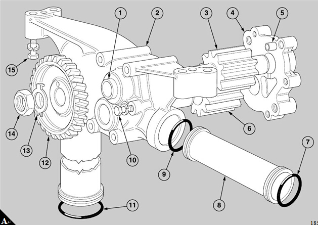
Refer to the illustration (A) on page 142.
1 Remov e the nut (A14) and the locking washer
(A13) which retain the drive gear (A12). Use suitable
puller to withdraw the drive gear.
2 Remov e the s ix bolts (A10) which retain the end
cover (A4) to the body of the pump (A2) and use a soft
faced hammer to remove the end cover.
3 Withdraw the axle of the driven rotor, the driven
rotor (A6), the driving rotor (A3) and its integral drive
shaft from the body of the pump.
To assemble
1 Ensure that the ring type dowel (A5) in the body is
fitted into its counterbore in the relevant bolt hole of
the end cover, and put the end cover onto the drive
shaft. Insert the six bolts, complete with new spring
washers, and tighten evenly the bolts to a torque of 21
Nm (15 lbf ft). Check that the drive shaft rotates freely
in the casing.
2 Fit the driv e gear onto the drive shaft, followed by a
new locking washer. Apply ’Loctite 241’ to the threads
of the shaft and fit the nut which retains the drive gear.
Hold the drive gear in a vice with soft covers and
tighten the nut to a torque of 120 Nm (88 lbf ft). If
necessary, turn the nut further, just enough for the
locking washer to be bent up onto a flat side of the nut.
Bend up the locking washer.
英国帕金斯柴油发动机柴油发电机组机油泵清洁检查
19-9
19-9
19
十九
1 Wash all the components in kerosene and dry them
1清洗煤油中所有的成分,并将其擦干
with compressed air.
压缩空气。
2 Inspect carefully the casing, the end cover, the
2检查外壳、端盖、
rotors and the bearing surfaces for wear. Small
转子和轴承表面的磨损。小
marks or damage and roughness may be removed
可以删除标记或损坏和粗糙度
carefully with an oilstone. Renew all worn
用油石仔细。更新所有穿
components.
组件。
3 If the bearings are to be renewed, press out the old
3如果轴承被更换,按旧
bushes (page 142/A1) and insert the new bushes,
灌木(142页/ A1)和插入新的灌木,
with the openings at the ends of the oil grooves
在油槽末端的开口处
toward the spur gears. Press in each bush until the
向直齿轮。压在每一个灌木丛中
end is aligned precisely with the casing, or with the
末端与套管的精确对准,或与
inner face of the end cover, as relevant.
内表面的端盖,有关。
4 Fit the axle for the driven rotor to its bore in the
4将驱动转子的轴安装到其孔中
casing and fit the driven rotor onto the shaft. Use a
套管,将从动转子安装到轴上。使用
straight edge and a set of feeler gauges to check the
直边和一套塞尺检查
clearance between the gear and the end fac e of the
齿轮和结束的FAC E之间的间隙
casing. The clearance must be between 0,175 and
套管。间隙必须介于0175和
0,250 mm (0.007 and 0.010 in).
0250毫米(0.007和0.010)。
5 Assemble the pump without the ring type dowel and
5组装泵无环式定位和
tighten lightly the six bolts. Use a dial test indicator to
轻轻地拧紧六个螺栓。使用拨号测试指示器
check the end float of the drive shaft. The permissible
检查传动轴的端浮。允许
end float is 0,175 to 0,250 mm (0.007 to 0.010 in).
最终的浮动是0175至0250毫米(0.007至0.010英寸)。
Remove the end cover.
拆下端盖。
400-100-8969 15088860848
0574-26871589 15267810868
0574-26886646 15706865167
0574-26871569 18658287286
