 English
 Espaol
 Franais
 阿拉伯
阿拉伯 中文(简)
中文(简) Deutsch
 Italiano
 Português
 日本
日本 韩国
韩国 български
 hrvatski
 esky
esky Dansk
Dansk Nederlands
 suomi
suomi Ελληνικ
 印度
印度 norsk
norsk Polski
 Roman
Roman русский
 Svenska
帕金斯柴油发动机机油冷却器3012维修保养技术参数资料
帕金斯柴油发动机机油冷却器3012维修保养技术参数资料
Heat exchanger (oil to coolant) - early
热交换器(润滑油)-早期
1 Remov e the drain plug from under the outlet
1移除螺塞从下口
connection of the coolant pump and drain the coolant
冷却液泵的连接和排空冷却液
of the engine into a suitable container. Place another
发动机变成一个合适的容器。另一个地方
suitable container below, and to the rear of, the
合适的容器下面,和后面的
lubricating oil filters. Remove the drain plug at the
润滑油过滤器。拆下排水塞
rear of the heat exchanger to drain the engine
换热器后部的发动机
lubricating oil. Use the strap wrench, 21825 825, to
润滑油。使用带扳手,825 21825,以
remove the filter canisters (A6).
拆下过滤罐(A6)。
2 Release the hose clips and remove the delivery
2松开软管卡子并拆下输送
pipe between the front end of the tube stack and the
管之间的管和管的前端
coolant gallery of ’B’ bank.
'乙'银行的冷却液库。
3 Release the hose clips and slide the hose at the
3松开软管卡子并将软管滑到
inlet for the coolant away from the rear end of the tube
冷却液从管的后端的入口
4 Remove the s ix bolts (A5) which retain the heat
4取出6螺栓(A5),保留热量
exchanger and lift the assembly away from its
换热器,并从其
mounting adaptor.
安装适配器。
1 Fit a new hose, and the two hose clips, onto the end
1安装一个新的软管和软管卡子,到最后
of the pipe on the discharge side of the coolant pump.
在冷却液泵的排出侧管中的管道。
2 Check that four new ’O’ rings (A1) are fitted into
2检查四个新的O型圈(A1)是装在
their locations in the joint face of the heat exchanger
换热器接头面位置
and ensure that the ’O’ rings remain in their positions
确保'澳'戒指留在他们的位置
during the operation. Use suitable guide studs, which
在操作过程中。使用合适的导向螺柱
are made locally, to fit the assembly of the heat
都是在本地制造的,以配合装配的热量
exchanger to the adaptor. Insert the six bolts,
适配器换热器。插入六个螺栓,
complete with plain and spring washers, and tighten
用平和弹簧垫圈完成,并拧紧
them evenly and securely.
它们均匀且安全地。
3 Fit a new hose and the two hose c lips onto the
3安装一个新的软管和软管的嘴唇上的
coolant elbow on the discharge side of the heat
热端的冷却液弯头
exchanger.
换热器。
Check that the faces of the inlet to the coolant gallery
检查进冷却液库的入口的面
and the flange of the inlet pipe are clean. Use a new
和进口管的法兰是干净的。使用一个新的
gasket and fit the pipe to the coolant gallery, insert the
垫片,安装到冷却液管内,插入
four bolts, complete with plain washers and new
四个螺栓,用平垫圈和新的
spring washers, and tighten securely.
弹簧垫圈,并牢固地紧固。
Slide the two hoses over the junctions of the pipes
and align and tighten the four hose clips.
5 Fill three new filter canisters with clean engine
lubricating oil and fit them onto the adaptors on the
heat exchanger until the rubber sealing rings are just
in contact with the s eats of the housing. Tighten each
canister a further /4 turn by hand. Do not overtighten
the canisters.
6 Fit the drain plug for the engine lubricating oil.
7 If the engine lubricating oil c an be used again,
return it to the sump and fill the sump with new and
clean oil to the ’Full’ mark on the dipstick, if necessary.
8 Check that the drain plugs for coolant are secure
and fill the cooling system. Add more coolant, of the
same specification as that already in use, if
necessary.
To dismantle and to assemble 19-11
To dismantle
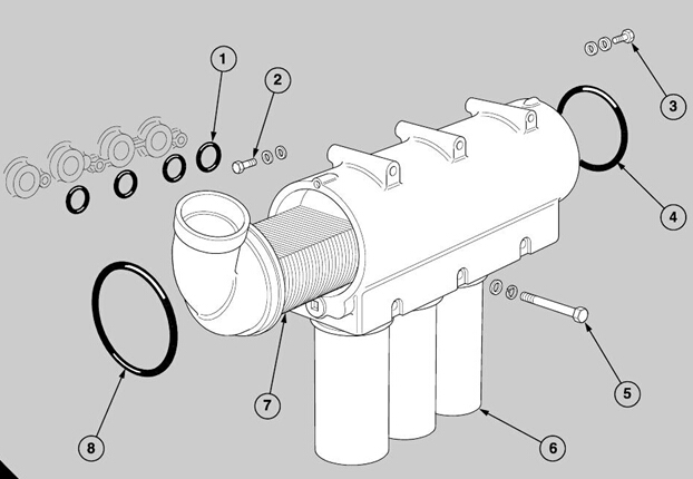
Refer to the illustration (A) on page 145.
1 Remove the two small bolts (A2 and A3) and the
washers which retain the tube stack (A7) in the
housing. Push the tube stack to the rear and remove
the ’O’ ring (A4) from its groove in the rear end of the
tube stack. Push the tube stack forward and out of
the housing and remove the second ’O’ ring (A8).
Caution: Do not push out the tube stack before the
’O’ ring is removed from the rear end of the tube stack
because the ’O’ ring will not move past the passages
in the housing. If the tube stack is tight in the housing,
it may be released by the use of a suitable piece of
soft wood. Put the piece of wood through the opening
of the coolant inlet and in contact with the end of the
tubes. Use gently a hammer on the end of the wood
to expel the tube stac k from its housing. Do not hit
the thin casing at the end of the tube s tack to release
the tube stack.
To assemble
1 Apply some engine oil to the bore at both ends of
the housing.
2 Fit a new ’O’ ring to the groove at the front end of
the tube stac k. Insert the tube stack into the front end
of the housing. Align correctly the bolt holes for the
two small bolts and the washers which retain the tube
stack in the housing, and push the tube stack through
enough to show the groove at the rear end.

3 Fit a second new ’O’ ring to the groov e and push
carefully the tube s tack into its correct position. Insert
the two small bolts, with plain washers and new spring
washers, to retain the tube stack in the housing.
Tighten securely the bolts.
To clean and to inspect
To clean
1 After the removal of the tube stack, check that the
tubes are clean and are not damaged.
2 Wash the tube stack in k erosene and ensure that
the fins are not damaged. Dry inside the tubes with
compressed air and then wash the tube stac k in hot
water.
3 To loosen hard deposits in the tubes, soak the tube
stack in a solution which is made with a proprietary
brand of inhibited sulphamic acid. The solution must
be made and used in accordance with the
manufacturer’s instructions. When the action of the
solution is finished, dip the tube stack in a solution
made of 0,5 kg (1 lb) of sodium carbonate to 25 litres
(5 imp. gallons) of hot water. The final operation is to
dry inside the tubes with compressed air.
4 Clean the housing of the heat exchanger in a
solvent which is not caustic, and wash in hot water.
To inspect
1 Check the housing for damage and scratches.
Inspect the tube stac k for corrosion, for cracks and for
damage. The tube stack should be tested also under
pressure. Close one end of the pack and apply air to
the tubes at 2,11 kg/m (30 lbf/in ), with the pack
immersed in water at 80°C.
To remove and to fit
1 Remov e the heat exchanger, operation 19-10.
2 Release the two bolts which retain the elbow of the
delivery pipe to the crankcase. Slide the delivery pipe
out of the outlet at the rear end of the mounting
adaptor and remove the elbow from the delivery pipe.
Discard the ’O’ rings.
3 Disconnect the delivery pipes which supply the fuel
injection pump and the two turbochargers with
lubricating oil.
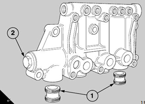
4 Remov e the relief valve (A2), operation 19-17.
5 Release the bolts which retain the mounting
adaptor and lift up the assembly away from the
crankcase. Keep the two bobbins (A1).
6 Clean thoroughly the mounting adaptor with
kerosene and dry with compressed air. Inspect for
cracks or other damage and remove all of the debris
which may remain in the connections.
To fit
1 Use clean engine lubricating oil to lubricate the
locations of the two bobbins in the base of the
assembly of the mounting adaptor for the heat
exchanger.
2 Fit new ’O’ rings to each of the bobbins and press
the bobbins into the recesses in the assembly (A). Oil
lightly the recesses for the bobbins in the sump
adaptor, hold the assembly of the mounting adaptor
on the side wall of the crankcase and press it
downward to engage the bobbins in the sump
adaptor.
3 Fit the six bolts, with plain and spring washers, to
retain the assembly and tighten them securely.
4 Fit the relief valve, operation 19-17.
5 Fit the heat exchanger, operation 19-10.
Heat exchanger (oil to coolant)
To remove and to fit
Special tools:
Strap wrench, 21825 825
1 Fit a new hose, and the two hose clips, onto the end
of the pipe on the discharge side of the coolant pump.
2 Ensure that the two bobbins which fit in the heat
exchanger are clean. Fit new ’O’ rings to the grooves.
3 Apply clean engine lubricating oil to the ’O’ rings
and fit the bobbins to their respective bores. The long
bobbin is fitted in the elbow connector and the short
bobbin is fitted in the lubricating oil sump.
4 Hold the body of the heat exchanger over the two
bobbins and move the body downward carefully to
1 If relevant, remove the air duct, from between the
turbocharger on ’B’ bank and the air charge cooler, for
access to the heat exchanger.
2 Remove the drain plug from the outlet connection
of the coolant pump and drain the coolant of the
engine into a suitable container. Put another suitable
container below and to the rear of, the lubricating oil
filters. Remove the drain plug at the rear of the heat
exchanger to drain the engine lubricating oil. Use the
strap wrench, 21825 825, to remove the filter
canisters.
3 Release the hose clips and remove the delivery
pipe between the front end of the tube stack and the
coolant gallery of ’B’ bank.
4 Release the hose clips and slide the coolant hose
away from the rear end of the tube stack.
5 Remove the elbow at the rear of the crankcase,
which is the inlet for the lubricating oil to the main oil
gallery, and withdraw the delivery pipe from the body
of the heat exchanger.
6 Remove two bolts to disconnect, at the crankcase,
the drain pipe for the lubricating oil from the
turbocharger of ’B’ bank, and move the pipe away for
access to the body of the heat exchanger.
7 If necessary, remove the relief valve, operation 19-
Remove the four bolts which retain the heat
exchanger, lift up the body of the heat exchanger to
disengage the two bobbins which connect with the
lubricating oil sump and remove it from the engine.
engage the bobbins in the bores of the heat
exchanger.
5 Fit the four bolts which retain the heat exchanger to
the crankcase and tighten securely.
6 If relevant, fit the relief valve, operation 19-17.
7 Fit the drain pipe for lubricating oil between the
turbocharger of ’B’ bank and the crankcase. Retain
with the two bolts and use a new joint.
8 If necessary renew the ’O’ rings of the delivery pipe
for the lubricating oil, and insert the pipe into the body
of the heat exchanger. Insert the other end of the pipe
into the elbow and fit the elbow to the rear of the
crankcase. Use a new joint and retain with two bolts
with plain and spring washers.
9 Fit a new hose, and the two hose clips, onto the
coolant elbow on the discharge side of the heat
exchanger.
10 Check that the faces of the inlet to the coolant
gallery and the inlet pipe flange are clean. Use a new
joint and fit the pipe to the coolant gallery, insert the
four bolts, complete with plain washers and new
spring washers, and tighten securely.
11 Slide the two hoses over the junctions of the pipes
and align, and tighten the four hose clips.
12 Fit the drain plug for engine lubricating oil to the
rear of the heat exchanger and check that it is secure.
13 Fill three new filter canisters with clean enginelubricating oil and fit them on to the adaptors on the
heat exchanger until the rubber sealing rings are just
in contact with the seats of the housing. Tighten each
canister a further /4 turn by hand. Do not overtighten
the canisters.
14 If the engine lubricating oil can be used again,
return it to the sump of the engine and fill the sump
with new and clean oil to the ’Full’ mark on the
dipstick, if necessary.
15 Check that the drain plugs for coolant are fitted
and secure. Fill the cooling system and add more
coolant, of the same specification as that already in
use, if necessary.
16 If relevant, fit the air duct from the turbocharger on
’B’ bank to the air charge cooler.
To dismantle and to assemble To dismantle
1 Remov e the two small bolts (A2 and A3) and the
washers which retain the tube stack (A7) in the
housing.
Push the tube stack to the rear and remove the ’O’
ring (A4) from its groove in the rear end of the tube
stack. Push the tube stack forward and out of the
housing and remove the second ’O’ ring (A8).
Caution: Do not push out the tube stack before the
’O’ ring is removed from the rear end of the tube stac k
because the ’O’ ring will not move past the passages
for the lubricating oil in the housing. If the tube stack
is tight in the housing, it may be released by the use
of a suitable piece of soft wood. Put the piece of wood
through the opening of the inlet for the c oolant and in
contact with the end of the tubes. Use gently a soft
faced hammer to expel the tube stack from its
housing. DO NOT hit the thin casing at the end of the
tube stack to releas e the tube stack.
To assemble
1 Apply some engine oil to the bore at both ends of
the housing.
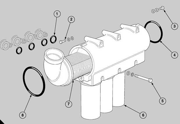
2 Fit a new ’O’ ring to the groove in the front end of
the tube stac k. Insert the tube stack into the front end
of the housing. Align correctly the bolt holes for the
two small bolts and the washers which retain the tube
stack in the housing, and push the tube stack through
enough to show the groove in the rear end.
3 Fit a second new ’O’ ring into the groove and push
carefully the tube stack into its correct position. Insert
the two small bolts, with the plain washers and new
spring washers, which retain the tube stack in the
housing. Tighten securely the bolts.帕金斯柴油发动机机油冷却器3012清洁和检查
To clean
1 After the removal of the tube stack, chec k that the
tubes are clean and are not damaged.
2 Wash the tube stack in k erosene and ensure that
the fins are not damaged. Dry inside the tubes with
compressed air and then wash the tube stack in hot
water.
3 To loosen hard deposits in the tubes, soak the tube
stack in a solution which is made with a proprietary
brand of inhibited sulphamic acid. The solution must
be made and used in accordance with the
manufacturer’s instructions. When the action of the
solution is finished, dip the tube stack in a solution
made of 0,5 kg (1 lb) of sodium carbonate to 25 litres
(5 imp. gallons) of hot water. The final operation is to
dry inside the tubes with c ompressed air.
4 Clean the housing of the heat exchanger in a
solvent which is not caustic, and wash in hot water.
To inspect
1 Check the housing for damage and scratches.
Inspect the tube stac k for corrosion, for cracks and for
damage.
2 The tube stack should be tested also under
pressure. Close one end of the pack and apply air to
the tubes at 2,11 kg/m (30 lbf/in ), with the pac k
immersed in water at 80°C.
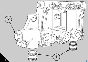
To remove and to fit
1 The illustration (A) shows the location of the relief
valve for early engines: in the mounting adaptor for
the heat exchanger. On new engines, the location of
the relief valve is near the c rankcase in the lower rear
end of the heat exchanger. The same type of relief
valve is used for both locations.
To remove
A
184
1 Remov e the c ap (A2) and withdraw the assembly
of the relief valve. Check the plunger and the housing
for scratches and for damage. If the scratches are
deep, the complete assembly must be renewed.
To fit
Caution: To ensure that the opening pressure is
correct, always fit a new spring.
1 Check the spring for distortion, and measure its free
length. A new spring conforms to the requirements
given below:
Free length 123,2 mm (4.85 in)
Length under load of
39,5 kgf (87 lbf) 74,0 mm (2.91 in)
2 Lubricate lightly the plunger and ensure that it
slides freely in the bore of the casing. Insert the
spring. Fit the cap, with a new c opper washer, and
tighten it securely.
400-100-8969 15088860848
0574-26871589 15267810868
0574-26886646 15706865167
0574-26871569 18658287286
