 English
 Espaol
 Franais
 阿拉伯
阿拉伯 中文(简)
中文(简) Deutsch
 Italiano
 Português
 日本
日本 韩国
韩国 български
 hrvatski
 esky
esky Dansk
Dansk Nederlands
 suomi
suomi Ελληνικ
 印度
印度 norsk
norsk Polski
 Roman
Roman русский
 Svenska
帕金斯柴油发动机燃油泵、喷油器、滤清器燃油系统的谈细参数与维修保养技术参数资料
帕金斯柴油发动机燃油泵、喷油器、滤清器燃油系统的谈细参数与维修保养技术参数资料
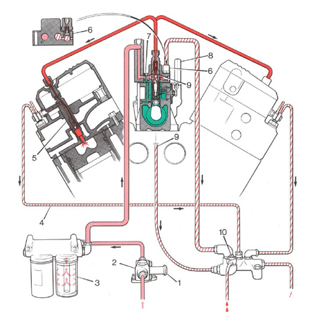
perkins帕金斯3012柴油发动机燃油系统的组成
General description
一般描述
The fuel injection pump is a 12 element in-line unit
燃油喷射泵是一个12元列单元
driven at 0.5 x engine speed by the timing gears. It is
在0.5×发动机转速的定时齿轮驱动。它是
fitted to a plate in the crankcase ’V’.
安装在曲轴箱中的一个板上。
A constant s peed governor, integral with the fuel
恒速调速器,与燃料积分
injection pump, maintains engine speed through the
喷油泵,保持发动机转速通过
engine load range. The stop control on the governor
发动机负荷范围。总督的停止控制
is connected directly to a solenoid, which is actuated
直接连接到一个电磁线圈,这是致动的
by the stop button and the protection devices of the
通过停止按钮和保护装置
engine. A vernier control is connected to the lever of
发动机。游标控制连接到杠杆
the speed control for fine adjustment of engine speed.
发动机转速精细调节的速度控制。
The end c overs on the ’CS’ governors are of variable
C端接管的CS的州长是可变的
designs, according to the application. Each cover
设计,根据应用。每个盖
includes an assembly of a servo-valve and, where a
包括一个伺服阀组件,在那里
ramp is used which is not adjustable, the ramp is
坡道是使用,这是不可调,坡道是
fastened to the inner wall of the cover. Additional
系在盖的内壁上。额外的
differences are the positions for the connections for
差异是连接的位置
the inlet (A1) and the outlet (A3) of the lubricating oil.
入口(A1)和出口(A3)的润滑油。
Where necessary, a plug is fitted to give access for
在需要的地方,安装一个插头以使接入
the adjustment of the ramp (A2).
坡道的调整(A2)。
As seen from the rear of the engine, the shaft of the
从发动机的尾部看,轴的
fuel injection pump rotates anti-clockwise. The pump
喷油泵逆时针旋转。泵
elements operate in the sequence given below:
在下面给出的序列中的元素:
1, 9, 4, 11, 2, 7, 6, 10, 3, 8, 5 and 12 at 30 degree
30,9,4,11,2,7,6,10,3,8,5,12,1
intervals, with No.7 element at the point of spill cutoff
间隔7元在泄漏截止点
(A6 injection).
(A6注射)。
The high-pressure fuel pipes are made from special
高压燃料管是由特殊的
steel 8 mm diameter x 2 mm bore. Zinc plated nuts
钢8毫米直径2毫米口径。镀锌螺母
and collars are fitted on both ends of each pipe. The
和衣领都装在两端的每个管道。这个
relevant cylinder number is stamped on the nut at the
有关汽缸编号是在螺母上加盖
pump end of the pipe.
管道泵端。
The low-pressure system of fuel pipes is made from
燃油管的低压系统是由
mild steel, with connections of union nuts and
轻微的钢,与连接螺母和
sleeves.
袖子。
For early engines, the lift pump is driven by a cam on
对于早期的发动机,电梯泵是由凸轮驱动的
the rear end of the auxiliary drive shaft. On new
辅助驱动轴的后端。在新的
engines, the fuel lift pump is mounted at the front end
发动机,燃油泵安装在前端
of the engine within the engine vee and is driven by
该发动机在发动机和驱动的V型
an additional cam lobe on the ’B’ bank camshaft. The
“乙”银行凸轮轴上的凸轮轴。这个
lift pump draws fuel through a primary filter from the
提升泵从所用的主过滤器中抽油
fuel tank before directing it through two filter canisters
燃料箱前引导它通过两个过滤罐
to the gallery of the fuel injection pump.
燃油喷射泵的图库。
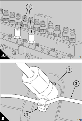
Two low-pressure relief valves (A1) are fitted on the
body of the fuel injection pump. They keep a constant
pressure of 90 to 117 kN/m (13 to 17 lbf/in ) in the
fuel supply to the gallery of the pump and allow the
surplus fuel to return to the fuel tank. Fuel enters the
elements of the fuel injection pump and is sent at high
pressure, by the elements, to the 12 ’low s pring’ type
of fuel injectors. The fuel injectors are set to operate
at 243 bar (240 atmospheres).
Early engines are fitted with Bosch or OMAP fuel
injectors. New engines are fitted with composite
rocker covers and these have Stanadyne fuel
injectors, as shown (B).
These fuel injectors are longer than the other types to
allow the leak-off banjo connections to be fitted
directly to the bodies of the fuel injec tors above the
composite rocker covers. Other details are generally
similar to the Bosch and the OMAP fuel injectors.
From the leak-off banjo connections a system of pipes
directs the leak-off fuel to a connection block where it
mixes with the spill fuel and the surplus fuel from the
fuel injection pump. It is then returned to the fuel tank.
The connection block has a vent plug for the low-
pressure fuel system. For new engines the
connection block is part of the fuel filter head.
Clean thoroughly each component, and the area
around it, before it is dismantled or removed.
Fit suitable caps and plugs to all of the unions
immediately after they have been dis connected.
Components must be absolutely clean and kept
safely until they are used during the maintenance or
the overhaul of the fuel system.
如何清洗帕金斯柴油初级燃油滤清器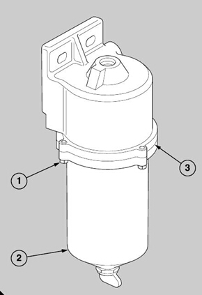

Primary fuel filter
How to clean the primary fuel filter
1 Remove the three bolts (A1) and remove the filter
bowl (A2).
2 Clean all of the components with paraffin and dry
them with a compressed air jet.
3 Fit the bowl to the filter head, together with a new
sealing ring. Align the clamp ring (A3) and fasten it
with the three bolts.
Early engines can be fitted with filters which have
elements that can be cleaned. These elements
should be removed, cleaned with fuel oil and dried
with a compressed air jet.
Fuel filter canisters
How to renew the canisters
of the main fuel filter
On new engines the main fuel filter is fitted at the rear
of the engine on the ‘A’ bank side. For early engines
it is fitted to the 'B' bank side, against the cover of the
coolant gallery as shown (B). The filter has two
disposable canisters. Both canisters must be
renewed at the same time.
1 Clean the area around the filter and remove the fuel
filter canis ters. If neces sary, use a strap wrench.
Discard the canisters.
2 Check that the sealing ring (B1) is fitted correctly to
each new canister and clean the contact faces of the
filter head.
3 Lubricate the top of the canister seal (B1) with clean
fuel oil and renew the sealing ring (B2) on the adaptor.
4 Fit the new canisters to their threaded adaptors and
tighten each canister until the sealing ring just comes
into contact with the filter head. Continue to tighten
overtighten.
After the fuel filter canisters have been renewed,
eliminate air from the low pressure fuel system as
given in operation 20-16.
Fuel filter head
The fuel filter head is fitted at the rear of the engine
on the ’A’ bank side. For early engines the fuel filter
head is fitted to the ’B’ bank side, against the cover of
the coolant gallery.
To remove
1 Remov e the two fuel filter canisters.
Caution: Do NOT bend any of the fuel pipes.
2 Disconnect the fuel leak-off pipes from the fuel filter
head. Remove the pipes if relevant to the job.
3 Disconnect the three low pres sure fuel pipes from
the fuel filter head. Remove the pipes if relevant to
the job.
4 Hold the fuel filter head and remove the two bolts
and nuts. Withdraw the bolts and collect the spacers
and washers.
To fit
1 Fit the fuel filter head to the air filter bracket and
retain it with the two bolts and nuts complete with
spacers and plain and spring washers. The spacers
must be fitted between the fuel filter head and the air
filter bracket. Tighten the nuts to a torque of 23 Nm
(17 lbf ft).
2 Fit the three low pressure fuel pipes. Use new
copper sealing washers.
3 Fit the fuel leak-off pipes. Use new copper sealing
washers.
4 Fit the two fuel filter canisters, see operation 20-2.
5 Eliminate air from the low pressure fuel system as
given in operation 20-16.
400-100-8969 15088860848
0574-26871589 15267810868
0574-26886646 15706865167
0574-26871569 18658287286
