 English
 Espaol
 Franais
 阿拉伯
阿拉伯 中文(简)
中文(简) Deutsch
 Italiano
 Português
 日本
日本 韩国
韩国 български
 hrvatski
 esky
esky Dansk
Dansk Nederlands
 suomi
suomi Ελληνικ
 印度
印度 norsk
norsk Polski
 Roman
Roman русский
 Svenska
帕金斯柴油发动机交流充电发电机维修技术资料
帕金斯柴油发动机交流充电发电机维修技术资料
Alternator
交流发电机
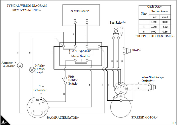
The three phase (star connected) alternator is of the
三相(星形连接)交流发电机的
rotating field and stationary armature (stator) type (A).
旋转磁场和固定电枢(定子)类型(一)。
The rectifier consists of six silicon diodes. These are
整流器由六个硅二极管组成。这些都是
retained by the two heat sinks in the assembly of the
由两个散热片保留在组装
rectifier, which is in the housing at the slip ring end.
整流器,这是在外壳的滑动环结束。
Excitation of the field is done by three auxiliary diodes
励磁的领域是由三个辅助二极管
which are assembled in the centre of the rectifier.
这是在整流器中心组装。
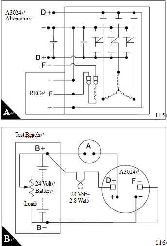
The output is controlled by an integral regulator and
输出是由一个积分调节器和控制
the maximum rated output (hot) is 32 amps at 28
最大额定输出(热)是32安培在28
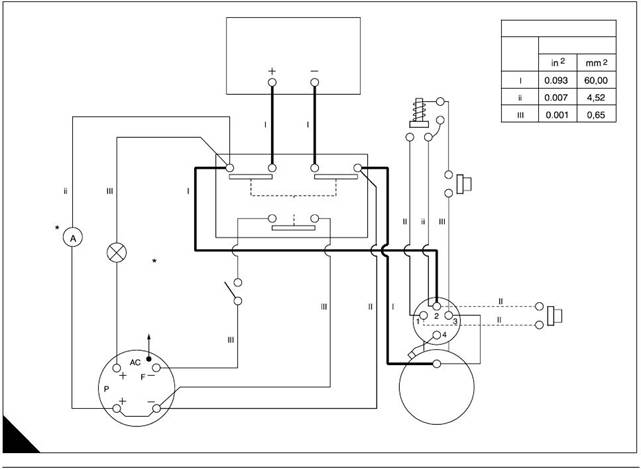
volts. A diagram of connections for a suitable
伏。一个合适的连接图
dynamic test rig is shown (B).
动态试验台(乙)。
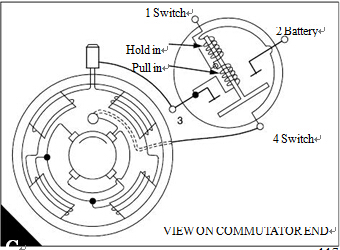
Starter motor
The heavy-duty starter motor is flange mounted and
is operated by a 24 volt electrical supply. A solenoid
type of start switch is fitted on the outside of the
starter motor (C). The plunger of the switch also
actuates, by the use of a screw link and a shift lever,
the assemblies of the armature and the pinion. The
assembly of the pinion includes a device to ensure its
engagement, a clutc h to ensure that the motor is not
overloaded, and a device for free rotation in one
Operation of the start button energises two windings
around the plunger of the solenoid. One winding pulls
the plunger which causes the shift lever to move the
pinion of the starter motor into mesh with the s tarter
ring. The other winding holds the plunger to ensure
that the pinion remains in mesh. If the teeth of the
pinion do not engage immediately, the pinion moves
backward against its spring and there is a small
amount of rotation until the engagement occurs. The
start switch operates when the pinion is engaged.
The electrical current then flows directly from the
battery to the starter motor. This circuit is parallel to
the circuit through the winding which pulls the
plunger, and the flow of current through the winding is
stopped. The winding which holds the plunger
continues to be energised until the start button is
 A device for free rotation in one direction is included
in the assembly of the pinion to prevent damage to the
armature, the teeth of the pinion and the teeth of the
starter ring when the engine starts. When the start
button is released, a spring withdraws the pinion
along the splined shaft of the armature to its original
position.
Warning/engine stop switches
Two switches are included in the cooling system and
the lubrication sy stem. They give protection to the
engine if the coolant temperature or the oil pressure
exceed the permissible limits. Certain engines have
an extra switch whic h gives protection to the engine if
the coolant level is below a certain limit.
The switches operate, according to the circuits for
specific applications, if there is an increase in the
temperature of the coolant or if there is a decrease in
the pressure of the engine lubricating oil.
The switches are set at the factory to operate within a
selected range of temperatures and pres sures. Do
not try to alter the settings. No maintenance is
necessary for the switches except to check at
intervals for their correct operation.
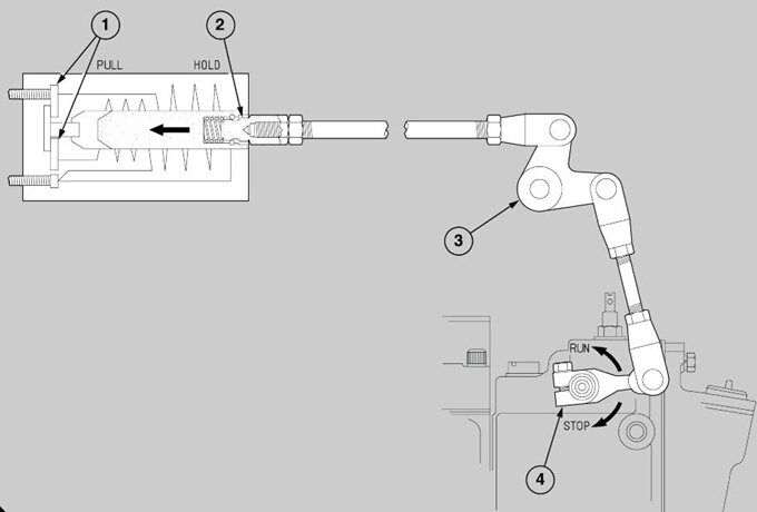
Stop solenoid
The stop solenoid, which is generally for an ’energise
to run’ system, is fitted on the inner wall of the
induction manifold of ’A’ bank. The stop solenoid is
connected by a spherical coupling (A2), through a bell
crank lever (A3) and linkage, to the stop control lever
(A4) on the governor.
When the stop solenoid is energised, the two circuits
in the windings of the solenoid actuate a plunger
which moves the lever of the stop control to the ’RUN’
position. One winding pulls the plunger in the
direction of the arrow until the internal switch contacts
(A1) are separated. The circuit through the winding is
then broken but the other winding remains energised,
with low consumption, to hold the plunger and keep
the lever for the stop control in the ’RUN’ position.
When the winding is de-energised, a spring returns
the plunger to its normal position and the lever of the
stop control to the ’STOP’ position. This oc curs when
the ’STOP’ button is pressed, when an engine
protection device breaks the circuit, or when there is
an electrical failure.
The system needs an accurate adjustment of the
linkage between the stop solenoid and the lever of the
stop control. An incorrect adjustment can c ause
damage to the fuel injection pump, or may burn the
windings which pull the plunger.
Alternator
To remove and to fit
It is not advisable to attempt repairs to the alternator.
This work requires specialist equipment and
knowledge. If alternator failure occurs, operators are
advised to take advantage of the Perkins service
exchange scheme.
To remove
1 Disconnect the battery.
A
59
2 For engines which are remotely cooled, remove the
alternator guard.
3 Disconnect the c ables at the alternator.
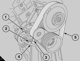
4 Loosen the pivot bolt (A1), the adjustment link bolt
(A2) and the bolt which holds the adjustment link to
the front mounting (A3). Remove the drive belt(s)
(A4).
5 Hold the alternator, remove the adjustment link and
the pivot bolt and lift away the alternator from the
engine.
To fit
1 Hold the adjus tment link for the alternator belt
against the front face of the front mounting of the
engine. Retain it loosely with its bolt, its nut and its
spring washer.
2 Hold the alternator between the support bracket
and the assembly of the tensioner pulley. Insert
loosely the pivot bolt, with a spring washer under its
head, through the bracket and the alternator and into
the threaded hole in the backplate of the pulley
assembly. Fit the bolt for the adjustment, with a plain
washer under its head, through the slot in the
adjustment link and through the lug of the alternator.
Fit loosely a plain washer, a spring washer and a nut
to the bolt.
3 Fit the drive belt(s) of the alternator around the
pulleys of the crankshaft and the alternator. Move the
alternator on the pivot bolt to tighten the belt(s). Refer
to section 4 of the User’s Handbook TSD 3138 for
details of how to adjust the tension of the alternator
belts. When the tension is correct, tighten securely
the two nuts on the bolts of the adjustment link and,
also, the pivot bolt of the alternator.
4 Connect the cables at the alternator.
5 For engines which are remotely cooled, fit the
alternator guard.
6 Connect the battery.
To dismantle and to assemble
拆卸和组装
To assemble
组装
1 Fit the spacer (A10) on the rotor shaft, with the large
1安装垫片(A10)在转子轴上,与大
diameter next to the rotor. Press the housing of the
转子的直径。按住房的
drive end and its bearing on to the rotor shaft. Apply
驱动端及其轴承在转子轴上。应用
pressure only to the inner race.
压力只有内在的比赛。
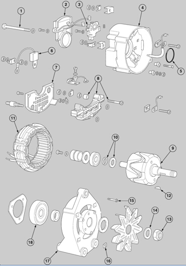
Before the alternator is dismantled, mark all housings
在交流发电机被拆除之前,所有的外壳都有
to ensure that their correct relationship is obtained
确保他们的正确关系得到
during assembly. For these operations, refer to the
在装配过程中。对于这些操作,指
illustration (A) on page 219.
插图(219页)。
1 Release the nut (A13) of the fan, remove the
1松开螺母(A13)的风扇,拆下
washer, the fan (A14) and the pulley. Remove the
洗衣机,风扇(14)和滑轮。拆下
’Woodruff’ key (A12) from the shaft and withdraw the
“半圆键(A12)从轴上取
spacer.
间隔。
2 Remove the suppression capacitor (A6) from the
2去除抑制电容器(A6)从
main output terminals, release the three screws and
主要输出端子,松开三个螺钉并
lift away the end cover (A7).
解除了端盖(A7)。
3 Remove the two screws and the ’Belleville’ washers
3取下两个螺钉和垫圈的碟形的
which retain the regulator (A2), and disconnect the
保持器(A2),并断开
’Luc ar’ terminals - two on the holder of the carbon
卢克AR的终端-两对碳架
brushes (A3) and one on the negative rectifier (A8).
刷子(A3)和一个负整流(A8)。
4 Disconnect the remaining ’Lucar’ terminal from the
4断开其余的卢卡的终端从
holder of the carbon brushes and lift away the
碳刷的持有人,并解除了
assembly of the holder.
持有人大会。
5 Remove the four sc rews (A15) and the square nuts
5删除四、螺丝钉(A15)和方形螺母
(A16) which are inserted in the housing of the drive
(A16),插入驱动住房
end.
结束。
6 Remove the long bolts (A1) and separate the
6去除长螺栓(A1)和分离
assembly of the rotor and the housing of the drive end
转子和驱动端的壳体的装配
from the assembly of the stator and the housing of the
从装配的定子和外壳的
slip ring end.
滑动环端。
7 Remove the three screws from the plate which
7从板中取出三颗螺丝
retains the bearing in the housing of the drive end
保留轴承在外壳的驱动端
(A17). Press out, or use a puller to remove, the
(A17)。压出,或用拉具拆卸,该
assembly of the rotor (A9) and the bearing (A18).
转子的装配(A9)和轴承(A18)。
8 Unsolder the three wires of the stator (A11) from the
8如果三线的定子(A11)从
assembly of the rectifier. Separate the stator from the
整流器组件。从定子中分离
housing of the slip ring end (A4).
滑环的端盖(A4)。
2 Fit a new ’O’ ring (A5) to the hous ing at the slip ring
2安装新的O型圈(A5)在滑环的住宅
end.
结束。
3 Inspect the insulation sleeves and renew them if
3检查绝缘套管,并将其更新
necessary. Fit the assembly of the stator to the
必要的。将定子装配到
housing of the slip ring end. Ensure that the bolt
滑动环端壳体。确保螺栓
holes, and the marks which indicate the correct
孔,并指出正确的标志
relationship of the housings, are aligned correctly.
外壳的关系,正确对齐。
4 Fit carefully the assembly of the rotor and the
4小心装配转子和转子
housing of the drive end into the assembly of the
驱动端的外壳进入装配的
stator and the housing of the slip ring end. Ensure
定子和壳体的滑动环结束。确保
that the bolt holes, and the marks which indicate the
螺栓孔,并标明了
correct relationship of the housings, are aligned
正确的关系的外壳,对齐
correctly.
正确。
5 Before the four long bolts are fitted, put a ’Belleville’
5前四个长螺栓安装,把一个“碟”
washer under each head. Tighten evenly the bolts to
每个头下的洗衣机。将螺栓均匀拧紧
the correct torque of 4.9 Nm (44.0 lbf in).
4.9 nm的正确的扭矩(44磅)。
6 Fit the assembly of the holder for the carbon
6安装碳源的支架
brushes, fit the screws and the ’Belleville’ washers
刷,安装螺丝和“碟形的垫圈
and tighten to 1.69 Nm (15.0 lbf in). Ensure that the
拧紧到1.69 nm(15磅)。确保
carbon brushes move freely in their holders.
碳刷自由移动在其持有人。
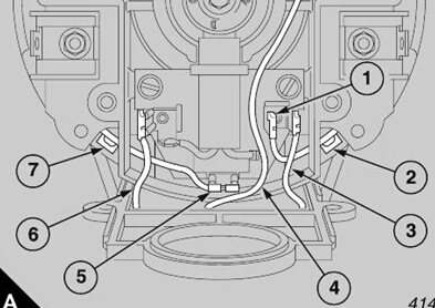
7 Connect the D+ and the F- cables to the Lucar
7将D和F -电缆卢卡
terminals as shown (A). Ensure that both of the
如图所示(一)。确保两者的
cables are retained under the internal lugs in the
电缆被保留在内部耳
casting.
铸造。
8 Use two screws and the ’Belleville’ washers to fit the
8用两个螺钉和垫圈的碟形的配合
regulator after the connections are made. Tighten
连接后的调节器。拧紧
evenly the screws to 1.69 Nm (15.0 lbf in).
均匀的螺丝1.69 nm(15磅)。
9 Bend the negative tags of the diodes down toward
9把二极管的负标记向下弯曲
the heat sink. Bend down each wire of the stator and
散热片。每根导线的弯曲
solder it to its tag, together with the wire of the
把它焊在标签上,连同电线
auxiliary diode. Solder the bottom face of each
辅助二极管。焊底面
positive tag, bend the tags around the wires of the
积极的标签,弯曲的电线上的标签
stator and solder the connections.
定子和焊连接。
10 Fit the end cover and tighten the three screws to
10安装端盖并拧紧三个螺钉
1.69 Nm (15.0 lbf in).
1.69 nm(15磅)。
11 Fit the suppression capacitor.
11配合的抑制电容。
To clean
清洁
1 All components should be cleaned thoroughly
1所有部件应彻底清洗干净
before they are inspected.
在他们被检查之前。
2 Remove all dirt and carbon from the components by
2去除所有的污垢和碳的组成部分
the careful use of compressed air and clean the stator
小心使用压缩空气和清洁定子
by the use of a cloth which is damp with white spirits.
用一种潮湿的布,白色的精灵。
To ins pect and to correct the rotor 23-4
INS PECT和纠正转子测量
1 Check the threads, the keyway s and the bearing
1检查螺纹、键槽、轴承
surfaces for damage.
损坏的表面。
2 Use a 110 volt 15 watt test lamp to test the
2使用一个110伏15瓦的测试灯来测试
insulation between the slip rings and the windings of
之间的滑动环和绕组的绝缘
the rotor, and the body of the rotor.
转子和转子的身体。
3 Use an ohmmeter to check the resistance of the
3用欧姆表检查的阻力
windings of the rotor. The resistance should be 14
转子绕组。电阻应为14
ohms ± 0.2 ohm at an ambient temperature of 20°C
±欧姆0.2欧姆在20°C环境温度
(68°F).
(68°)。
4 Check that the slip rings are concentric and are not
4检查滑环是否同心,不
worn or damaged. If necessary, check the tightness
磨损或损坏。如有必要,检查密封性
of the screw which retains the slip rings and use a
的螺丝,保留的滑动环和使用
lathe to remove only the minimum material from the
车床,以除去的最小材料从
rings. The minimum diameter is 24.69 mm (0.972 in).
环。最小直径为24.69毫米(0.972英寸)。
If the slip rings are badly worn or damaged they
如果滑环磨损严重或损坏
should be renewed as follows:
应更新如下:
5 Unsolder carefully the wires of the windings from
5如果仔细的绕组线
the pegs of the slip rings.
该滑环销钉。
6 Remov e the screw which retains the slip rings.
6移除螺丝保留滑环。
7 Withdraw the assembly of the slip rings from the
7撤回从中的滑动环的装配
shaft.
轴。
8 Align the wires from the windings of the rotor with
8将导线从转子的绕组中对齐
the slots in the assembly of the new slip rings.
新的滑环装配中的槽。
9 Press the assembly of the new slip rings onto the
9将新的滑动环装配到
shaft.
轴。
10 Fit the screw and the washer to retain the s lip
10安装螺丝和垫圈以保持嘴唇
rings. Tighten the screw to 2.3 Nm (20 lbf in).
环。拧紧螺钉2.3 nm(20磅)。
11 Wrap each wire from the windings of the rotor
11每根导线从转子绕组
approximately three turns around the relevant peg of
约三转的相关的挂钩
the slip rings and solder the connections.
滑动环和焊料连接。
12 Remove the surplus lengths of the pegs and
12拆下钉的剩余长度
remove all excessive solder so that the shape of the
除去所有过量的焊料,使其形状
pins and the wire can be seen.
引脚和电线可以看到。
To remove and to fit the rectifier
To test the main diodes with an ohmmeter or
1 Unsolder the D+ wire from the terminal of the
auxiliary diodes.
Caution: Do not try to turn the round section of the
negative terminal because it is retained by splines in
the negative rectifier.
2 Release the small nut, and remove the two spring
washers and the insulation bush from the inner side of
the housing.
3 From the outside of the housing, release the small
nut, and remove the ’Belleville’ washer and the ’Lucar’
terminal from the negative rectifier.
4 Remove the rectifier and ensure that the two
insulation washers are not lost, remove the square
headed bolt and the other insulation bush.
1 Insert an insulation bush and the square headed
bolt in the inner side of the housing. Fit the insulation
washer to the bolt on the outside of the housing.
2 Fit the insulation washer to the negative terminal on
the rectifier and insert the rectifier into the housing.
3 Fit the ’Lucar’ terminal, the ’Belleville’ washer and
the nut to the square headed bolt to retain the rectifier.
4 Fit correctly the insulation bush onto the negative
terminal on the inner side of the housing, fit the two
spring washers and the nut and tighten to 3.11 Nm
(26.5 lbf in).
5 Tighten the nuts which retain the rectifier to 2.0 Nm
(17 lbf in). Ensure that the ’Lucar’ terminal has
suitable clearance from the terminal of the auxiliary
diodes when the wires are fitted.
6 Solder the D+ lead onto the terminal of the auxiliary
Single diodes cannot be renewed. If a diode is found
to be faulty, the complete rectifier assembly must be
renewed. The diodes can be tested easily by the use
of an ohmmeter or by a 12 or 24 volt DC electrical
supply and a test lamp of low watts.
By the use of an ohmmeter
1 Connect one probe to the body of the rectifier and
the other probe to the connections of the three diodes
in sequence and check the resistances.
2 Check again with transposed probes to obtain a
reverse current.
3 These checks should show a low resistance in one
direction, and a very high resistance in the other
direction.
4 A low resistance in both directions indicates an
unserviceable diode.
5 A high resistance in both directions indicates that
there is no continuity in the circuit of the rectifier.
By the use of a test lamp
1 The test lamp should illuminate only in one
direction.
2 If the lamp illuminates in both directions, the diode
is unserv iceable.
3 If the lamp does not illuminate in either direction,
there is no continuity in the circuit of the rectifier.
To test the auxiliary diodes
23-7
To check and to renew the
carbon brushes
23-9
|
equipment and method as for the main diodes,
operation 23-6.
1 Put one probe on the terminal (at the point where
the D+ cable is soldered), and the other probe on
each of the three connections of the main diodes in
sequence. Transpose the probes to finish the check.
D+ and F- wires Caution: Do not try to turn the screws at the inner
side of the housing.
1 Remove the nut, the ’Belleville’ washer, the ’Lucar’
terminal and the guard of the terminal from the
outside of the housing. Remove the screws, the
terminal, and the insulator of the terminal from the
inner side of the housing.
2 Check the continuity and insulation of the D+ and
F- wires.
3 At the inner side of the housing fit the insulator for
the terminal. Ensure that the extension is toward the
bearing. Fit the terminal of the wire with the
connections toward the bearing and the openings
upward. Insert, correctly and fully, the square headed
section of the screw into the insulator.
4 From the outside of the housing, fit the guard of the
terminal, the ’Lucar’ terminal, the ’Belleville’ washer
and the nut. Tighten the nut to 3.11 Nm (26.5 lbf in).
|
1 Check the holder of the carbon brushes for signs of
damage and especially for cracks.
2 Chec k the carbon brushes for damage and ensure
that they are suitable for use. The minimum possible
protrusion of the carbon brushes from the holder must
be 10.0 mm (0.394 in).
To renew
1 Unsolder the wires of the carbon brushes from the
terminals and withdraw the carbon brushes from the
holder. Keep the insulation sleeves if they are
suitable for further use.
2 Fit the sleeves to the wires of the new carbon
brushes and insert them through the centre of the
spring and through the s mall hole.
3 Pull the wire of the carbon brush until the maximum
projection of the carbon brush is 15.0 mm (0.590 in).
Wrap the wire one complete turn around the terminal
and solder the connection. Remove all s urplus wire.
the housing 23-10
1 Check the windings of the stator for burned or
broken wires, and for damage to the insulation.
2 Use a 110 volt 15 watt test lamp to test the
insulation between the body of the stator and each of
the three wires in turn.
3 Check the resistance between two wires and check
all of the wires in sequence. Resistance across two
phases should be 0.485 ohms.
To inspect the bearings
The bearings are sealed for life and do not need a
service.
Caution: Original bearings should be checked for
wear or roughness when they are operated. The
bearing at the drive end has integral seals which
should be checked for damage or distortion. If the
condition of the original bearings is in doubt, new
bearings should be fitted.
|
|
23-4 paragraphs 5 to 7.
2 Remove the deflector type washer.
3 Press, or use a puller to remove, the bearing from
the rotor s haft. Remove the spacer and the thin
washer.
4 Check the wires and return them to the grooves. Fit
the thin washer and the spacer.
5 Press the new bearing onto the shaft. Apply
pressure only to the inner race.
6 Fit the deflector type washer and fit the assembly of
the slip rings on the rotor shaft, operation 23-4
paragraphs 8 to 12.
drive end
or use a puller to remove, the bearing from
the rotor shaft. Ensure that the spacer is not lost and
make a note that the tapered side is toward the
bearing.
2 Press the new bearing into the housing of the drive
end. Apply pressure only to the outer race.
3 Fit the plate which retains the bearing. Use ’Loctite
242’ on the threads of the screws and tighten the
three screws to 1.69 Nm (15.0 lbf in).
400-100-8969 15088860848
0574-26871589 15267810868
0574-26886646 15706865167
0574-26871569 18658287286
