 English
 Espaol
 Franais
 阿拉伯
阿拉伯 中文(简)
中文(简) Deutsch
 Italiano
 Português
 日本
日本 韩国
韩国 български
 hrvatski
 esky
esky Dansk
Dansk Nederlands
 suomi
suomi Ελληνικ
 印度
印度 norsk
norsk Polski
 Roman
Roman русский
 Svenska
英国帕金斯柴油发电机组启动马达维修技术资料
英国帕金斯柴油发电机组启动马达维修技术资料

Starter motor
起动马达
To remove and to fit
要删除和以适应
It is not advisable to attempt repairs to the starter
试图修理初学者是不明智的
motor. This work requires specialist equipment and
电机。这项工作需要专门的设备和
knowledge. If starter motor failure occurs, operator’s
知识。如果发生起动电机故障,操作员的
are advised to take advantage of the Perkins service
建议利用帕金斯服务的优势
exchange scheme.
交换方案。
To remove
删除
1 Disconnect the battery.
1断开蓄电池。
2 Make a note of the terminals of the starter motor
2作起动电机端子的说明
assembly and of the cables which are connected to
组装和连接到的电缆
them.
他们。
3 Disconnect the cables from the starter motor
3断开电机的电缆
assembly.
装配。
4 Remove the three bolts and the spring washers and
4拆下三个螺栓和弹簧垫圈
withdraw, carefully, the assembly of the starter motor.
起动电机的装配,退出,小心。
To fit
适合
1 Fit carefully the assembly of the starter motor to the
1小心地将起动电机的总成
flywheel housing and fit the three bolts and the spring
飞轮壳和配合的三个螺栓和弹簧
washers to retain it.
保留的垫圈。
2 Connect the c ables to the correct terminals.
2将C项为正确的终端。
3 Connect the battery.
3连接电池。
To dismantle
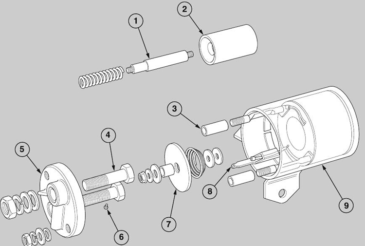
4 Hold the protrusion of the plunger (A2) at the
opposite end of the body (A9) and release the nut
which retains the switch assembly on the shaft (A1).
Remove the washer, the insulation bush, the
contactor disc (A7), the spring, the second insulation
washer and the second washer from the shaft and
withdraw the plunger and the spring from the opposite
1 Remove both jumper leads from between the
solenoid s witch and the starter body.
A special tool will be needed for the next part of the
operation. The tool can be manufactured from a ¼
inch AF socket; the outside diameter of the socket
must be ground down to 9 mm (0.345 in).
2 Extract the rubber plug from the solenoid base,
insert the special tool, engage it with the timing shaft
and turn it anti-c lockwise until the plunger and arm are
released from the shaft. Unscrew the two retaining
bolts and remove the solenoid switch.
3 Remove the lock nuts, the washers and the sealing
rings from both of the small terminals; partially
withdraw the end cover (A5) and release the small
sc rew (A6) from the head of the terminal (A8) which
retains the connection of the winding. Remove the
end cover (A5) complete with the large terminals (A4),
the lock nuts, the washers and the sealing washers.
Remove also the terminal insulators (A3).
1 Assemble the shaft (A1) and the plunger (A2), if
they have been separated, and fit the spring to the
shaft.
2 Fit the shaft through the body (A9) of the solenoid
switch and fit the washer, the insulation washer, the
spring, the contactor disc (A7), the insulation bush,
the second insulation washer, the washer and the nut
in the correc t sequence as shown (A). Hold the
plunger and tighten the nut.
3 Fit the terminal insulators. Fit the cover to the body
just enough for the small screw (A6) to be fitted
through the connection and into the side of terminal 3.
Fit completely the cover and fit the washers, the
sealing rings and the lock nuts.
4 Fit a new rubber shroud (page 228/A15) to the
housing of the shift lever and ensure that the lip is
engaged fully in the groove.
5 Align the screw link with the threaded hole in the
solenoid plunger (A2) and insert the special tool
through the hole at the centre of the housing. Turn
clockwise the plunger until it reaches the end of the
thread and insert the solenoid switc h in the housing
for the shift lever.
6 Fit the two bolts which fasten the solenoid switch to
the starter motor and tighten them to 34,0 to 39,5 Nm
(300 to 350 lbf in). Turn the plunger anti-clockwise by
approximately five turns.
7 DO NOT fit the flexible cable and the copper
connector until the adjustment of the solenoid is
completed in operation 23-22.
|
To assemble
To dismantle
1 Remove the solenoid switc h, operation 23-15.
Before the starter motor is dismantled, mark the
edges of each section of the starter motor to ensure
their correct relationship during assembly.
2 Remove the carbon brush cover (A4), release the
connections and carefully withdraw the carbon
brushes (A3).
3 Disconnect the two cables from the field windings
(A7), release the four bolts and remove the end cover
(A1). Withdraw the armature (A5).
4 Release the six c ap screws and remove the pinion
housing (A8); dis connect and remove the pinion
assembly (A10).
5 Remove the screw and washer from the housing
(A8); withdraw the pivot and remove the shift lever
(A12). Separate the housing from the yoke (A6).
Ensure that all the components are clean and dry
before they are assembled. Apply glycerine to the
new ’O’ rings and lubricate all the bushes with clean
SAE 5W/20 engine lubricating oil. Soak the fibre
washers and lubricator wicks in clean SAE 5W/20
engine lubricating oil.
1 Fit a new ’O’ ring around the end cover (A1) and
align the marks which indicate the correct relationship
with the yoke. Put new spring washers on the four
bolts which fasten the end cover to the yoke. Apply
’Loc tite AVV’ to the threads and fit the bolts. Tighten
each bolt to 12,5 to 17 Nm (110 to 150 lbf in).
2 Fit a steel thrust washer, followed by a fibre washer,
on to the armature shaft at the commutator end and
insert the shaft into the yoke assembly. Fit a steel
washer, followed by a fibre washer, onto the splined
end of the shaft and lubricate the shaft and the splines
with ’Aeroshell Grease No. DID 5598’.
3 Fit a new ’O’ ring around the housing (A14) and
apply some grease to the cams of the shift lever.
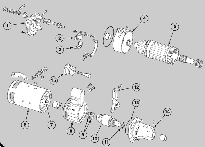
4 Put the housing (A8) over the protrusion of the shaft
and fit two fibre washers (A9) onto the shaft. Engage
the two cams of the shift lever in the groove of the
pinion assembly and slide the assembly and the
housing onto the shaft. Align the marks which
indicate the correct relationship of the housing and
the yoke, and apply ’Loctite AVV’ to the threads of the
five cap screws. Insert the cap screws, with new
spring washers, and tighten to 12,5 to 17 Nm (110 to
150 lbf in).
5 Fit the steel thrust washer (A11) onto the shaft and
against the pinion assembly. Fit a new ’O’ ring (A13)
to the pinion housing and put the housing around the
pinion. Align the marks which indicate the correct
relationship of the housings for the shift lever and the
pinion. Six new special cap screws, which have a
small square area of locking agent on the threads, are
inserted through the relevant holes of the housing for
the pinion and into the housing for the shift lever.
6 Tighten evenly the cap screws to 24,4 to 28,3 Nm
(216 to 250 lbf in).
7 Check that the armature turns freely, and fit the
carbon brushes into their holders (A2). Ensure that
the carbon brushes slide freely in the holders and
tighten the screws which retain the carbon brushes to
1,6 to 2,0 Nm (14 to 18 lbf in). Check that the wires of
the carbon brushes remain free.
8 Use a spring balance to check the springs of the
carbon brushes. Renew the s prings if the loads are
not within the limits of 1,42 to 1,68 kgf (50 to 59 ozf),
when the end of each spring is held in its correct
position in accordance with the length of a new
carbon brush.
9 Spread a thin application of glycerine on the gasket
of the cover (A4), and fit the ends of the cov er across
one of the ribbed sections of the yoke. Tighten the
two screws which retain the cover to 1,13 to 1,70 Nm
(10 to 15 lbf in).
10 Fit the solenoid switch, operation 23-15.

To clean
6 Inspect the bushes in the end cover of the
Use white spirits to clean all the components. Do
NOT dip the assembly of the pinion in the white
spirits, because the special lubricant in the assembly
will be eliminated.
To inspect and to correct
1 Use an ’Avometer’ to check the resistance of the
winding which pulls the plunger and the winding which
holds the plunger; these should be 1.34 and 2.7 ohms
respectively, at 20°C. Renew the solenoid switch if
the windings are defective.
2 Inspect the assembly of the yoke and the field
windings, and also the housings, of the starter motor
for damage. Use suitable equipment to check the
insulation of the field windings and to check that the
continuity is not broken. Renew the complete
assembly of the yoke and the field windings if any field
winding is defective.
3 Inspect the armature for wear and damage,
especially the splines. Check that there is no
deflection of the shaft. Renew the shaft if the run-out
exceeds 0,13 mm (0.005 in).
4 Use s uitable equipment to check that the continuity
and insulation of the armature windings are not
broken. The commutator should have a polis hed dark
copper finish. Check that the run-out of the
commutator is within 0,08 mm (0.003 in). If the
armature is generally acceptable, the surface of the
commutator may be corrected. Remove only the
minimum material from the face. The final diameter
must not be less than 52,375 mm (2.063 in).
5 Test the insulation of the holders for the carbon
brushes, and renew the carbon brushes if there is
damage or wear. The minimum permis sible length of
the carbon brushes is 15,9 mm (0.625 in).
commutator and in the pinion housing. If there are
indications of wear, use a 13/16 in BSF tapered tap as
a puller to withdraw the old bushes. Press in the new
bushes.
7 Use the measurements of the old bush to machine
a groove in the new bush which aligns with the
lubricator wick.
8 Put the end cover, or the housing for the pinion, in
a lathe and ream the new bush to obtain an internal
diameter of 19,100 to 19,152 mm (0.752 to 0.754 in).
Ensure that there is concentricity of the bore with the
location face of the shoulder.
9 Inspect the bush in the housing of the shift lever. If
necessary, renew the bush, and machine an oil
groove which is the same as the groove in the old
bush. Put the hous ing in a lathe and ensure that there
is concentricity of the bore with the location face of the
shoulder. Bore the new bush to obtain an internal
diameter of 22,200 to 22,250 mm (0.874 to 0.876 in).
10 Ins pect the shift lever and its shaft for wear and
damage, and check that the arrangement which
retains the shaft in the housing is usable.
11 Check that the contactor disc is not burnt and that
there is no erosion. If necessary, clean the contact
face with smooth emery paper, or machine only the
minimum material from the contact face (maximum
0,5 mm (0.002 in)). If the erosion exceeds this limit,
the contactor disc must be renewed.
12 Check the contact faces on the heads of the
terminals. Renew the terminals if they are burnt or if
there is erosion.
13 Inspec t the assembly of the pinion, and renew the
assembly if the components have excessive wear or
Caution:
Ensure that the 24 volt electrical supply is
connected to the correct terminals and that the
insulation on the connection wires is not damaged.
1 Connect a 24 volt power supply to the terminals 1
and 3 of the solenoid switc h to energise the solenoid.
Push carefully the assembly of the pinion against the
cams of the shift lever. Use the gauge GO 14001 (A)
to check that the gap between the face of the pinion
and the face of the thrust washer is 4,76 mm (0.187
in).
2 If an adjustment is necess ary, de-energise the
solenoid and use the special tool TO 69017 (A) to turn
the shaft of the plunger until the gauge just slides
between the face of the pinion and the face of the
thrust washer.
Caution: Adjustments must not be made while the
solenoid is energised. Do NOT energise the solenoid
for more than 30 seconds.
3 Fit the rubber plug in the hole in the centre of the
housing at the end of the solenoid switch; connect, at
the terminal (4), the flexible cable which is between
the solenoid and the starter motor and also fit the
copper connector.
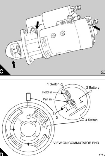
4 To test the solenoid switch for the correct operating
sequence, proceed as follows:
Fit a locally manufactured solid distance piece to the
pinion shaft to retain the drive and prevent the pinion
gear from moving. Connec t a 24 volt supply across
terminals 1 and 3, and check with an Avometer that
no reading is recorded between terminals 2 and 3 (D).
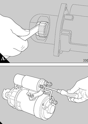
To fit the main starter cables
以配合主起动器电缆
23-20
对手
Caution: The main positive (red) s tarter cable is
注意:主要阳性(红色)的塔特电缆
fitted to the terminal on the solenoid switch and the
安装在电磁开关上的端子和
main negative (black) starter cable is fitted to the
主要负(黑色)起动器电缆安装
terminal on the end cover of the starter motor.
起动电机端盖端。
1 Fit the lugs of the relevant cables to the two
1符合有关电缆的两耳
terminals. Ensure that the polarity of the cables is
终端。确保电缆的极性
correct and fit the locking washers and the lock nuts,
正确、安装锁紧垫圈和锁紧螺母,
or the stiffnuts if relevant.
如果相关的或刚性螺母。
2 Hold a 19 mm (0.75 in) A/F spanner on the inner
2保持19毫米(0.75英寸)的A / F内扳手
lock nuts to ensure that they do not move while the
锁紧螺母,确保它们不动
outer nuts are tightened to 34 to 41 Nm (25 to 30 lbf
外螺母拧紧至34至41纳米(25至30磅
ft) with a suitable torque wrench.
英尺)用一个合适的扭矩扳手。
400-100-8969 15088860848
0574-26871589 15267810868
0574-26886646 15706865167
0574-26871569 18658287286
