 English
 Espaol
 Franais
 阿拉伯
阿拉伯 中文(简)
中文(简) Deutsch
 Italiano
 Português
 日本
日本 韩国
韩国 български
 hrvatski
 esky
esky Dansk
Dansk Nederlands
 suomi
suomi Ελληνικ
 印度
印度 norsk
norsk Polski
 Roman
Roman русский
 Svenska
发动机摇臂和摇臂轴的安装方法步骤与螺丝螺帽扭矩参数强鹿约翰迪尔John Deere
发动机摇臂和摇臂轴的安装方法步骤与螺丝螺帽扭矩参数强鹿约翰迪尔John Deere
1.将推杆安装在从中拆下的孔中。
2.在阀杆顶端安装耐磨盖,确保耐磨盖在阀杆上自由旋转。
3.将摇臂对准耐磨垫的中心。
4.将两个摇臂卡箍至气缸盖有头螺钉(A)拧紧至以下规格:
安装推杆和盖
初始摇臂
卡箍到缸盖盖
规格
螺钉扭矩…….30牛顿·米(22磅-英尺)
5.完全松开一个带帽螺钉。
6.将松动的带帽螺钉拧紧至以下规格:
最终摇臂
卡箍到缸盖盖
规格
螺钉扭矩转数……10 N•m+60 (7磅英尺+60)
7.对第二个带帽螺钉重复松开和扭转程序。如果摇臂未在耐磨垫上居中,松开两个带帽螺钉,然后重复该步骤。
8.调整强鹿约翰迪尔John Deere柴油发动机气门间隙。请参阅本组前面的调整气门间隙。
安装摇臂总成
检查并清洁呼吸机出口软管
1.检查摇臂盖上的通风机出口软管是否弯曲或损坏。必要时更换。
2.如果通风软管受限,请清洁通风软管。
完成强鹿约翰迪尔John Deere柴油发动机燃油泵侧的最终组装,
1.调整气门间隙(如果之前未进行)。
021 2.安装电子喷油器、燃油进口接头和燃油
40泄漏接头、燃油输送管和燃油泄漏管。请参阅CTM255第090组中的安装电子喷油器。
3.安装托架和摇臂盖。按照规范拧紧带帽螺钉。
规格
托架至缸盖盖
螺钉扭矩8牛顿·米(6磅-英尺)(72磅-英寸)
摇臂盖到托架盖
螺钉扭矩8牛顿·米(6磅-英尺)(72磅-英寸)
注意:确保通风机出口软管打开,适配器清洁。阻塞可能导致高油压和可能的机油损失。
4.将通风机出口软管连接到摇臂盖上的适配器,并牢固拧紧卡箍。
5.安装冷却液歧管。请参见第070组中的安装冷却液歧管。
完成强鹿约翰迪尔John Deere柴油发动机排气歧管侧的最终装配,
注:应用PT569 NEVER-SEEZ 复合或
等同于所有涡轮增压器带帽螺钉。
从未见过排气歧管带帽螺钉上不需要。导向螺柱可用于辅助装配。
1.使用新垫片安装进气歧管(B)。按照规范拧紧带帽螺钉。
规格
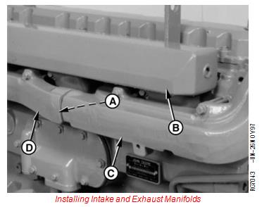
进气歧管至气缸压头扭矩……47牛顿·米(35磅-英尺)
安装进气和排气歧管
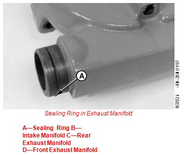
2.在后排气歧管(C)的凹槽中安装新的密封圈(a)。
3.安装前排气歧管(D)和后排气歧管。
4.使用新垫片和导向螺柱安装排气歧管总成。按照规范拧紧带帽螺钉。
规格
排气歧管至气缸
头部扭矩……47牛•米(35磅-英尺)
5.使用新的金属垫片安装涡轮增压器。应用PT569 NEVER-SEEZ 按照规范对带帽螺钉进行复合并拧紧。
规格
排气歧管中的密封圈
A-密封圈B-进气歧管C-后排气歧管
D-前排气歧管
涡轮增压器带帽螺钉-扭矩………24牛顿·米(18磅-英尺)
6.使用新垫片将涡轮增压器回油管连接到涡轮增压器。按照规范拧紧带帽螺钉。
规格
涡轮增压器回油管至涡轮增压器盖螺钉扭矩:27牛顿·米(20磅-英尺)
7.连接涡轮增压器进油口并拧紧。
8.如果强鹿约翰迪尔John Deere柴油发动机机油从曲轴箱中排出,则安装新的机油滤清器并加注正确等级和粘度的清洁机油。参见组002中的柴油强鹿约翰迪尔John Deere柴油发动机机油。
9.用清洁的冷却液加注冷却系统。请参见组002中的柴油强鹿约翰迪尔John Deere柴油发动机冷却液。
10.执行强鹿约翰迪尔John Deere柴油发动机磨合。请参阅本组后面的执行强鹿约翰迪尔John Deere柴油发动机磨合。
执行强鹿约翰迪尔John Deere柴油发动机磨合
1.在低怠速空载下运行强鹿约翰迪尔John Deere柴油发动机2分钟。检查有无液体泄漏。
2.将转速提高至快速怠速,然后将负载降至额定转速以上50 RPM,持续20分钟。
注:测功机是首选的负载控制,但可以通过将阻力负载与档位选择匹配来加载强鹿约翰迪尔John Deere柴油发动机。
3.重新检查气门间隙,必要时进行调整。参见本组前面的止回阀间隙序列号(200000-)。
4.安装摇臂盖垫片和盖。将摇臂盖带帽螺钉拧紧至技术规格。
规格
摇臂盖至气缸
有头螺钉扭矩…8牛顿·米(6磅-英尺)(72磅-英寸)不需要在强鹿约翰迪尔John Deere柴油发动机磨合后重新拧紧缸盖有头螺钉。
重要事项:强鹿约翰迪尔John Deere柴油发动机磨合后,请遵循以下步骤
操作员手册中列出的建议每小时服务间隔。
Install Rocker Arm Assembly Serial Number (200,000— )
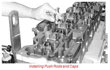
1. Install push rods in holes from which removed.
2. Install wear caps on valve stem tips, make certain caps rotate freely on valve stems.
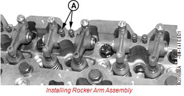
3. Align rocker arms centered on wear pads.
4. Tighten both rocker arm clamp-to-cylinder head capscrews (A) to specifications below:
Installing Push Rods and Caps
Initial Rocker Arm
Clamp-to-Cylinder Head Cap
Specification
Screw—Torque........ 30 N•m (22 lb-ft)
5. Loosen one cap screw completely.
6. Tighten loose cap screw to following specification:
Final Rocker Arm
Clamp-to-Cylinder Head Cap
Specification
Screw—Torque Turn ...... 10 N•m + 60 (7 lb-ft + 60)
7. Repeat loosening and torque turn procedure for second cap screw. If rocker arm is not centered on wear pads, loosen both cap screws, and repeat procedure.
8. Adjust engine valve clearance. See ADJUST VALVE CLEARANCE SERIAL NUMBER (200,000— ) earlier in this group.
Installing Rocker Arm Assembly
Inspect and Clean Ventilator Outlet Hose Serial Number (200,000— )
1. Check ventilator outlet hose on rocker arm cover for bent or damaged condition. Replace if necessary.
2. Clean ventilator hose if restricted.
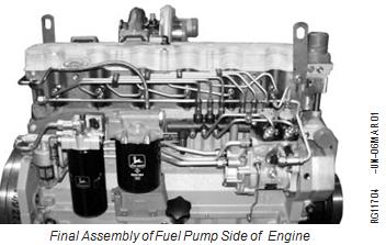
Complete Final Assembly of Fuel Pump Side of Engine Serial Number (200,000— )
1. Adjust valve clearance, if not previously done.
02
021 2. Install electronic injectors, fuel inlet connectors, fuel
40 leak-off connectors, fuel delivery lines, and fuel leak-off lines. See INSTALL ELECTRONIC INJECTORS, in Group 090 of CTM255.
3. Install carrier and rocker arm cover. Tighten cap screws to specifications.
Specification
Carrier-to-Cylinder Head Cap
Screws—Torque .................................................. 8 N•m (6 lb-ft) (72 lb-in.)
Rocker Arm Cover-to-Carrier Cap
Screws—Torque .................................................. 8 N•m (6 lb-ft) (72 lb-in.)
NOTE: Make sure ventilator outlet hose is open and adapter is clean. A restriction could cause high oil pressure and possible loss of oil.
4. Connect ventilator outlet hose to adapter on rocker arm cover and tighten clamp securely.
5. Install coolant manifold. See INSTALL COOLANT MANIFOLD in Group 070.
Complete Final Assembly on Exhaust Manifold Side of Engine Serial Number (200,000— )
NOTE: APPLY PT569 NEVER-SEEZ Compound or
equivalent to all turbocharger cap screws.
NEVER-SEEZ is not needed on exhaust manifold cap screws. Guide studs may be used to aid assembly.
1. Install intake manifold (B) using new gaskets. Tighten cap screws to specifications.
Specification
Intake Manifold-to-Cylinder
Head—Torque ....... 47 N•m (35 lb-ft)
Installing Intake and Exhaust Manifolds
2. Install a new sealing ring (A) in groove of rear exhaust manifold (C).
3. Assemble front exhaust manifold (D) and rear exhaust manifold.
4. Install exhaust manifold assembly using new gaskets and guide studs. Tighten cap screws to specifications.
Specification
Exhaust Manifold-to-Cylinder
Head—Torque ..... 47 N•m (35 lb-ft)
5. Install turbocharger using a new metal gasket. Apply PT569 NEVER-SEEZ Compound and tighten cap screws to specifications.
Specification
Sealing Ring in Exhaust Manifold
A—Sealing Ring B—Intake Manifold C—Rear Exhaust Manifold
D—Front Exhaust Manifold
Turbocharger Cap Screws—
Torque ......... 24 N•m (18 lb-ft)
6. Connect turbocharger oil return pipe to turbocharger using a new gasket. Tighten cap screws to specifications.
Specification
Turbocharger Oil Return Pipe-to-Turbocharger Cap
Screws—Torque .............................................................. 27 N•m (20 lb-ft)
7. Connect turbocharger oil inlet and tighten securely.
8. If engine oil was drained from crankcase, install new oil filter and fill with clean oil of correct grade and viscosity. See DIESEL ENGINE OIL in Group 002.
9. Fill cooling system with clean coolant. See DIESEL ENGINE COOLANT in Group 002.
10. Perform engine break-in. See PERFORM ENGINE BREAK-IN SERIAL NUMBER (200,000— ) later in this group.
Perform Engine Break-In Serial Number (200,000— )
1. Run engine at slow idle no load for 2 minutes. Check for liquid leaks.
2. Increase RPM to fast idle, then load down to 50 rpm above rated speed for 20 minutes.
NOTE: Dynamometer is the preferred load control, but engine can be loaded by matching drag loads to gear selection.
3. Recheck valve clearance and adjust as necessary. See CHECK VALVE CLEARANCE SERIAL NUMBER (200,000— ) earlier in this group.
4. Install rocker arm cover gasket and cover. Tighten rocker arm cover cap screws to specifications.
Specification
Rocker Arm Cover-to-Cylinder
Head Cap Screw—Torque.... 8 N•m (6 lb-ft) (72 lb-in.)
Retorque of cylinder head cap screws after engine break-in is not required.
IMPORTANT: After engine break-in, follow ALL
recommended hourly service intervals outlined in your Operator’s Manual.
约翰迪尔7830拖拉机——抢农时的有力保障,今年春季,部队某农副业基地克服种种不利的客观条件,抢前抓早,及时播种。该基地新引进的约翰迪尔7830拖拉机在今年的春播生产中大显神威,青海Perkins帕金斯4016-61TRG3强鹿约翰迪尔John Deere柴油发动机曲轴前后油封大概的价钱,甘南Perkins帕金斯4008TAG强鹿约翰迪尔John Deere柴油发动机柴油机油空气滤清器供应服务商,乌兰察布卡特caTC1.1强鹿约翰迪尔John Deere柴油发动机大修包一台多少钱,阿拉善Perkins帕金斯1106D-E70TAG3强鹿约翰迪尔John Deere柴油发动机气门导管油封去哪找,枣庄Perkins帕金斯403F-11强鹿约翰迪尔John Deere柴油发动机电子供油泵、提升输油泵电话,杭州Perkins帕金斯1506D-E88TAG5强鹿约翰迪尔John Deere柴油发动机汽缸床去哪找,三亚Perkins帕金斯4008TAG2强鹿约翰迪尔John Deere柴油发动机曲轴箱配件去哪找,牡丹江Perkins帕金斯403D-11强鹿约翰迪尔John Deere柴油发动机缸套组件多少钱,焦作Perkins帕金斯404D-22TAG强鹿约翰迪尔John Deere柴油发动机水温机油压力转速传感器代理商,充分展示了约翰迪尔拖拉机的优秀品质和给用户带来的真正价值。5月4日,该基地应用装配AutoTrac SF2 自动驾驶系统的约翰迪尔7830拖拉机进行试播,通过一下午的调试,驾驶员已经能够比较熟练的操作7830拖拉机进行播种作业。使用约翰迪尔拖拉机和Auto Trac SF2 自动驾驶系统大大提高了播种速度、减轻了驾驶员的疲劳强度,同时可以24小时不间断的播种,从而为抢农时提供了有力的保障。
400-100-8969 15088860848
0574-26871589 15267810868
0574-26886646 15706865167
0574-26871569 18658287286
