 English
 Espaol
 Franais
 阿拉伯
阿拉伯 中文(简)
中文(简) Deutsch
 Italiano
 Português
 日本
日本 韩国
韩国 български
 hrvatski
 esky
esky Dansk
Dansk Nederlands
 suomi
suomi Ελληνικ
 印度
印度 norsk
norsk Polski
 Roman
Roman русский
 Svenska
拆卸、检查和安装曲轴齿轮驱动辅助驱动装置约翰迪尔John Deere柴油机
拆卸、检查和安装曲轴齿轮驱动辅助驱动装置约翰迪尔John Deere柴油机
注:提供各种辅助驱动选项;所有选项的拆卸和安装类似。辅助驱动集成在约翰迪尔John Deere柴油机前正时齿轮盖中。有关辅助驱动附件的拆卸和辅助驱动部件的修理,请参阅CTM67-OEM约翰迪尔John Deere柴油机附件。
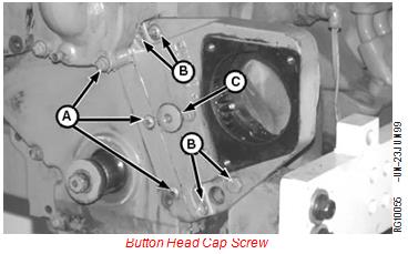
1.如有配备,拆下辅助驱动附件(空气压缩机、液压泵等)(显示为已拆下)。带帽螺钉
2.拆下约翰迪尔John Deere柴油机减震器(如图所示,已拆下)。
3.松开惰轮壳带帽螺钉(B)和正时齿轮盖带帽螺钉。
4.拆下按钮头带帽螺钉(C)。
5.使用D01209AA滑锤和附件从正时齿轮盖上拆下惰轮衬套/垫片(E)D) 并丢弃衬套/垫片。
辅助驱动惰轮衬套/垫片
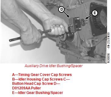
A-约翰迪尔John Deere柴油机正时齿轮盖带帽螺钉B-惰轮罩带帽螺钉C-按钮头带帽螺钉D-D01209AA拉具
E-惰轮衬套/垫片
6.拆下带帽螺钉(A-C),然后拆下惰轮壳和齿轮。
拆下惰轮壳至正时齿轮壳端面密封和O形圈。如果没有损坏,可以重复使用端面密封。
8.清洁并检查辅助传动总成是否有开裂的壳体、磨损或损坏的轴承以及损坏的齿轮或花键。根据需要更换部件。
A-约翰迪尔John Deere柴油机正时齿轮盖至气缸体带帽螺钉B-惰轮罩至正时齿轮罩带帽螺钉C-惰轮壳至气缸体有帽螺钉
9.润滑O形圈并将其安装在壳体孔(B)中。
注:内惰轮轴承支架有一个螺纹孔,安装在壳体的缸体侧。
10.如果已拆下,将惰轮安装到惰轮壳体内。安装带密封件的带帽螺钉(A),以将惰轮固定到位。
A-带帽螺钉B-壳体孔
11.将约翰迪尔John Deere柴油机惰轮轴插入惰轮壳体和惰轮,直到与壳体的缸体侧齐平。
重要事项:轴一端的白点必须面向约翰迪尔John Deere柴油机前部。
12.润滑惰轮壳后侧的O形环槽(A)。插入O形圈。O形环槽
注:如果端面密封未被切割、刻痕或损坏,则可重复使用。
13.使用短导向螺柱,将端面密封放置在正时齿轮盖开口上。密封件中的量规孔必须朝向开口底部。
重要事项:组装过程中,注意不要损坏端面密封或使惰轮壳背面的O形圈移位。
14.小心地将惰轮插入正时齿轮的开口中盖上惰轮,直到惰轮与曲轴齿轮啮合,按钮头带帽螺钉并且壳体抵靠面密封座。推动惰轮A按钮头带帽螺钉将衬套/垫片(D)插入块中。B型大O型圈C形小O形圈
15.检查大D形惰轮衬套/垫片上O形圈(B)和(C)的状况

按钮头带帽螺钉(A)。润滑O形圈并通过惰轮轴安装带帽螺钉。将其拧入块中,直到手指拧紧。
注意:中心正时齿轮盖到气缸体带帽螺钉必须有密封。
16.拆下导向螺柱。安装正时齿轮盖带帽螺钉(E)、惰轮罩带帽螺钉和带帽螺钉,用手拧紧。
17.按照以下顺序将带帽螺钉拧紧至规范:
•约翰迪尔John Deere柴油机惰轮壳至正时齿轮盖(A):
辅助驱动惰轮
规格
安装辅助驱动总成
壳体至正时齿轮盖(3/8英寸)-扭矩……41牛顿·米(30磅-英尺)
•惰轮壳至缸体(B)3/8英寸带帽螺钉:
规格
A-约翰迪尔John Deere柴油机惰轮壳至正时齿轮盖带帽螺钉
B-惰轮壳体至缸体带帽螺钉C-惰轮壳
D-约翰迪尔John Deere柴油机惰轮罩到缸体盖螺钉E-正时齿轮盖到缸体盖
螺钉
F-惰轮衬套按钮头带帽螺钉G-惰轮壳体至惰轮轴承带帽螺钉
辅助驱动惰轮
壳体至缸体(3/8英寸)-扭矩……41牛•米(30磅-英尺
•惰轮壳至缸体(D)1/2英寸带帽螺钉:
规格
辅助驱动惰轮
壳体到缸体(1/2英寸)-扭矩…127牛顿·米(94磅-英尺)
•惰轮衬套/垫片按钮头带帽螺钉(F):
规格
辅助驱动惰轮轴按钮
有头螺钉扭矩……150牛顿·米(110磅-英尺)
•正时齿轮盖至缸体(E):
规格
正时齿轮盖至气缸体带帽螺钉(5/16英寸)-扭矩……27牛顿·米(20磅-英尺)
•惰轮壳至惰轮轴承(G):
规格
辅助驱动惰轮
壳体至惰轮轴承(5/16英寸)-扭矩……27牛顿·米(20磅-英尺)
18.检查约翰迪尔John Deere柴油机惰轮到曲轴齿轮的齿隙。齿隙必须如下所示:
规格
辅助驱动惰轮
约翰迪尔John Deere柴油机齿轮到曲轴齿轮-齿隙……0.11-0.7 mm(0.004-0.028英寸)
19.安装减震器。

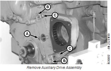
Remove, Inspect, and Install Crankshaft Gear-Driven Auxiliary Drive—If Equipped
NOTE: Various auxiliary drive options are available; removal and installation of all options are similar. The auxiliary drive is integrated into the engine front timing gear cover. Refer to CTM67-OEM Engine Accessories for removal of auxiliary drive accessories and repair of auxiliary drive components.
1. If equipped, remove auxiliary drive accessory (air
compressor, hydraulic pump, etc.) (shown removed). Button Head Cap Screw
2. Remove vibration damper (shown removed).
3. Loosen idler housing cap screws (B) and timing gear cover cap screws (A).
4. Remove button head cap screw (C).
5. Remove idler gear bushing/spacer (E) from timing gear cover using D01209AA Slide Hammer and Attachment
(D) and discard bushing/spacer.
Auxiliary Drive Idler Bushing/Spacer
A—Timing Gear Cover Cap Screws B—Idler Housing Cap Screws C—Button Head Cap Screw D—D01209AA Puller
E—Idler Gear Bushing/Spacer
6. Remove cap screws (A—C) and remove idler housing and gear.
Remove idler housing-to-timing gear housing face seal and O-ring. Face seal may be reused if not damaged.
8. Clean and inspect auxiliary drive assembly for cracked housing, worn or damaged bearings and damaged gear or spline. Replace components as required.
A—Timing Gear Cover-to-Cylinder Block Cap Screw B—Idler Housing-to-Timing Gear Cover Cap Screws C—Idler Housing-to-Cylinder Block Cap Screw
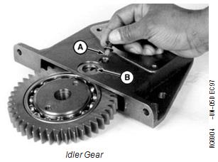
9. Grease and install O-ring in housing bore (B).
NOTE: Inner idler bearing support has one threaded hole, and is installed toward block side of housing.
10. If removed, install idler gear into idler housing. Install cap screw with seal (A) to hold idler gear in place.
A—Cap Screw B—Housing Bore
11. Insert idler shaft through idler housing and idler gear until flush with block side of housing.
IMPORTANT: White dot on one end of shaft must face out toward front of engine.
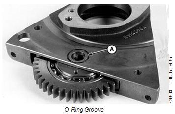
12. Grease O-ring groove (A) in back side of idler housing. Insert O-ring.
A—O-Ring Groove
NOTE: Face seal may be reused if it is not cut, nicked, or damaged.
13. Using a short guide stud, place face seal on timing gear cover opening. Gauge hole in seal must be positioned toward bottom of opening.
IMPORTANT: Be careful not to damage face seal or displace O-ring on back side of idler housing during assembly.
14. Carefully insert idler gear into opening of timing gear
cover until idler gear meshes with crankshaft gear, Button Head Cap Screw
and housing is seated against face seal. Push idler A—Button Head Cap Screw
bushing/spacer (D) into block. B—Large O-Ring
C—Small O-Ring
15. Check condition of O-rings (B) and (C) on large D—Idler Bushing/Spacer
button head cap screw (A). Grease O-rings and install cap screw through idler shaft. Thread into block until finger tight.
NOTE: Center timing gear cover-to-cylinder block cap screw must have a seal.
16. Remove guide stud. Install timing gear cover cap screws (E), idler housing cap screws (A and B) and cap screw (D) finger tight.
17. Tighten cap screws to specifications in the following sequence:
• Idler housing-to-timing gear cover (A):
Auxiliary Drive Idler
Specification
Install Auxiliary Drive Assembly
Housing-to-Timing Gear Cover
(3/8 in.)—Torque ...... 41 N•m (30 lb-ft)
• Idler housing-to-cylinder block (B) 3/8 inch cap screws:
Specification
A—Idler Housing-to-Timing Gear Cover Cap Screws
B—Idler Housing-to-Cylinder Block Cap Screw C—Idler Housing
D—Idler Housing-to-Cylinder Block Cap Screw E—Timing Gear Cover-to-Cylinder Block Cap
Screws
F—Idler Bushing Button Head Cap Screw G—Idler Housing-to-Idler Bearing Cap Screw
Auxiliary Drive Idler
Housing-to-Cylinder Block (3/8 in.)—Torque...... 41 N•m (30 lb-ft
• Idler housing-to-cylinder block (D) 1/2 inch cap screws:
Specification
Auxiliary Drive Idler
Housing-to-Cylinder Block (1/2 in.)—Torque.... 127 N•m (94 lb-ft)
• Idler bushing/spacer button head cap screw (F):
Specification
Auxiliary Drive Idler Shaft Button
Head Cap Screw—Torque ...... 150 N•m (110 lb-ft)
• Timing gear cover-to-cylinder block (E):
Specification
Timing Gear Cover-to-Cylinder Block Cap Screws (5/16 in.)—
Torque ..... 27 N•m (20 lb-ft)
• Idler housing-to-idler bearing (G):
Specification
Auxiliary Drive Idler
Housing-to-Idler Bearing (5/16 in.)—Torque...... 27 N•m (20 lb-ft)
18. Check idler gear-to-crankshaft gear backlash. Backlash must be as follows:
Specification
Auxiliary Drive Idler
Gear-to-Crankshaft Gear—
Backlash ...... 0.11—0.7 mm
(0.004—0.028 in.)
19. Install vibration damper.
柴油机的额定转速越高,就要求柴油的发火性好,以确保在短时问内燃烧完全,对柴油十六烷值的要求就高。一般情况下,额定转速在1 000r/min以下的柴油机,可使用十六烷值为35一40的柴油;转速在1 000~1 500r/min的柴油机,可使用十六烷值为40-45的柴油;转速在1 500r/min以上的柴油机,可使用十六烷值为45一60的柴油。
柴油的十六烷值对柴油机在不同气温下的启动性能也有影响,十六烷值高的柴油,即使在较低气温条件也易于启动。但柴油的蒸发性对约翰迪尔John Deere柴油机启动性的影响比十六烷值重要-,而十六烷值高的柴油,蒸发性就差些。葫芦岛Perkins帕金斯1106A-7-TAG2约翰迪尔John Deere柴油机柴油机油空气滤清器大概的价钱,中卫Perkins帕金斯2206A-E13TAG5约翰迪尔John Deere柴油机配件联系电话网站,克孜勒苏卡特柴油约翰迪尔John Deere柴油机G3512配件销售欢迎来电,哈密Perkins帕金斯1206E-E66TA约翰迪尔John Deere柴油机涡轮增压器供应服务商,澳门离岛帕金斯输油泵总成费用,烟台Perkins帕金斯404A-22G1约翰迪尔John Deere柴油机活塞肖卡簧一般多少钱,桂林CATC2.2柴油机哪里能买到费用报价单,娄底Perkins帕金斯1104C-44TAG1约翰迪尔John Deere柴油机机油泵供应服务商,潍坊Perkins帕金斯403F-15约翰迪尔John Deere柴油机启动马达网站,济南Perkins帕金斯4008TAG约翰迪尔John Deere柴油机高压油泵、油泵组件企业,兰州Perkins帕金斯403F-11约翰迪尔John Deere柴油机气门导管油封电话,十堰Perkins帕金斯1106D-E70TAG3约翰迪尔John Deere柴油机曲轴哪家好,所以,评定柴油的启动性应将十六烷值与柴油的蒸发性结合起来综合评定。
柴油的十六烷值高,其燃烧性能就好,但柴油的十六烷值过高了也不适宜。因为当柴油的十六烷值高于50后再继续提高,对着火延迟期的缩短作用不大。另外,十六烷值过肩的柴油其分子量均较大,使柴油的低温流动性、雾化与蒸发均受影响,会使燃烧不完全,导致约翰迪尔John Deere柴油机功率下降、油耗升高及排气冒黑烟。因此,在选用柴油时不应单纯地追求高十六烷值,通常要求柴油的十六烷恒在40一60之间,基本上已能满足高速柴油机的工作要求。GB252一87规定轻柴油的十六烷值应不小于45。
(4)提高柴油十六烷值的方法 提高柴油十六烷值的方法,一种是用硫酸或选择溶剂除去柴油中的芳香烃。这种方法柴油产率低、凝点提高且消耗大量硫酸或溶剂。另一种简便的方法是用石蜡基原油直按蒸馏制取柴油,这种直馏柴油其十六烷值可达50一60,甚至更高一些。但直馏柴油产量受限,故可在直馏柴油中调人 热裂化和催化裂化柴油馏分以增加产量。裂化柴油的十六烷值虽然只有30一40,但与直馏柴油调合后,可保证成品柴油的十六烷值达50左右。还有一种方法是通过向柴油中添加能提高十六烷值的添加剂,添加剂应无毒、能很好地溶解于柴油中、没有爆炸的危险、性能稳定、无腐蚀性且成本低。能满足上述要求的添加剂主要有丙***过氧化物、烷基******酯、四氢蔡过氧化物等。加入量一般根据添加剂的不同控制在0.*25%~3儿之间,可提高十六烷值16一24个单位,加注过量时,对提高十六烷值作用并不明显。这种方法的优点是:无成品损失也不改变柴油的凝点。采用添加剂的办法提高柴油的十六烷值必须考虑柴油本身的化学安定性。柴油本身的批学安定性好,添加剂加入后能在较长时间内发挥效用,否则,在柴油储存期问,其十六烷值就将降低。
400-100-8969 15088860848
0574-26871589 15267810868
0574-26886646 15706865167
0574-26871569 18658287286
